42 consider the circuit diagram depicted in the figure.
SOLVED:%o ) Problem 4: Consider the circuit diagram ... %o ) Problem 4: Consider the circuit diagram depicted in the figure. E1= 18V 0.5 Q 25 0 1,5 0 0.5 4 82 45V 50 % Part (a) What equation do yOu get when YOu apply the loop ule to the loop abcdefgha _ in terrns of the variables in the figure? Answered: Consider the circuit diagram depicted… | bartleby Transcribed Image Text. Consider the circuit diagram depicted in the fgure. It is known that two battery internal resistors r1and r2 are both 0.2Ω· = 12V and & = 24V. R2 16Ω 2. and Rs 262, but Ri is unknown. Caution: Current directions.
PDF E1.1 Circuit Analysis Problem Sheet 1 (Lectures 1 & 2) Ver 2427 E1.1 Analysis of Circuits (2014) E1.1 Circuit Analysis Problem Sheet 1 - Solutions 1. Circuit (a) is a parallel circuit: there are only two nodes and all four components are connected between them. Circuit (b) is a series circuit: each node is connected to exactly two components and the same current must ow through each. 2.
Consider the circuit diagram depicted in the figure.
MasteringPhysics: Problem Print View - hi Consider this diagram. Let us assume that it describes a series circuit containing a resistor, a capacitor, and an inductor. The current in the circuit has amplitude , as indicated in the figure. Which of the following choices gives the correct respective labels of the voltages across the resistor, the capacitor, and the inductor? PDF Chapter 28 Draw the circuit diagram and assign labels and symbols to all known and unknown quantities. Assign directions to the currents. The direction is arbitrary, but you must adhere to the assigned directions when applying Kirchhoff's rules Apply the junction rule to any junction in the circuit that provides new relationships among Consider the circuit diagram depicted in the figure Consider the circuit diagram depicted in the figure. What equation do you get when you apply the loop rule to the loop abcdefgha? If the current through the top branch is I_2 = 0.49 A. what is the current through the bottom, I_3, in amps?
Consider the circuit diagram depicted in the figure.. PDF Question 1 — Equivalent Circuits The Thevenin equivalent circuit is obtained after transforming the current source into a´ voltage source V(s) = Z(s)I(s) = RCv c(0) 1+sRC. This sequence of transformations is shown in Figure 3. Question 2 — Laplace domain circuit analysis Figure 4: RC circuit for Laplace analysis. Part (i) [3 marks] Consider the circuit depicted in Figure 4 ... Exercise 2 Consider the feedback system depicted in the ... It comprises of a resistor and capacitor connected in series to a voltage supply as shown below on Figure 1. Figure 1: RC Circuit If the capacitor is initially uncharged at zero voltage when the circuit is switched on, it starts to charge due to the current 'i' through the resistor until the voltage across it reaches the supply voltage SOLVED:% ) Problem 10: Consider the circuit diagram ... according to Joe, through some of the potential difference across the element in the circuit around any clothes. Forget movie view. That is the mission off. Lu… Consider the circuit diagram depicted in t... | Clutch Prep Problem: Consider the circuit diagram depicted in the figurePart (a) What equation do you get when you apply the loop rule to the loop abcdefgha?Part (b) If the current through the top branch is I2 = 0.49 A, what is the current through the bottom I3, in amps?
(10) Problem 1 Consider the circuit diagram depicted in ... View full document. (10%) Problem 1: Consider the circuit diagram depicted in the figure. <1.592 0.50 45 V A 50% Part (a) What equation do you get when you apply the loop rule to the loop abcdefgha, in terms of the variables in the figure? > A 50% Part (b) If the current through the top branch is 12 = 0.83 A, what is the current through the bottom, ... A capacitor of capacitance C is charged to ... - Toppr Ask Paragraph for Question no. 45 and 46 Consider a simple RC circuit as shown in figure 1. Process 1: In the circuit the switch S is closed att cut the switch S is closed at t - and the capacitor is fully charged to voltage (ie, charging continues for time T >> RC). A) Consider the combination of capacitors ... | Clutch Prep A) Consider the combination of capacitors shown in the diagram, where C 1 = 3.00 μF, C 2 = 11.0 μF, C 3 = 3.00 μF, and C 4 = 5.00 μF.. Find the equivalent capacitance C A of the network of capacitors. Express your answer in microfarads. B) Two capacitors of capacitance C 5 = 6.00 μF and C 6 = 3.00 μF are added to the network, as shown in the diagram. Find the equivalent capacitance C B ... 40 consider the circuit diagram depicted in the figure ... Consider the circuit diagram depicted in the figure Figure 12.2.2 (a) Time dependence of IR (t) and VR (t) across the resistor. (b) Phasor diagram for the resistive circuit. The behavior of IR (t)and can also be represented with a phasor diagram, as shown in Figure 12.2.2 (b).
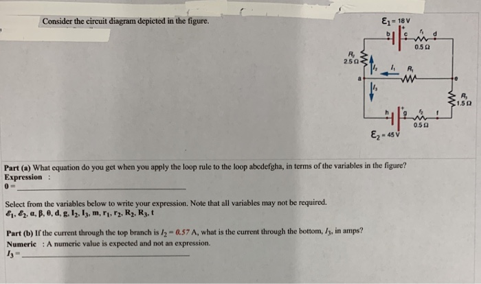
Consider a series RC circuit as in the figure below for ... Consider a series RC circuit as in the figure below for which R = 1.00 MΩ, C = 5.00 µF, and ε = 30.0 - YouTube. Consider a series RC circuit as in the figure below for which R = 1.00 MΩ, C = 5 ... Consider the circuit diagram depicted in the figure. a ... Consider the circuit diagram depicted in the figure. a. What equation do you get when you apply the loop rule to the abcdefgha, in terms of the variables in the figure? b. Consider the circuit shown in the figure. All the ... View solution. A circuit is shown in the figure. The ratio of current i2 i1 is. Medium. View solution. For the circuit shown in the figure. This question has multiple correct options. Hard. JEE Advanced. Consider the circuit diagram depicted in the figure. E- Ez ... Consider the circuit diagram depicted in the figure. E- Ez. as v Part(a) What equation do you get when you apply the loop rule to the loop abedefgha, in terms of the variables in the figure? Expression : Select from the variables below to write your expression. Note that all variables may not be...
Temperature measurement using a multi-wavelength fiber ring ...
Consider the circuit diagram depicted in the figure. E- Ez ... Consider the circuit diagram depicted in the figure. E- Ez. as v Part(a) What equation do you get when you apply the loop rule to the loop abedefgha, in terms of the variables in the figure? Expression : Select from the variables below to write your expression.

Logic Diagram - an overview | ScienceDirect Topics
Solved > Question Consider the circuit diagram depicted in ... Question : Question Consider the circuit diagram depicted in the figure. What equation : 646641. Consider the circuit diagram depicted in the figure. What equation do you get when you apply the loop rule to the loop abcdefgha, in terms of the variables in the figure? 0 = If the current through the top branch is I_2 = 0.69 A, what is the current ...
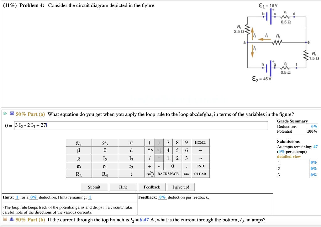
SOLVED:%) Problem 4: Consider the circuit diagram depicted in ...
Answered: ENL Consider the circuit diagram… | bartleby ASK AN EXPERT. ASK. Engineering Electrical Engineering Q&A Library ENL Consider the circuit diagram depicted in the figure. E- 18 V 0.50 250 ww 1.50 0.50 (a) What equation do you get when you apply the loop rule to the loop abedefgha, in terms of the variables in the figure? (b) If the current through the top branch is /037 A, what is the current ...

JLPEA | Free Full-Text | Inkjet Printed Fully-Passive Body ...
PDF EXAMPLE PROBLEMS AND SOLUTIONS - SUTech Simplify the block diagram shown in Figure 3-42. Solution. First, move the branch point of the path involving HI outside the loop involving H,, as shown in Figure 3-43(a). Then eliminating two loops results in Figure 3-43(b). Combining two blocks into one gives Figure 3-33(c). A-3-2. Simplify the block diagram shown in Figure 3-13.

Photon recycling in perovskite solar cells and its impact on ...
Consider the circuit shown in the figure below : All the ... Consider the circuit shown in the figure below : All the resistors are identical. The ratio I/I' is (A) 8 (B) 6 (C) 5 (D) 4 - Sarthaks eConnect | Largest Online Education Community. Consider the circuit shown in the figure below : All the resistors are identical. The ratio I/I' is (A) 8 (B) 6 (C) 5 (D) 4. ← Prev Question Next Question →.
Analysis on viewing angle of holographic image reconstructed ...
Consider the two circuits depicted in Figure 20.81. In ... Consider the two circuits depicted in Figure 20.81. In circuit 1, ohmic resistor R1 dissipates 5 watts; in circuit 2, ohmic. resistor R2 dissipates 20 watts. The wires and batteries have negligible resistance. The circuits contain 10-volt batteries. (a) What is the resistance of R1 and of R2?
Sensors | Free Full-Text | Quartz Crystal Microbalance ...
Solved Consider the circuit diagram depicted in the figure ... Solved Consider the circuit diagram depicted in the figure. | Chegg.com. Science. Physics. Physics questions and answers. Consider the circuit diagram depicted in the figure. What equation do you get when you apply the loop rule to the loop abcdefgha, in terms of the variables in the figure?
Negative-resistance models for parametrically flux-pumped ...
Solved Consider the circuit diagram depicted in the figure ... Physics. Physics questions and answers. Consider the circuit diagram depicted in the figure. What equation do you get when you apply the loop rule to the loop abcdefgha? If the current through the top branch is I_2 = 0.49 A. what is the current through the bottom, I_3, in amps?
Learn About Three-Op Amp Instrumentation Amplifiers ...
Consider the circuit diagram depicted in the figure Consider the circuit diagram depicted in the figure. What equation do you get when you apply the loop rule to the loop abcdefgha? If the current through the top branch is I_2 = 0.49 A. what is the current through the bottom, I_3, in amps?

Applying the Laplace Transform in LTspice to Model Transfer ...
PDF Chapter 28 Draw the circuit diagram and assign labels and symbols to all known and unknown quantities. Assign directions to the currents. The direction is arbitrary, but you must adhere to the assigned directions when applying Kirchhoff's rules Apply the junction rule to any junction in the circuit that provides new relationships among

Circuit diagram of the linear operator from the implemented ...
MasteringPhysics: Problem Print View - hi Consider this diagram. Let us assume that it describes a series circuit containing a resistor, a capacitor, and an inductor. The current in the circuit has amplitude , as indicated in the figure. Which of the following choices gives the correct respective labels of the voltages across the resistor, the capacitor, and the inductor?
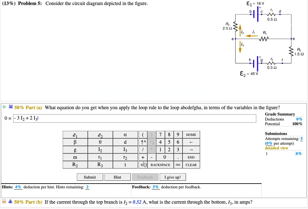
SOLVED:(13% ) Problem 5: Consider the circuit diagram ...
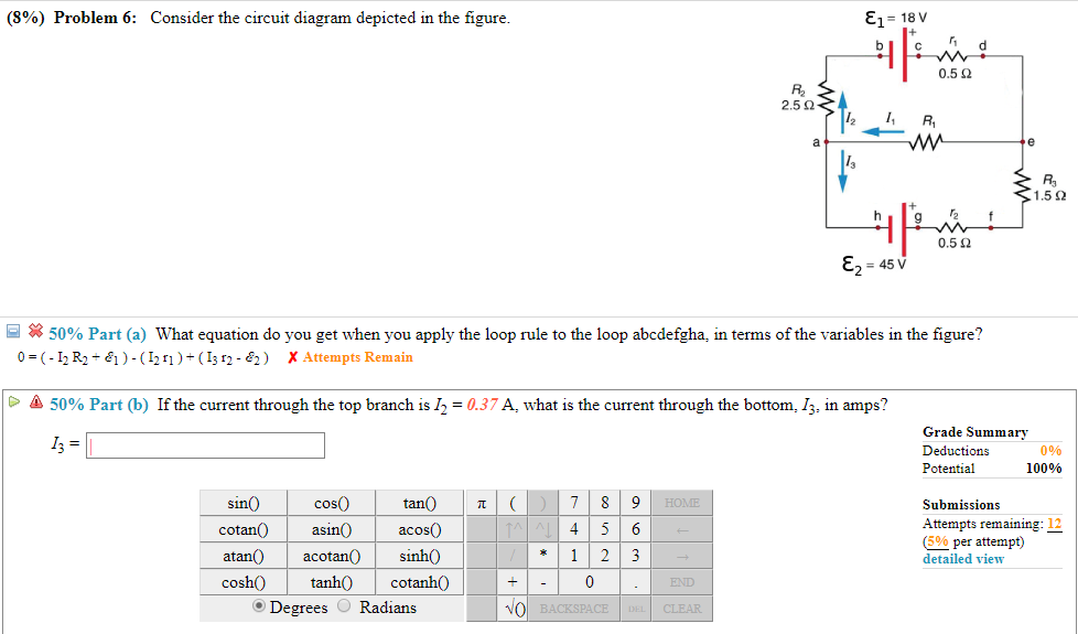
Solved (8%) Problem 6: Consider the circuit diagram depicted ...
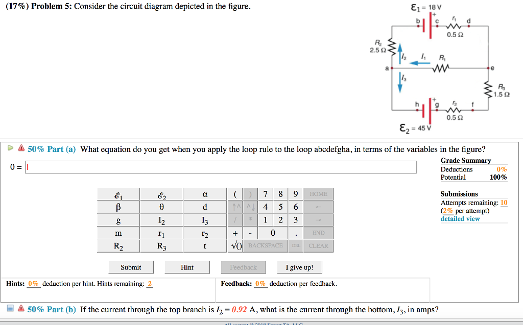
Solved (17%) Problem 5: Consider the circuit diagram | Chegg.com
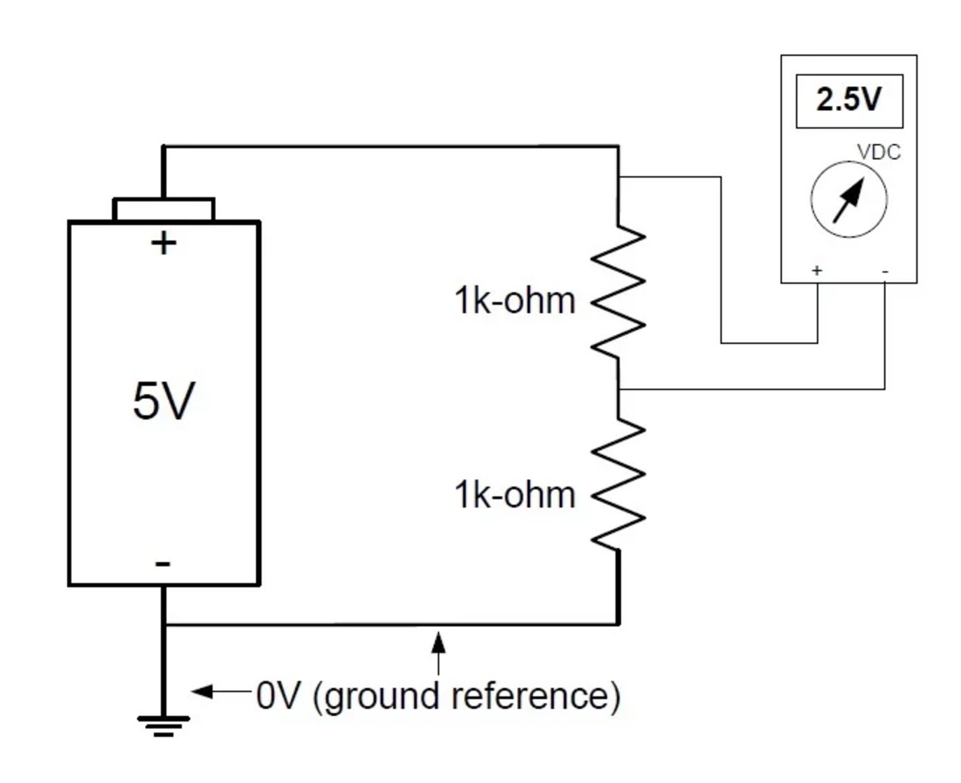
An Introduction to Ground: Earth Ground, Common Ground ...
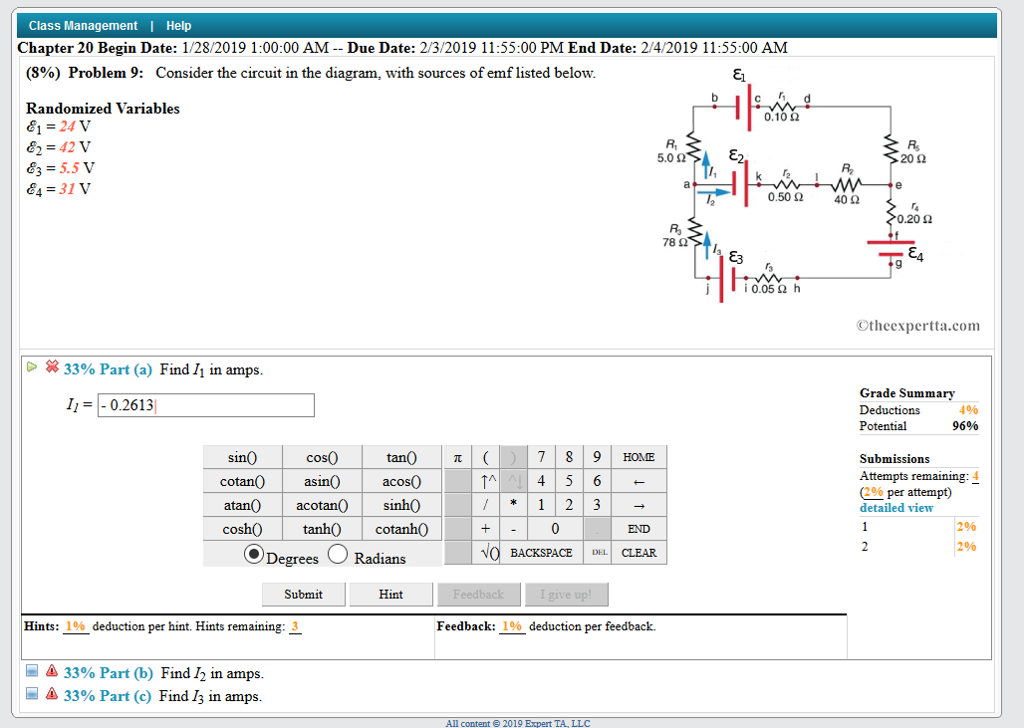
Solved Consider the circuit in the diagram, with the sources ...
Low Cost, Robust and Multi-Functional Smart Meter | IntechOpen
A Review of Emission Polarization
Sensors | Free Full-Text | Laser Self-Mixing Fiber Bragg ...
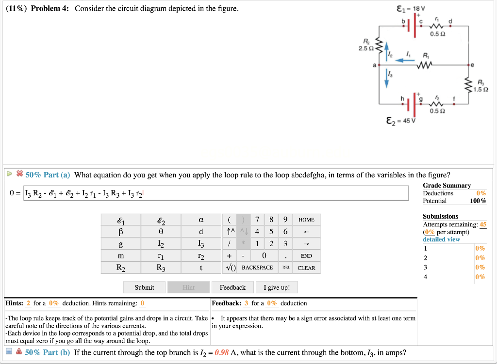
Solved (11%) Problem 4: Consider the circuit diagram | Chegg.com

Photon recycling in perovskite solar cells and its impact on ...

Logic Diagram - an overview | ScienceDirect Topics
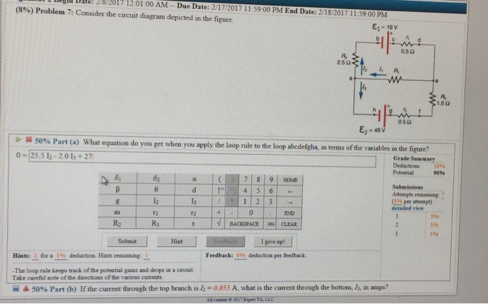
Solved L 2017 12:01:00 AM Due Date: 2/17/2017 11:59:00 PM ...

Basic Pneumatic Circuits - Tech Briefs
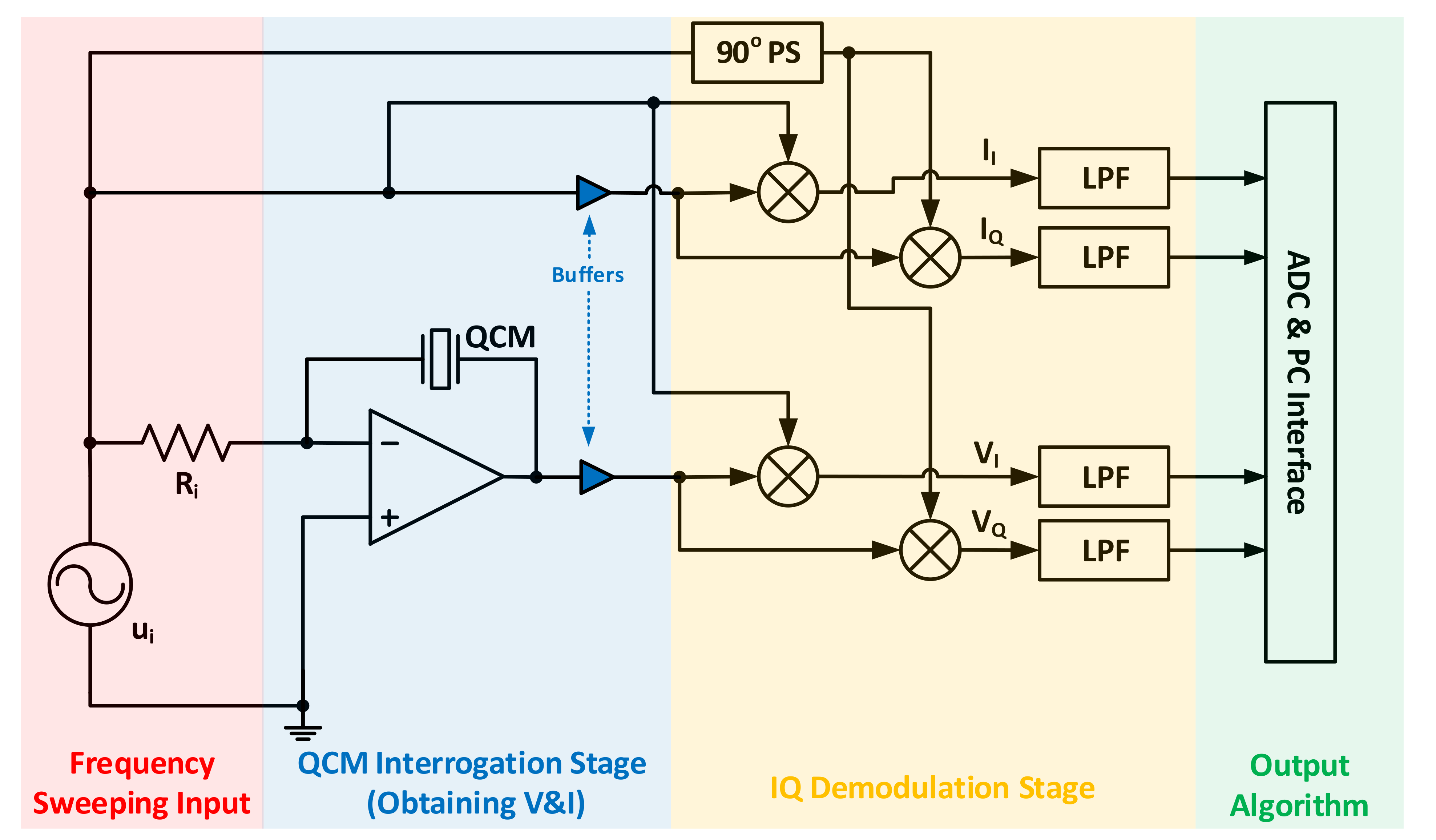
Sensors | Free Full-Text | Quartz Crystal Microbalance ...

Ideal Current Source - an overview | ScienceDirect Topics

10) Problem 1 Consider the circuit diagram depicted in the ...
IJMS | Free Full-Text | Relevance of a Novel Circuit-Level ...
Accelerating with FlyBrainLab the discovery of the functional ...
Local field enhancement using a photonic-plasmonic nanostructure
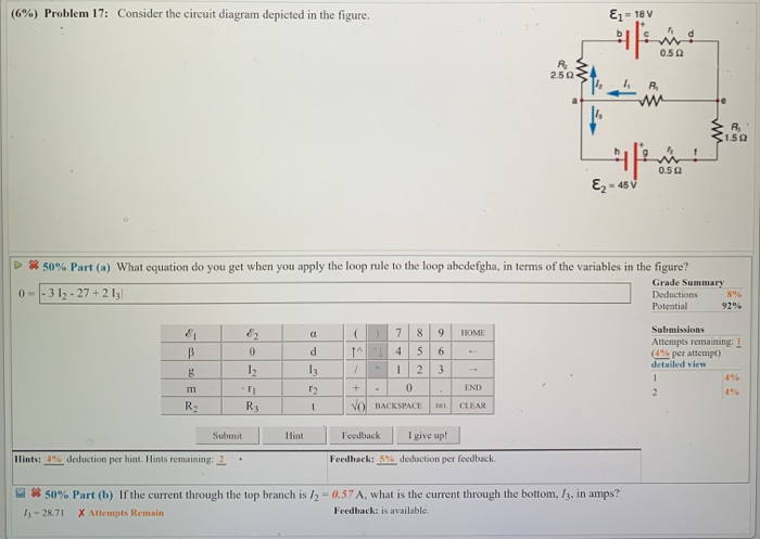
Solved (6%) Problem 17: Consider the circuit diagram | Chegg.com
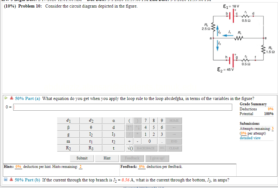
Solved (10%) Problem 10: Consider the circuit diagram | Chegg.com

Circuit diagram - Wikipedia
Comparison of femtosecond and nanosecond two-photon ...
Architecture agnostic algorithm for reconfigurable optical ...
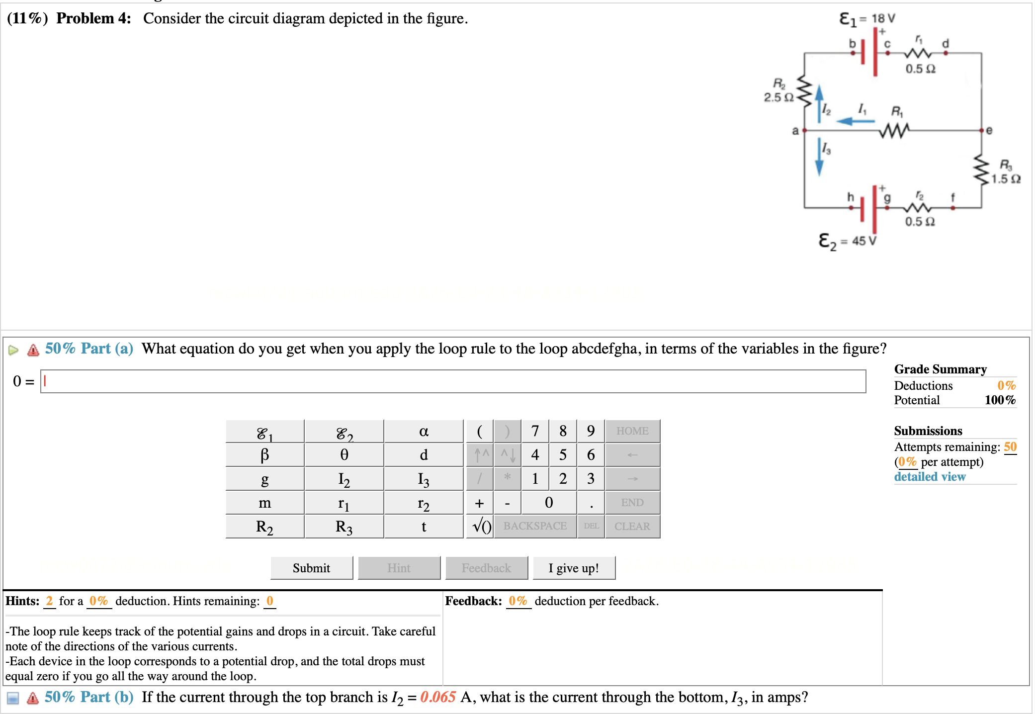
Solved (11%) Problem 4: Consider the circuit diagram | Chegg.com
Solved Consider the circuit diagram depicted in the figure ...
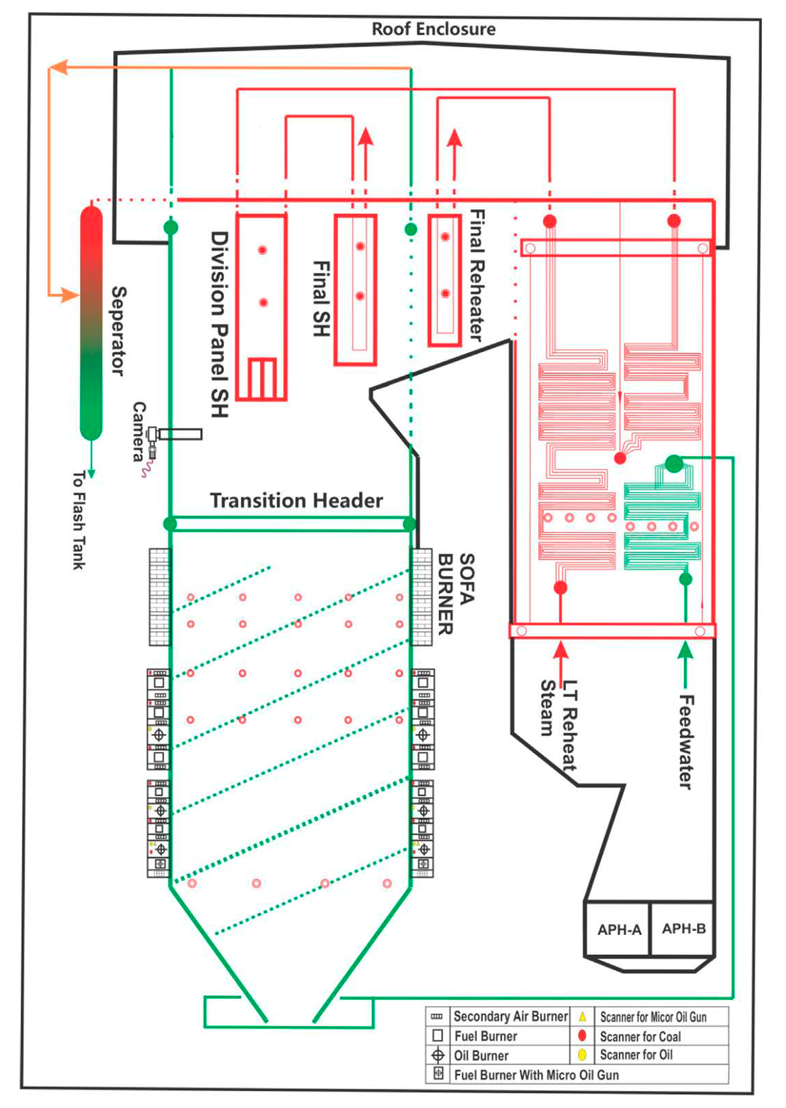
Energies | Free Full-Text | Optimization of a 660 MWe ...
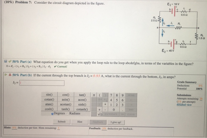
Solved (10%) Problem, 7: Consider the circuit diagram | Chegg.com

Using power MOSFETs in DC motor control applications | Nexperia
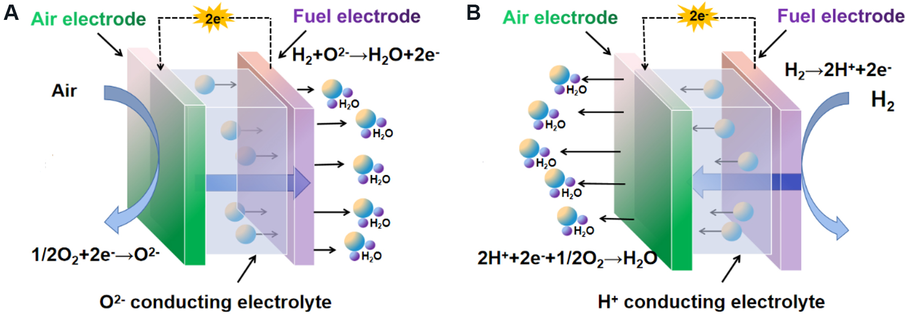
A nanoscale perspective on solid oxide and semiconductor ...
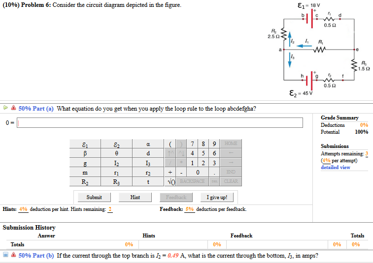
Solved Consider the circuit diagram depicted in the figure ...
0 Response to "42 consider the circuit diagram depicted in the figure."
Post a Comment