37 hunter pro c wiring diagram
Route valve wires between control valve location and controller. 2. At valves, attach a common wire to either solenoid wire of all valves. This is most commonly ...40 pages Hunter pro c wiring diagram. This feature will recognize the correct number of stations without having to reset or cycle power to the controller. Pro c components wiring cabinet. View and download hunter pro c owners manual and installation instructions online. Need help installing rachio 2nd gen hunter pro c support with hunter pro c wiring ...
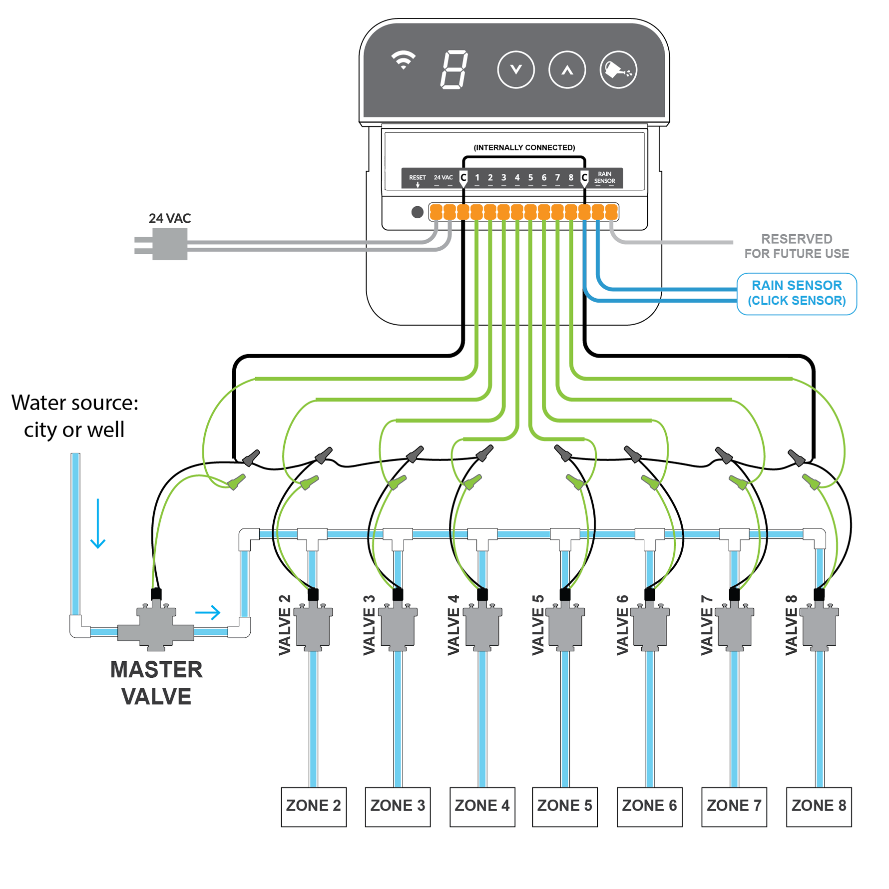
Hunter pro c wiring diagram. Hunter pro c sen 3 pro c rain sensor to valves sen rem ac2 ac1 gnd power supply 2 1 pmv com serialbrick irrigation note. Its easy to install or replace an irrigation sprinkler controller. The pro c utilizes automatic module recognition firmware to identify when pcm modules are installed or removed from the controller.
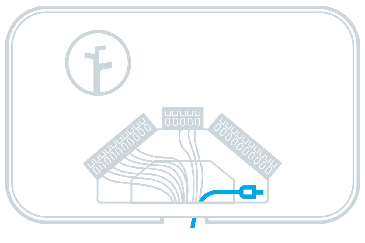
Hunter pro c wiring diagram
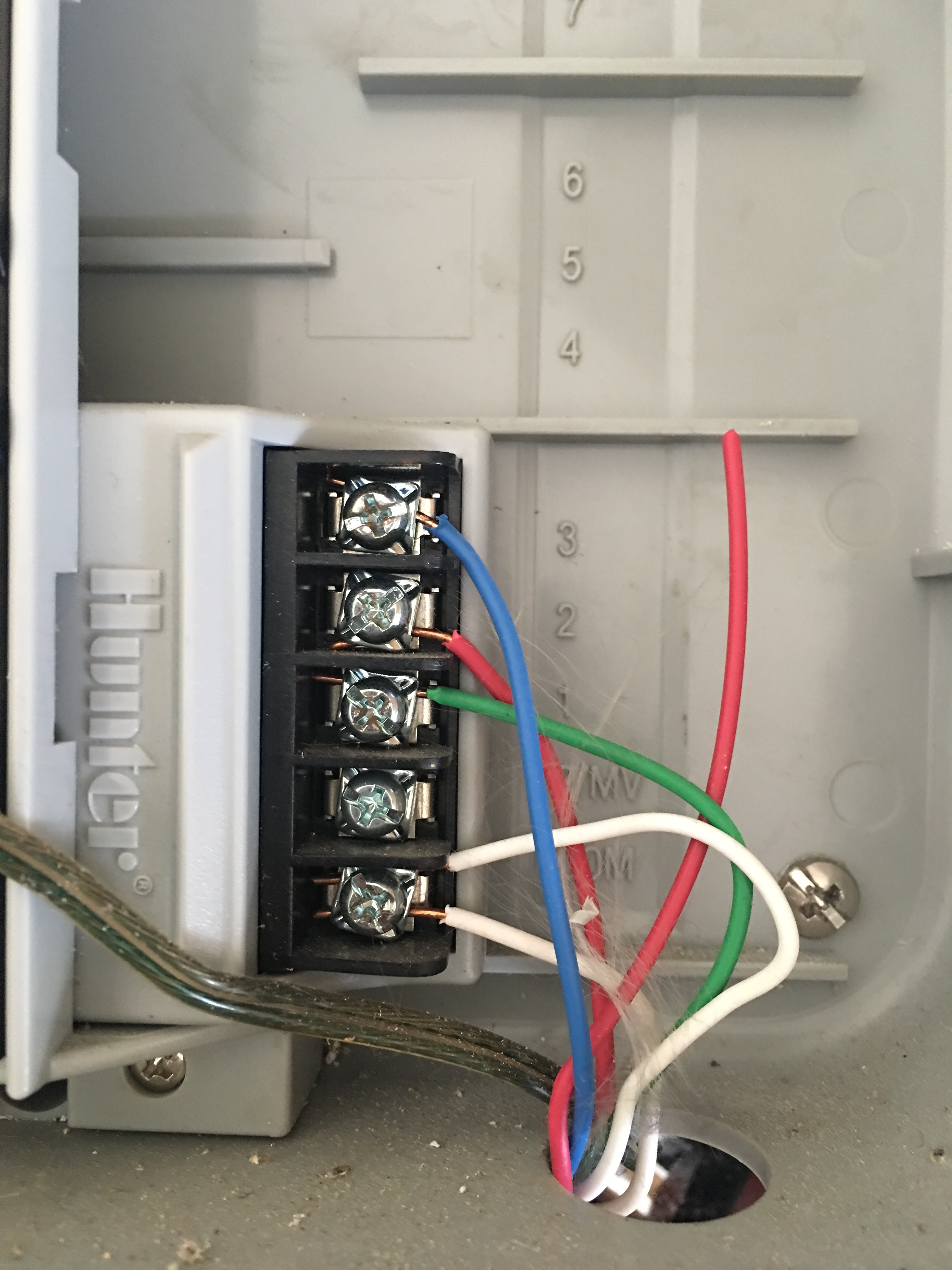
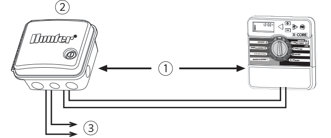
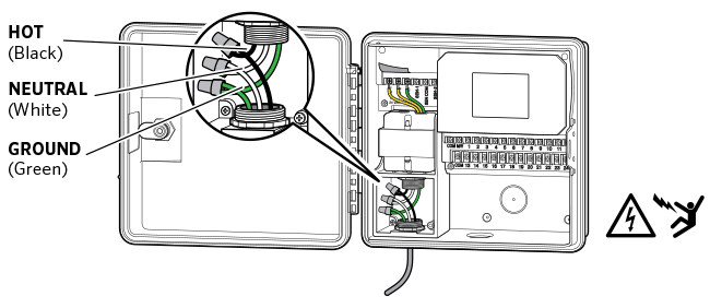
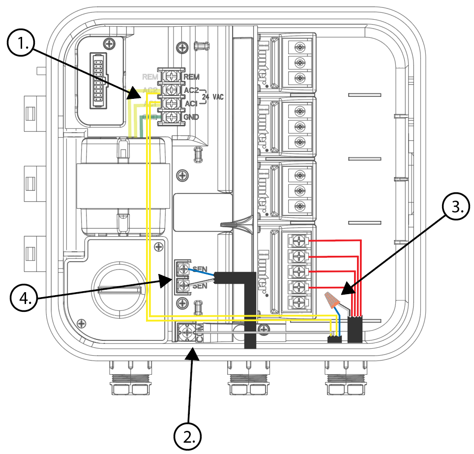
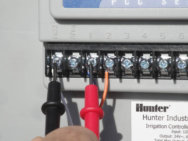
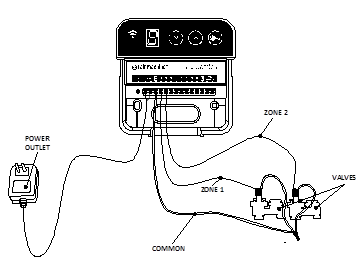
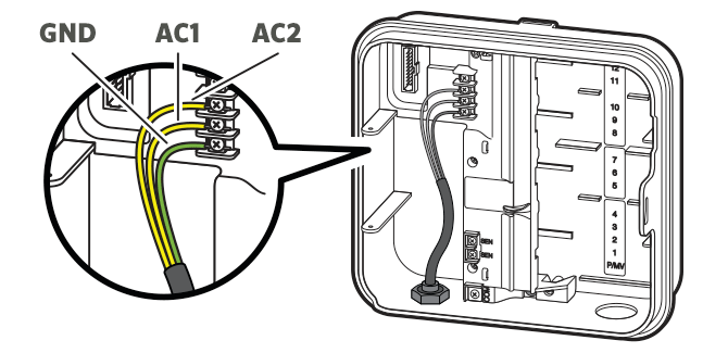
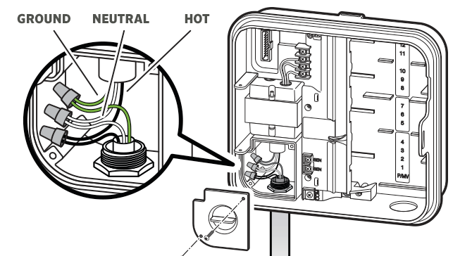
How to Connect Hunter Pro-C Station Wires. September 24, 2018. Image courtesy of hunter industries. Route valve wires between control valve location and controller. At valves, attach a common wire to either solenoid wire of all valves. This is most commonly a white colored wire. Attach a separate control wire to the remaining wire of each valve. Description : Pro-C – Connecting A Master Valve | Hunter Industries inside Hunter Pro C Wiring Diagram, image size 670 X 537 px. Actually, we have been noticed that hunter pro c wiring diagram is being just about the most popular field right now. So we attempted to locate some great hunter pro c wiring diagram picture for your needs. Route transformer cable through the hole on the bottom left side of the controller and connect one Yellow Wire to each of the screws marked AC and the Green ...
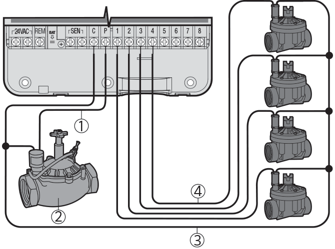
Hunter pro c wiring diagram. Hunter.Industries.is.pleased.to.introduce.the.Pro-C.Professional. ... The.controller's.cabinet.provides.ample.room.for.wiring..And.the.40 pages Pro-C - Connecting Station Wires. Route valve wires between control valve location and controller. At valves, attach a common wire to either solenoid wire of all valves. This is most commonly a white colored wire. Attach a separate control wire to the remaining wire of each valve. All wire splice connections should be done using waterproof ... Connect either wire from Master Valve to the P/MV terminal at the base of module. Connect remaining wire to the “COM” (Common) terminal. Hunter Industries. How to connect hunter x core master pro c connecting station wires hcc power module wiring diagram controller guide irrigation src plus wire rs terminal from sprinkler pump valve hc solenoid valves and ac a x2 plug pack rain bird sensor only one 2 systems by dlane industries owner s reticulation for bore wi fi new install replacing no zones running clik getting wyze starter ...
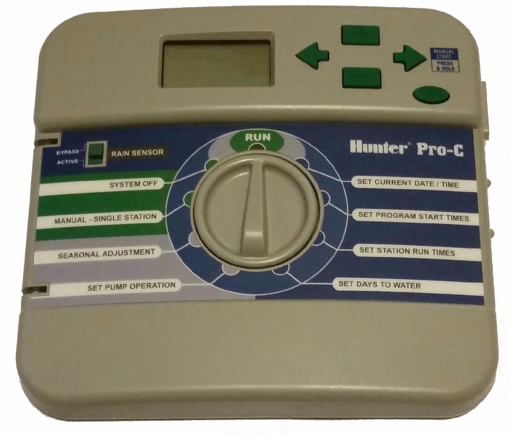
PRO-C®. Residential and Light Commercial. Irrigation Controller ... wiring. Pro-C/PCC controllers are intended to be supplied AC power with a.48 pages Hunter pro c manuals manuals and user guides for hunter pro c. Need help installing rachio 2nd gen hunter pro c support with hunter pro c wiring diagram image size 767 x 704 px and to view image details please click the image. Mounting the indoor controller to a wall 10. Replacing Hunter Pro C Wiring Rachio Community 01.12.2018. 01.12.2018. 3 Comments. on Hunter Sprinkler System Wiring Diagram. Refer to the diagram below when connecting your solenoid valves to the controller. Water main Take one wire from each solenoid, twist together and connect to the common (usually white) wire of your multicore irrigation cable. All wire. Hunter Pro-C => Pro-HC. I currently have a PRO-C installed on my house. Link. ... (6 sets of 4 emitters, diagram below) but after I add more the pressure drops too much and they work sub-optimally, i.e. just a trickle rather than a water spray.
To Controller. Pre-assembled. Assembled. The Pro-C controller is shipped with a SmartPort® wiring harness, allowing for fast and easy use of the Hunter controls ...32 pages Pro-C - Troubleshooting Guide · Wrong smartport wiring · Faulty pump relay or master valve wiring. · Incompatible or defective relay of solenoid. · Under sized wire ...Missing: diagram | Must include: diagram From the thousands of photos on the internet with regards to hunter pro c wiring diagram, selects the best libraries together with ideal image resolution exclusively for you all, and now this images is usually considered one of graphics series in your finest pictures gallery about Hunter Pro C Wiring Diagram.I hope you’ll want it. This particular picture (Pro-C – Connecting A Master Valve ... Route transformer cable through the hole on the bottom left side of the controller and connect one Yellow Wire to each of the screws marked AC and the Green ...
Description : Pro-C – Connecting A Master Valve | Hunter Industries inside Hunter Pro C Wiring Diagram, image size 670 X 537 px. Actually, we have been noticed that hunter pro c wiring diagram is being just about the most popular field right now. So we attempted to locate some great hunter pro c wiring diagram picture for your needs.
How to Connect Hunter Pro-C Station Wires. September 24, 2018. Image courtesy of hunter industries. Route valve wires between control valve location and controller. At valves, attach a common wire to either solenoid wire of all valves. This is most commonly a white colored wire. Attach a separate control wire to the remaining wire of each valve.
3kw 4 5kw Home Steam Machine Steam Generator Sauna Dry Steaming Furnace Wet Steam Steamer Digital Controller Sauna Machine Humidifiers Aliexpress









0 Response to "37 hunter pro c wiring diagram"
Post a Comment