37 in the diagram to the right the current through
A direct current circuit may contain capacitors and resistors, the current will vary with time When the circuit is completed, the capacitor starts to charge The capacitor continues to charge until it reaches its maximum charge (Q = Cε) Once the capacitor is fully charged, the current in the circuit is zero A wire loop travels to the right at a constant velocity. Which plot best represents the induced current in the loop as it travels from left of the region of magnetic field, through the magnetic field, and then entirely out on the right side? A wire loop travels to the right at a constant velocity. Which plot best represents the induced current in
The diagram at the right depicts a conducting wire. Two cross-sectional areas are located 50 cm apart. Every 2.0 seconds, 10 C of charge flow through each of ...
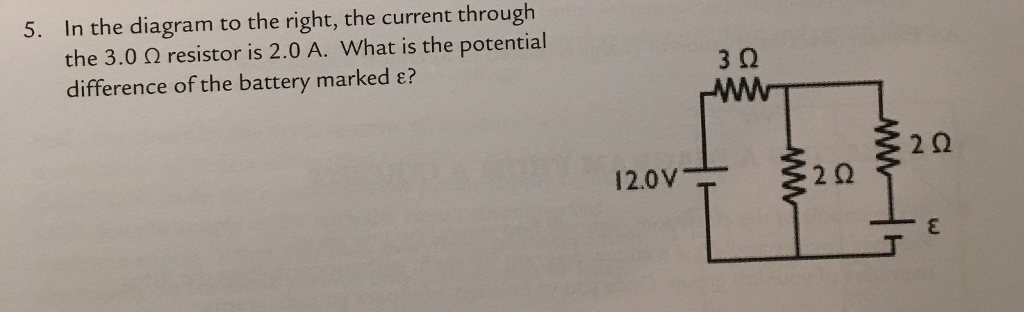
In the diagram to the right the current through
As Q increases I decreases, but Q changes because there is a current I. As the current decreases Q changes more slowly. I = dQ/dt, so the equation can be written: ε - R (dQ/dt) - Q/C = 0 This is a differential equation that can be solved for Q as a function of time. The solution (derived in the text) is: Q(t) = Q o [ 1 - e-t/τ] Click here to get an answer to your question ✍️ A current of 0.1 A flows through a 25 Ω resistor represented by the circuit diagram. The current in the ...1 answer · Top answer: Total resistance along 0.1 A 1R = 120 + 160 R = 15Ω Total resistance = 15 + 25 = 40 Ω Now the current distribute inverse to resistance 0.1I = 2040 ... Transcribed image text: Given the circuit below with 3 A of current running through the 4 Ω resistor as indicated in the diagram to the right. Determine... 8. 1Ω a. the current through each of the other resistors b. the voltage of the battery on the left, and c. the power delivered to the circuit by the battery 20 32 on the right 20V 3A40 Determine the current through each resistor in the ...
In the diagram to the right the current through. magnet is dropped through. Wire #2 (length 2L) forms a two-turn loop, and the same magnet is dropped through. Compare the magnitude of the induced currents in these two cases. (a) I 1 = 2 I 2 (b) I 2 = 2 I 1 (c) I 1 = I 2 ≠ 0 (d) I 1 = I 2 = 0 (e) Depends on the strength of the magnetic field Voltage doubles, but R also doubles, leaving ... Answer: E. Current is the ratio of charge to time. The quantity of charge passing through a cross section in 2 seconds is 10 C. The ratio of charge to time is. I = Q / t = ( 10 C) / ( 2 s) = 5 C/s = 5 Ampere. 6. Use the diagram at the right to complete the following statements: In this case, the current through each resistor is the same, ... Questions 6 and 7 refer to the following: The diagram to the right represents an electric ...10 pages all current goes through inductor in direction shown The switch in the circuit shown has been closed for a long time. At t = 0, the switch is opened. Calculation C R L V I L Current through inductor immediately after switch is opened is the same as the current through inductor immediately before switch is opened Electricity & Magnetism Lecture ...
Q. If the current through the battery was 10A in this diagram. What would the current through each bulb be? answer choices . 10A. 5A. 20A. 0A. Tags: Question 5 . SURVEY . 60 seconds . Q. If the current through the battery was 10A in this diagram. Q T 1 T 2 L Q T 2 T T 1 Q L x 0 T 2 (a) Heat flow (b) Electric current flow R R e V 2 T 1 V 1 T 1 – T 2 ——— R Q = · V 1 – V 2 ——— R e I = FIGURE 3–3 Analogy between thermal and electrical resistance concepts. which is the ratio of the driving potential T to the corresponding transfer rate cond, wall. This equation for heat ... If n electrons pass through the cross-section of a conductor in time t, the total charge that passes through the conductor is then, Q = n×e. Electric Current and Circuit Diagram Elements. The schematic diagram represents the different components of a circuit; this is the circuit diagram. These symbols represent the common electrical components ... Transcribed image text: Given the circuit below with 3 A of current running through the 4 Ω resistor as indicated in the diagram to the right. Determine... 8. 1Ω a. the current through each of the other resistors b. the voltage of the battery on the left, and c. the power delivered to the circuit by the battery 20 32 on the right 20V 3A40 Determine the current through each resistor in the ...
Click here to get an answer to your question ✍️ A current of 0.1 A flows through a 25 Ω resistor represented by the circuit diagram. The current in the ...1 answer · Top answer: Total resistance along 0.1 A 1R = 120 + 160 R = 15Ω Total resistance = 15 + 25 = 40 Ω Now the current distribute inverse to resistance 0.1I = 2040 ... As Q increases I decreases, but Q changes because there is a current I. As the current decreases Q changes more slowly. I = dQ/dt, so the equation can be written: ε - R (dQ/dt) - Q/C = 0 This is a differential equation that can be solved for Q as a function of time. The solution (derived in the text) is: Q(t) = Q o [ 1 - e-t/τ]
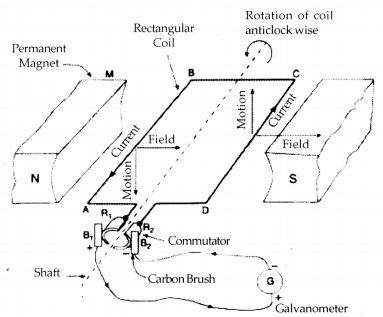
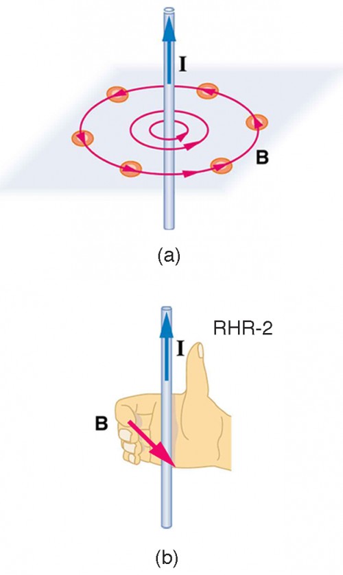
State Fleming S Right Hand Rule With A Labelled Diagram Describe The Working Of On A C Electric Generator Cbse Class 10 Science Learn Cbse Forum

The Diagram Below Shows A Straight Wire Carrying A Conventional Current Into The Page The Wire Homeworklib
2
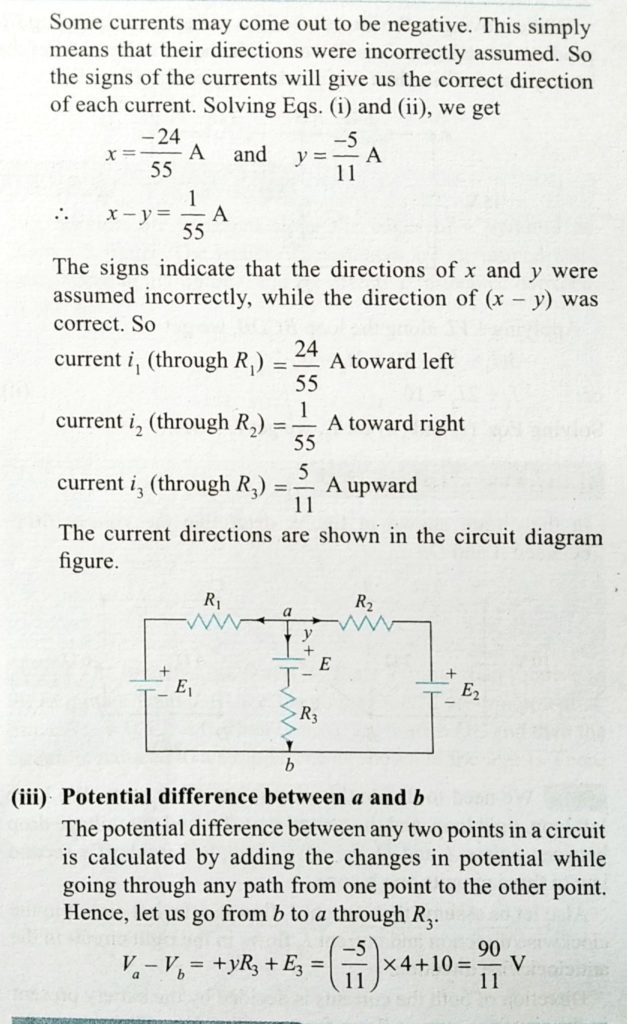
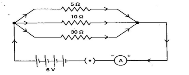
Calculate The Current Through Each Resistance In The Given Circuit Also Calculate The Potential Difference Between The Points A And B E1 6v E2 8v E3 10v R1 5w R2 10w R3
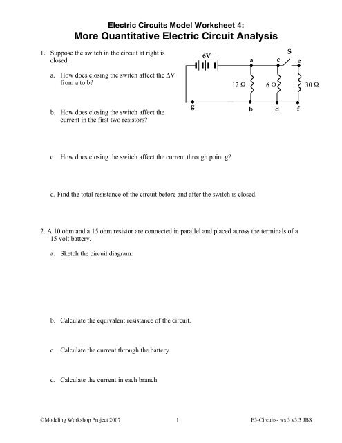
More Quantitative Electric Circuit Analysis Modeling Physics
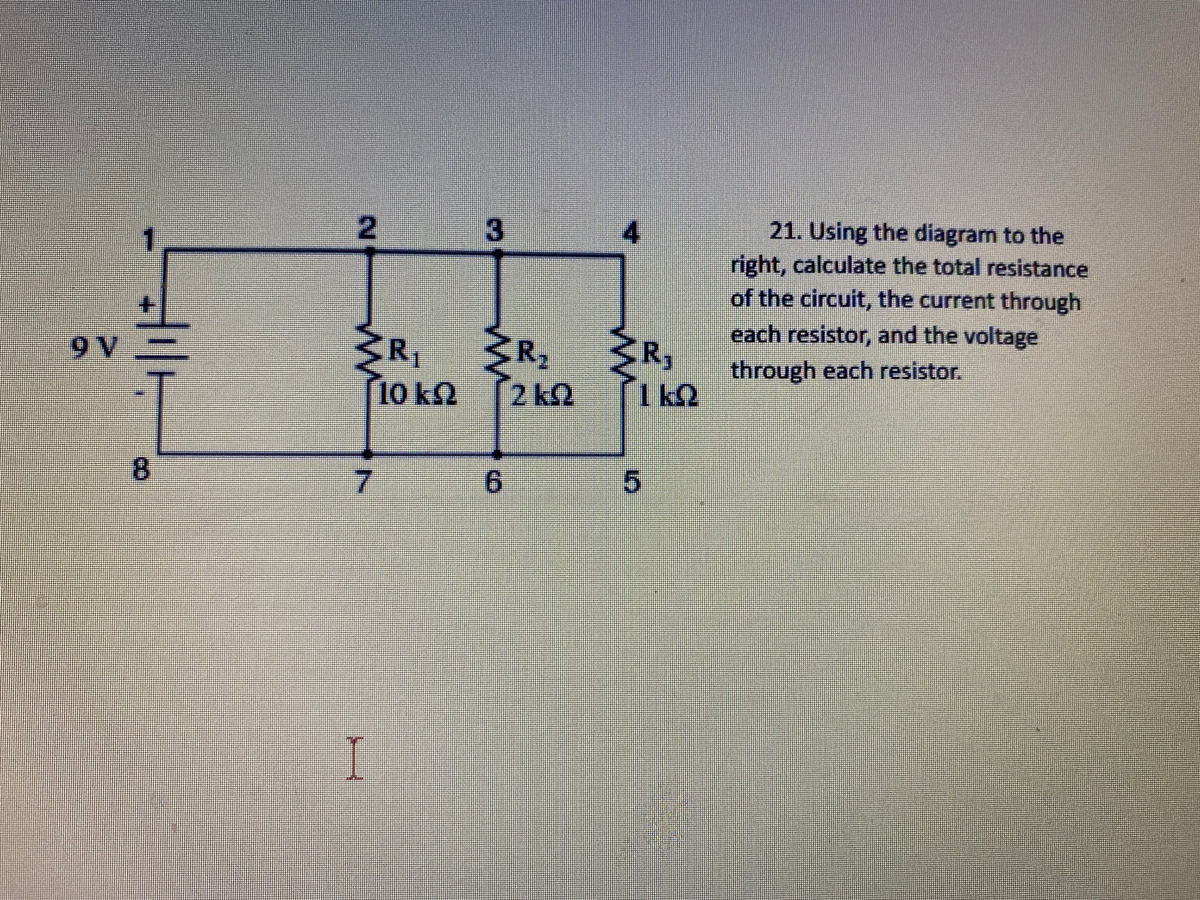
Answered 3 21 Using The Diagram To The Right Bartleby
Plos One Characteristics Of The Norwegian Coastal Current During Years With High Recruitment Of Norwegian Spring Spawning Herring Clupea Harengus L
Solved In The Diagram To The Right The Current Through The Chegg Com

High Magnetic Fields For Fundamental Physics Cern Document Server

Class 10 Science Chapter 13 Ncert Exemplar Solution Part Iii

Uses Of Radioactivity Edexcel Igcse Double Science Physics Revision Notes
1

Mathematics Free Full Text A Second Order Well Balanced Finite Volume Scheme For The Multilayer Shallow Water Model With Variable Density Html
Magnetic Fields Produced By Currents Ampere S Law Physics
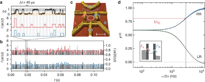
Measurement Of Finite Frequency Current Statistics In A Single Electron Transistor Nature Communications

Right Hand Rule For Current Carrying Wire Ap Physics 2
2
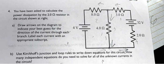
Solved You Have Been Asked T0 Calculate Dowei Dissipation By The 2 0 02 Resistor The Circuit Shown At Right 8 0 Q 3 0 Q Draw Arrows On The Diagram To Indicatc Your Best Gucss
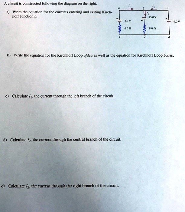
Solved Circuit Is Constructed Following The Diagram On The Right Write The Equation For The Currents Entering And Exiting Kirch Hoff Junction Iso Jov 600 809 Write The Equation For The Kirchhoff Loop
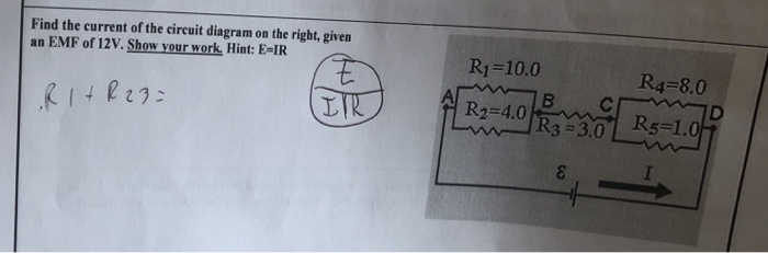
Solved Find Current Circuit Diagram Right Given Emf 12v Show Work Hint E Ir R1 100 R4 80 R2 40 Q30221049 Essaytaste
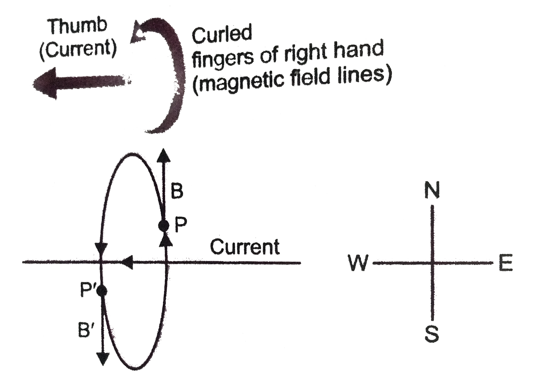
A Current Through A Horizontal Powerline Flows In East To West
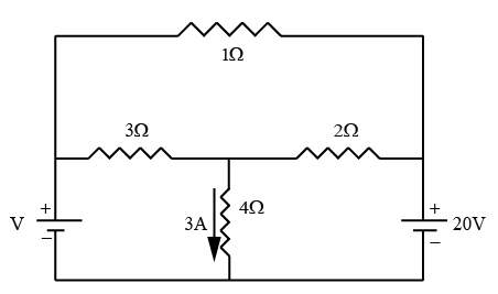
Given The Circuit Below With 3a Of Current Running Through T 03ad7910

Dc And Ac Bias Dependence Of Mlcc Capacitors Including Temperature Dependence Passive Components Blog

Relationship Between Sensor Response Absolute Value Of Current Across Download Scientific Diagram

Will Rate For Correct Answer Thank You R R2 B On The Diagram Above Label Your Prediction For The Direction Of Curren Homeworklib
Solved En Hw A Model For Circuits Part 3 Multiple Batteries Name The Circuit Diagram From The Previous Page Is Reproduced At Right X For Your Conv Course Hero
For The Circuit Shown In The Diagram Given Below Calculate Left Iright The Value Of Current Through Each Resistor Left Iiright The Total Current In The Circuit Left Iiiright The Total Effective Resistance Of The

By Using Thevinins Theorem De See How To Solve It At Qanda
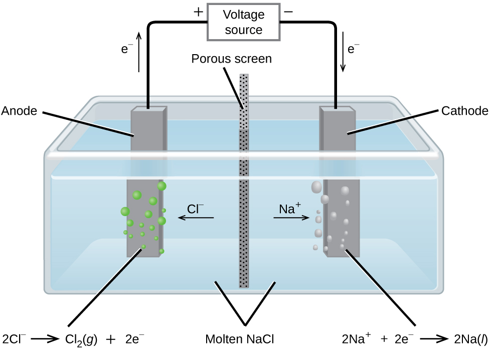
17 7 Electrolysis Chemistry
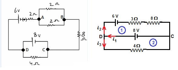
What Will Be The Current Through 8 And 4 7ujw4v33 Physics Topperlearning Com
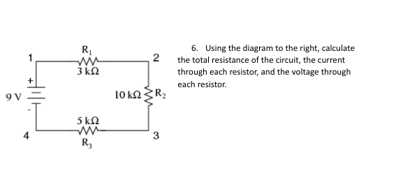
Answered R1 6 Using The Diagram To The Right Bartleby
1
Carnegie Institution Of Washington Publication The Calorimeter 41 Fig 21 Diagram Of Wiring Of Circuits Actuating Plunger And Creeper The Bar Is In Contact With The Slide Wire J And Therefore Varies The

Part A What Is The Current Through The 10 Omega Resistor In The Figure Figure 1 Express Your Answer To Two Significant Figures And Include The Appropriate Units Part B Is

3 The Diagram Below Shows A Circuit With One Battery And 10 Resistors 5 On The Left And 5 On The Right Determine A The Current Through B The Voltage Drop Across

3 The Diagram Below Shows A Circuit With One Battery And 10 Resistors 5 On The Left And 5 On The Right Determine A The Current Through B The Voltage Drop Across
Solved Problem Solving 1 The Diagram Below Shows A Circuit With One Battery And 10 Resistors 5 On The Left And 5 On The Right Determine A The C Course Hero
0 Response to "37 in the diagram to the right the current through"
Post a Comment