40 abb ach550 wiring diagram
Diagram #4 Diagram #2 Diagram #3 For manual switch wiring, refer to switch manufacturer instructions. Step 1 Disconnect the battery Mar 20, 2009 · Joined Apr 30, 2007. This manual switch serves as a bypass to the thermal switch and will operate the fans at any temperature. The fan will turn on automatically when the temperature guage gets to the 3/4 mark, but that is way too hot. That would ... Connection Diagrams – Standard E-Bypass (R7/R8, Floor Mounted) ACH550 Standard E-Bypass units are configured for wiring access from the top. The following figure shows the Standard E-Bypass (floor mounted) wiring connection points. Refer to the ACH550-UH User's Manual for control connections to the drive. BP0056 ACH550 Input Power Ground Lug ...
ABB type IEC 60269 A A A A2s V size 3-phase UN = 230 V 144A-2 1700 144.0 200 300000 500 OFAF0H200 0 171A-2 2300 171.0 250 600000 500 OFAF0H250 0 213A-2 3300 213.0 315 710000 500 OFAF1H315 1 276A-2 5500 276.0 400 1100000 500 OFAF2H400 2 3-phase UN = 400 or 480 V 145A-4 1700 145 160 185000 500 OFAF00H160 00
Abb ach550 wiring diagram
Abb Ach550 Wiring Diagram. For information on ABB product training, navigate to wiringall.com and select The macro wiring diagrams for each macro earlier in this chapter use an. ACH User's Manual. ACH Drives ACH Drive manuals Application macros and wiring. 6. ACH550-01/UH User's Manual. (0.75…90 kW) / (1…150 HP). • Safety. • Installation. • Start-Up. • Diagnostics. • Maintenance. • Technical Data. ACH550-02/U2 ...62 pages ACH550 BACnet User's Manual. Installation. Control Interface. In general, the basic control interface between the fieldbus system and the drive consists of:.32 pages
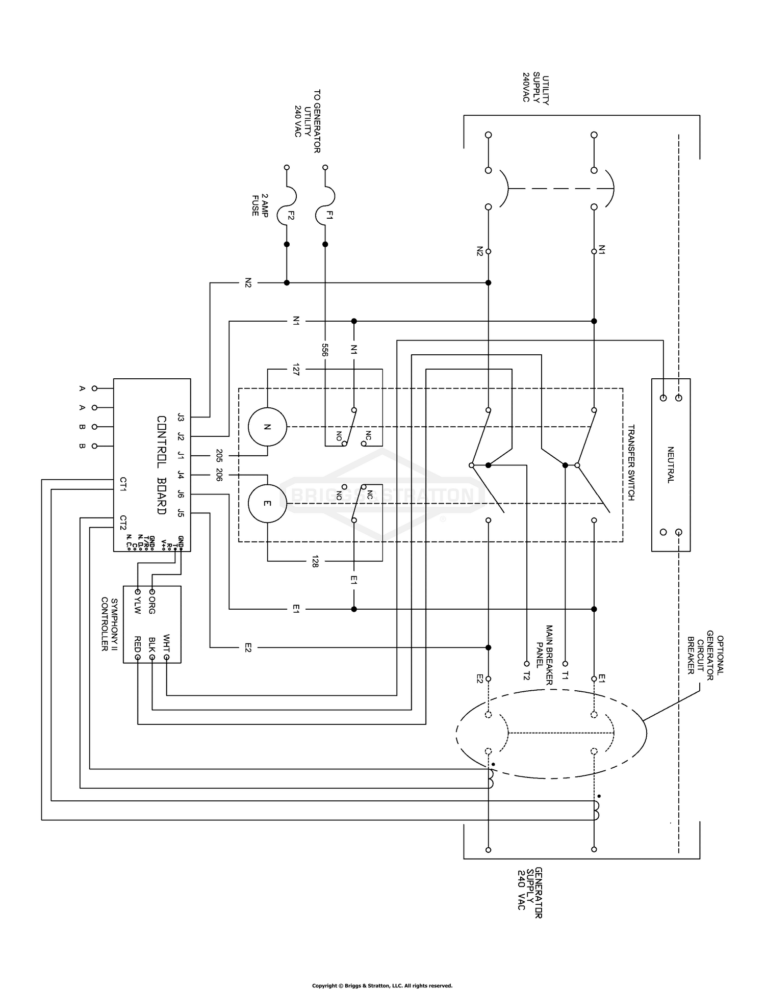
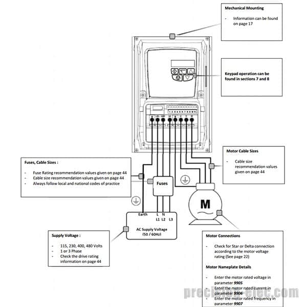
Abb ach550 wiring diagram. Wiring overview Connection diagrams – standard drive with input disconnect (wall mounted) The following figure shows the Standard Drive with Input Disconnect (wall mounted) wiring connection points. Refer to the ACH550-UH User’s Manual page 1-317 for control connections to the drive. ACH550 Input Power Terminals Motor Terminals Ground Lug(s) Installation. The following is a typical power diagram. Installation Flow Chart. The installation of Classic Bypass Configurations for ACH550 drives follows ...34 pages ACH550 Installation, Operation and Maintenance Manual. ACH550-UH. Connection diagrams. The following diagrams show: • The terminal layout for frame size R3, ...104 pages ii | ACH550 Product Bulletin ... control circuit connection diagram for each macro. ... wiring cost savings and savings in the number of I/O.56 pages
ABB's offering for redundant HVAC Drives is a pair of ABB ACH550 drives, integrated ... control wiring to primary and secondary systems.2 pages Abb Ach550 Wiring Diagram Download. abb ach550 wiring diagram - Building circuitry representations show the approximate places and also interconnections of receptacles, illumination, and also irreversible electrical services in a structure. Interconnecting wire paths may be revealed about, where particular receptacles or fixtures should get on a common circuit. 5. Install wiring WARNING! Ensure the motor is compatible for use with the ACH550. The ACH550 must be installed by a competent person. If in doubt, contact your local ABB sales or service office. Conduit kit Wiring R1…R6 drives with the UL type 1 Enclosure requires a conduit kit with the following items: • conduit box •screws • cover Size: 225.45 KB. Dimension: 1024 x 985. DOWNLOAD. Wiring Diagram Sheets Detail: Name: abb ach550 wiring diagram – Abb Vfd Control Wiring Diagram Additionally Air Conditioning Wire Rh Ayseesra Co Abb 150 Wiring. File Type: JPG. Source: nhrt.info.
6 Feb 2006 — The reader is expected to know the fundamentals of electricity, wiring, electrical components and electrical schematic symbols.476 pages 25.10.2018. 7 Comments. on Abb Ach550 Wiring Diagram. Installing the wiring (supplement to ACHUH User's Manual) Check E-Clipse Feedback from the ABB E-Clipse Bypass – EFB. .. Connection diagrams – Vertical E-Clipse Bypass. ACH Vertical. higher than m ( ft) above sea level, please contact your local ABB distributor or representative for ... Installing the wiring (supplement to ACH550-UH User’s Manual) WARNING! † Do not connect or disconnect input or output power wiring, or control wires, when power is applied. † Never connect line voltage to drive output Terminals T1, T2, and T3. † Do not make any voltage tolerance tests (Hi Pot or Megger) on any part of the unit. Welcome to our website, we try to bring you relevant images to what you are looking for about "Abb Ach Wiring Diagram". Therefore we present the picture gallery below. Hopefully what you are looking for can be found below. This image is the best image we collect from the best sources, the image below is the property of their official website ...
Ach550 Wiring Diagram
ACH550 BACnet User's Manual. Installation. Control Interface. In general, the basic control interface between the fieldbus system and the drive consists of:.32 pages
Abb Wiring Diagram - 88 Wiring Diagram
ACH550-01/UH User's Manual. (0.75…90 kW) / (1…150 HP). • Safety. • Installation. • Start-Up. • Diagnostics. • Maintenance. • Technical Data. ACH550-02/U2 ...62 pages
![[XN_7954] Breaker Abb Manual On Abb Power Circuit Breaker ...](https://static-assets.imageservice.cloud/326420/abb-drive-ach550-wiring-diagram-wiring-diagram.jpg)
[XN_7954] Breaker Abb Manual On Abb Power Circuit Breaker ...
Abb Ach550 Wiring Diagram. For information on ABB product training, navigate to wiringall.com and select The macro wiring diagrams for each macro earlier in this chapter use an. ACH User's Manual. ACH Drives ACH Drive manuals Application macros and wiring. 6.
Abb Hvac Vfd Wiring Diagram - Wiring Diagram and Schematic

Abb Ach550 Control Wiring Diagram - easywiring

Abb Ach550 Control Wiring Diagram - ELGAVONTROLLOP
Abb Ach550 Wiring Diagram

Abb Robot Wiring Diagram | Wiring Diagram Database
Wiring Diagram Acb Abb - HAFIZAHJAMILAHCOMMUNITY
.PNG)
Abb Ach550 Control Wiring Diagram - ELGAVONTROLLOP
Ach550 Wiring Diagram
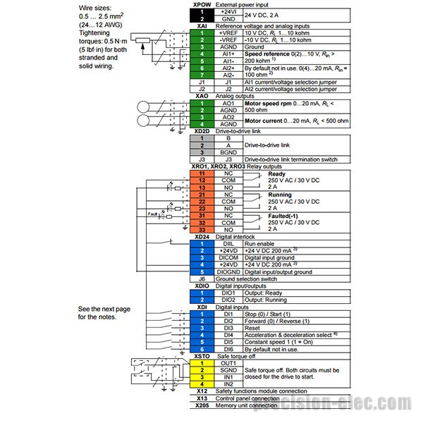
Abb Dc Motor Wiring Diagram

Abb Ach550 Control Wiring Diagram - ELGAVONTROLLOP

Abb Ai810 Wiring Diagram - Auto Electrical Wiring Diagram

Abb Ach550 Wiring Diagram - Wiring Diagram Networks
Abb Ai810 Wiring Diagram - Auto Electrical Wiring Diagram

Abb Vfd Acs550 Wiring Diagram - Wiring Diagram

Abb Vfd Acs550 Wiring Diagram - Wiring Diagram
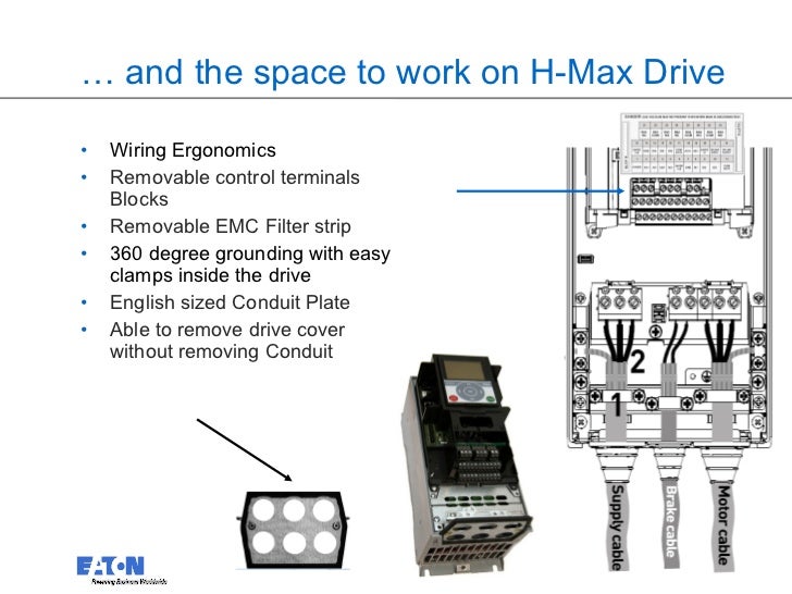
Abb Ach550 Wiring Diagram
abb ai810 wiring diagram - Wiring Diagram
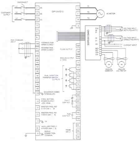
Saftronics GP10 - Analog I/O Interface Card
Buy ACS250-03U-02A2-4+B063 - 1 HP ABB ACS250 Micro VFD

Abb Wiring Diagram | Wiring Diagram Database

Download MP3 Acs550 Drive Manual 2018 Free

Patent US20130087319 - Automatic variable speed motor ...

Abb Ach550 Wiring Diagram | Free Wiring Diagram
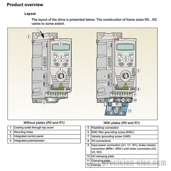
Abb Ach550 Wiring Diagram - Wiring Diagram Networks
Abb Ach550 Wiring Diagram
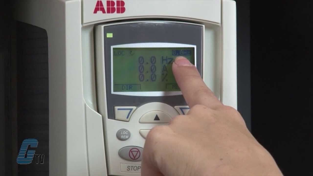
VFD control panel diagram and vfd working principle - YouTube

Abb Ach550 Wiring Diagram | Free Wiring Diagram
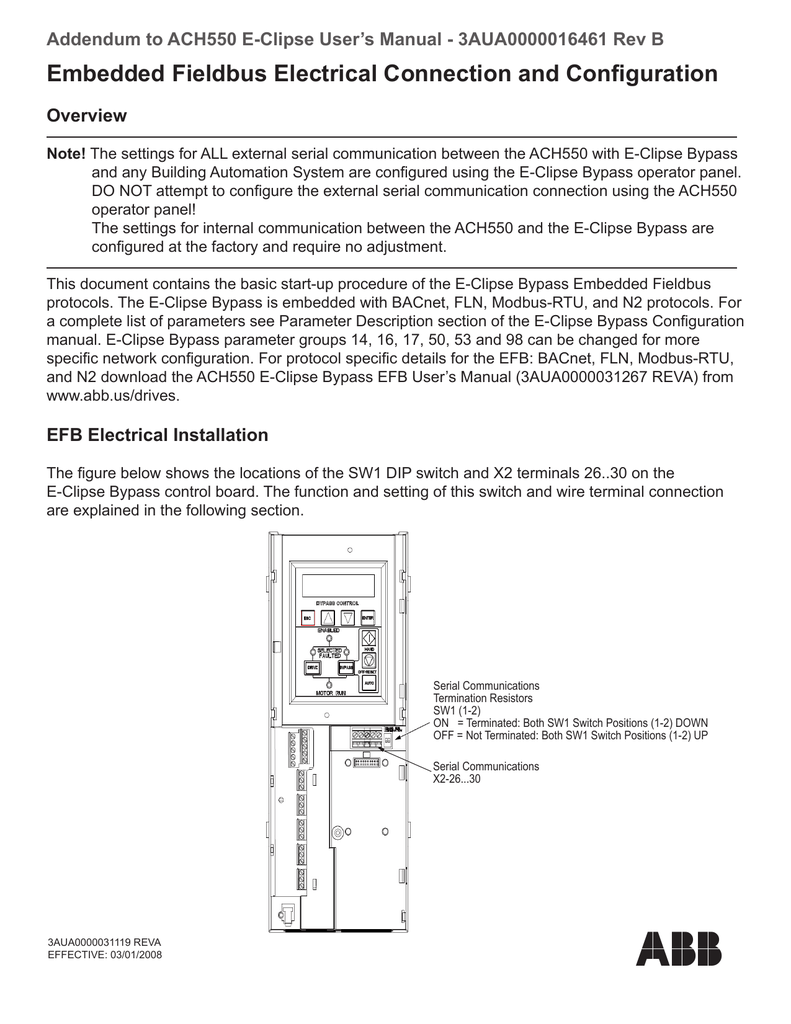
Abb Ach550 Control Wiring Diagram - easywiring
Abb Ach550 Spare Parts List | Reviewmotors.co
.png)
230V Micro VFD

19 Lovely Abb Acs550 Wiring Diagram

Abb Wiring Diagram - 88 Wiring Diagram

Abb Ach550 Control Wiring Diagram - easywiring

Abb Vfd Acs550 Wiring Diagram - Wiring Diagram
Abb Flow Meter Wiring Diagram - Wiring Diagram
![[DIAGRAM] Abb Ach550 Bacnet Wiring Diagram FULL Version HD ...](https://imgv2-1-f.scribdassets.com/img/document/68098834/original/080e9c0e94/1539637378?v=1)
[DIAGRAM] Abb Ach550 Bacnet Wiring Diagram FULL Version HD ...
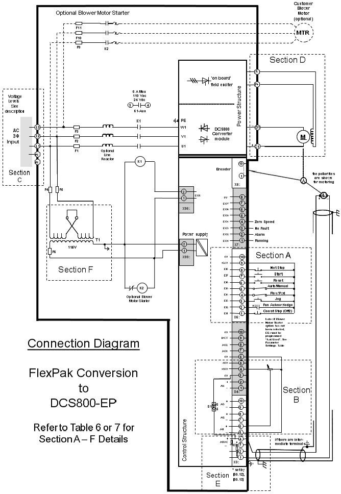
Abb DCS800-EP - Installation Procedure - Wiring and ...
0 Response to "40 abb ach550 wiring diagram"
Post a Comment