41 franklin electric control box wiring diagram
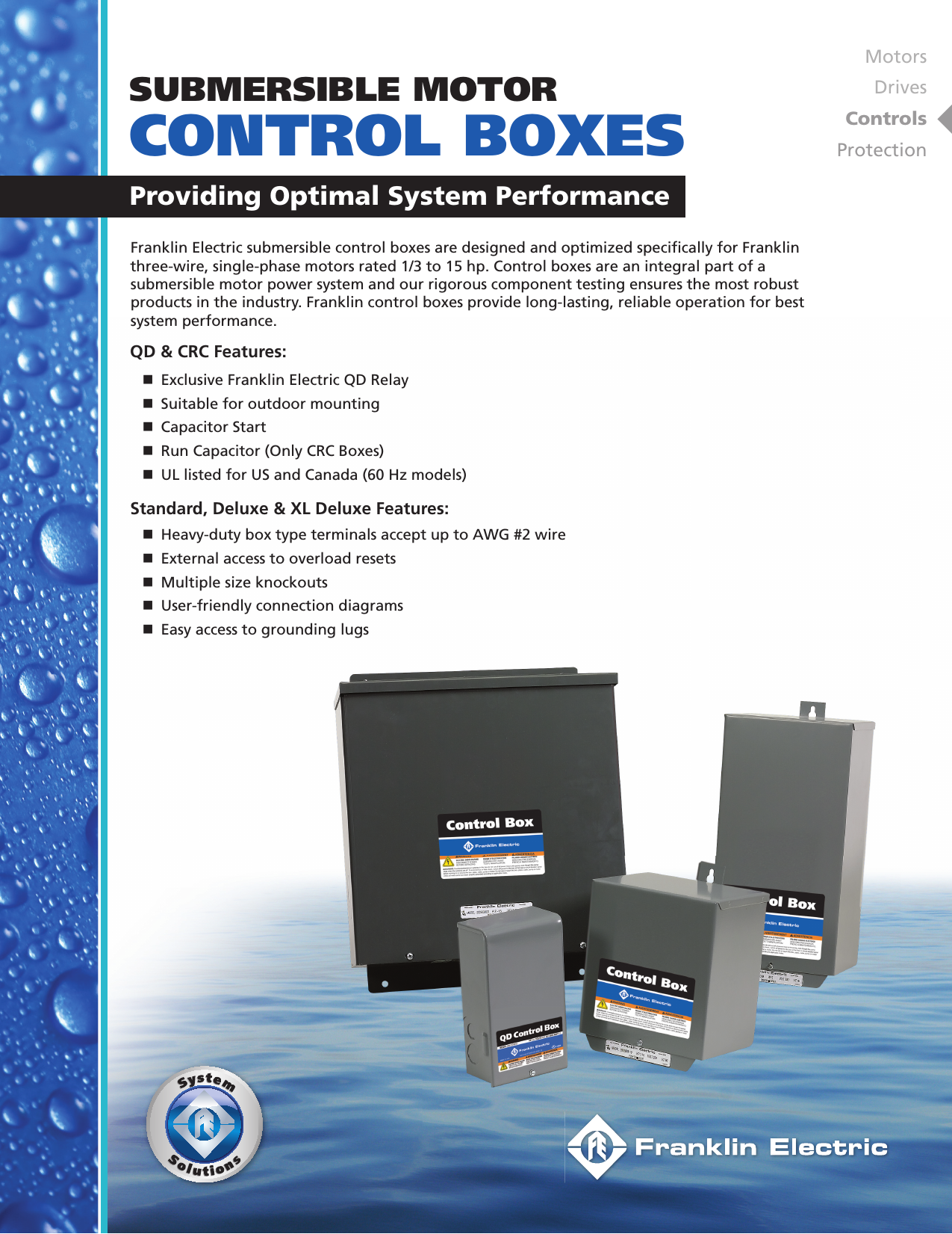
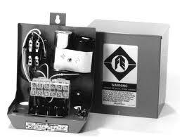
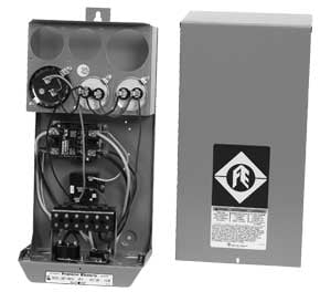
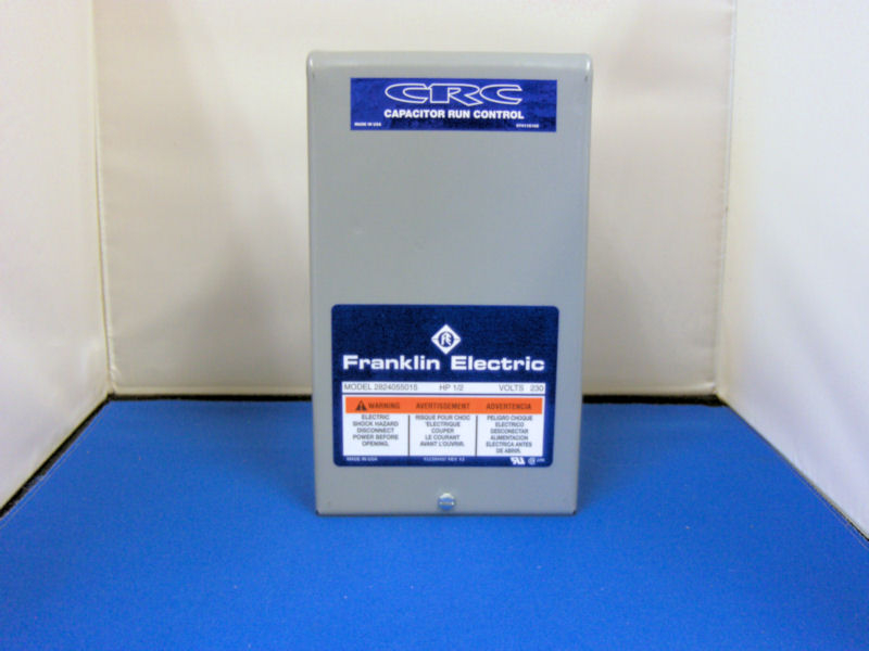
Franklin Electric 2145581903 Super Stainless Water Well Motor 4 1 0 Hp 220v 3 Wire Single Phase 50 Hz No Lead Fec2145581903. Single phase motors and controls franklin electric qd control box 1 hp 230v deluxe 2 little giant submersible motor 230 volts 3 wire vs 4 pump replacement 5hp 1hp crc water wiring troubleshooting installation operation manual diagram 4hp intelligent soft starter ... Control Boxes. Franklin Electric submersible control boxes are designed and optimized specifically for Franklin submersible motors. Controls are an integral part of a submersible motor power system and our rigorous component testing ensures the toughest products in the industry. Franklin controls provide long-lasting, reliable operation for best system performance.
View these Products: https://www.rcworst.com/Control-Boxes-c341.htmlFranklin Electric AIM Manual: https://www.rcworst.com/Shared/content/mfr/franklin_electri...

Franklin electric control box wiring diagram
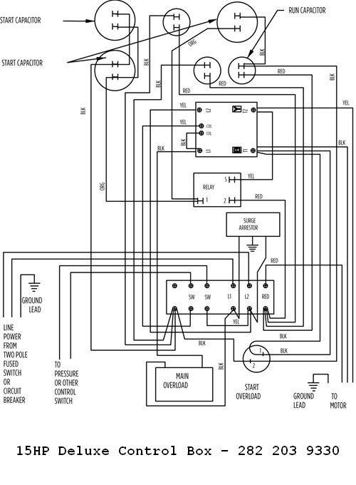
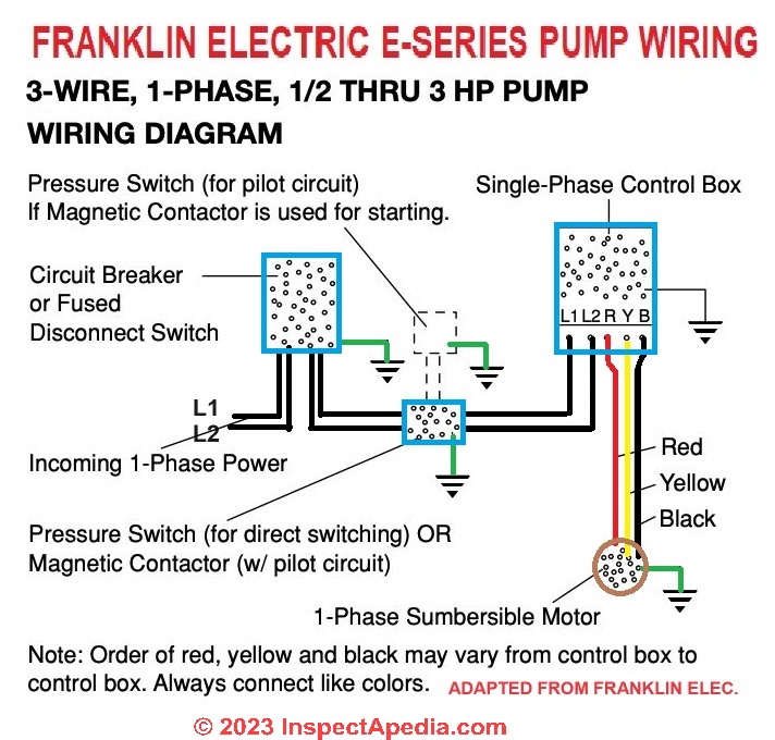
Franklin Electric Well Pump Control Box Wiring Diagram- wiring diagram is a simplified standard pictorial representation of an electrical circuit.It shows the components of the circuit as simplified shapes, and the capability and signal connections with the devices. Diagram Mitsubishi M64 Wiring Full Version Hd Quality Diagramofbrain Andreapendibene It. Vmc Submersible Motor Control Model 14940951 V 230 S F Max Amp 10 4 Hp 1 59 99 Picclick. Franklin Electric 2801044915 Qd Submersible Motor Control Box 0 5 Hp 115v 1ph For 3 Wire Motors Fec2801044915. Aim Manual Page 55 Single Phase Motors And Controls Motor ... Control Box Wiring Diagrams. LINE POWER. FROM TWO POLE. FUSED SWITCH OR. CIRCUIT BREAKER,. AND OTHER CONTROL. IF USED. OVERLOAD. 275411114.
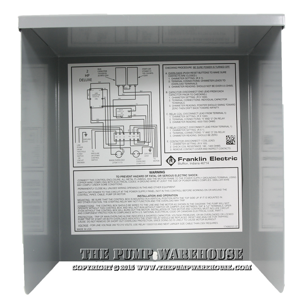
Franklin electric control box wiring diagram. Franklin Electric Well Pump Control Box Wiring Diagram from redlionproducts.com Effectively read a wiring diagram, one offers to learn how typically the components inside the method operate. For instance , if a module will be powered up also it sends out a signal of half the voltage and the technician would not know this, he'd think he has a ... Franklin 2HP 230V Standard Control Box. Type: CONTROL BOX, STANDARD. HP: 2. Volts: 230. HZ: 60. Model No: 2823018110. 2HP Standard 282 301 8110 Control Box Wiring Diagram. Franklin Standard Control Box Parts Breakdown. Franklin Electric Control Boxes Are In Stock and Ship "FREE". This Franklin Electric submersible control boxes are designed and optimized ... Metal Version; Includes Starting Capacitor; Manual Reset Overload ... Sep 29, 2020 - Franklin Electric Control Box Wiring Diagram . Franklin Electric Control Box Wiring Diagram . Submersible Pump Control Box Wiring Diagram Image. Wiring Diagram Franklin Electric Control Box Refrence Wiring Diagram. 3 Wire Well Pump Wiring Diagram Sample
• Control Box Wiring Diagrams. Cookies: Our website uses cookies for analytics and to enable dynamic content.Learn More 1/3 to 1HP QD Control Box Wiring Diagram · Franklin QD Control Box Parts Breakdown. Franklin Electric Control Boxes Are In Stock and Ship "FREE" ... Single Phase Submersible Pump Starter Wiring Diagram 3 Wire Well - 3 Wire Well Pump Wiring Diagram. Wiring Diagram includes many detailed illustrations that display the relationship of various items. It consists of directions and diagrams for different types of wiring techniques as well as other items like lights, windows, and so forth. Wire Diagram For A Franklin Electric Submergible Pump Fixya. Aim Manual Page 55 Single Phase Motors And Controls Motor Maintenance North America Water Franklin Electric. Franklin Electric 21450790 4 Super Stainless Pump Motor 0 75 Hp 230v 1ph 3 Wire Fec21450790. Franklin 55kw 4 Motor And Lowara Pump 1gsl05 Control Box Water Parts Direct.
Franklin Electric Submersible Pump Motor Controllers The Standard & Deluxe motor control boxes are designed for use with Franklin Electric 3-wire (AKA: 3 Wires plus 1 Ground Wire ), single-phase submersible motors. These control boxes are recommended for water systems that use pressure switches, level switches, or other pilot devices. Congratulations on your purchase of a Franklin Electric pump protection system. Pumptec-Plus is the most ... The control box provides large terminal blocks and plenty of room for wiring, even when using #2 wire. ... and plenty of room for wiring, even when using 25mm wire. Our unique Snapshot calibration feature pro- Franklin Electric Motor Wiring Diagram from static-cdn.imageservice.cloud Print the wiring diagram off plus use highlighters to trace the signal. When you make use of your finger or perhaps the actual circuit with your eyes, it is easy to mistrace the circuit. 1 trick that We 2 to printing a similar wiring plan off twice. Franklin Control Box Wiring Diagram Aim Manual Page 53 Single Phase Motors and Controls Motor. Franklin Control Box Wiring Diagram - wiring diagram is a simplified welcome pictorial representation of an electrical circuit. It shows the components of the circuit as simplified shapes, and the capability and signal contacts with the devices.

Aim Manual Page 54 Single Phase Motors And Controls Motor Maintenance North America Water Franklin Electric
Application • Installation • Maintenance Manual ... STANDARD CONTROL BOX WIRING DIAGRAMS ... Franklin Electric submersible motors are.
5HP Deluxe 282 113 9310 Control Box Wiring Diagram · Franklin Deluxe Control Box Parts Breakdown. Franklin Electric Control Boxes Are In ...
Submersible Motor Franklin 4 3 4 Hp 1 Phase 2145579204s Control Box Sentral Pompa Solusi Pompa Air Rumah Dan Bisnis Anda
1 1/2HP 282 300 8110 Control Box Wiring Diagram Newer . Franklin Standard Control Box Parts Breakdown . Franklin Electric Control Boxes Are In Stock and Ship "FREE" Product Reviews Write A Review. Comments. No reviews yet, be the first to review this product! Product Q & A.
Franklin Electric 5800060100 Pumptec Plus Motor Protection Device 230v 1 Phase 1 2 5 Hp . Franklin Electric Submersible Pump Manual . 2hp 230v Standard Control Box . Electric Motor Hp Chart Yobi Karikaturize Com . Aim Manual Page 54 Single Phase Motors And Controls . Electric Motor Wiring Diagram Capacitor Wiring Diagram
Franklin Electric Franklin Electric 5870203110 Monodrive Submersible Motor Constant Pressure Controller Nema1 Fec5870203110
Franklin Electric Control Box Wiring Diagram. Franklin Electric 21450590 4 Super Stainless Pump Motor 0 5 Hp 230v 1ph 3 Wire Fec21450590. The QD in QD Control Box comes from Quick-Disconnect. 12 - 1 hp CRC QD RELAY 40_ Sixth digit depends on. Control Box Wiring Diagrams. 1 - hp Date Codes 11C19 Older. Pumptec-Plus is the most.
symbol on your pump or in this manual, look for ... FRANKLIN ELECTRIC RECOMMENDATIONS, MAY ... wiring diagram in the control box to avoid damage to.
In the case of Franklin Electric Control Boxes, there's much more to the a surge arrestor, protecting the QD Relay and the motor from electrical. Control Box Wiring Diagrams. 1/3 - 1 hp QD RELAY 10_ Sixth digit depends on hp. 1/2 - 1 hp CRC QD RELAY 40_ Sixth digit depends on .
Wiring diagram franklin electric control box. Gemini gem rp1cae2 gemini gem k1ca. This refers to a european sizing that is measured in millimeter squared mm2. The number wire size varies from 05 to 60. At 1426 the ship was attacked by japanese planes. The kit comes with two installation screws and the element.
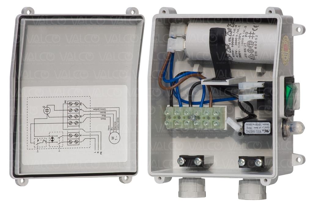
Single-phase submersible pump control box wiring diagram - 3 wire submersible pump wiring diagram. In the submersible pump control box, we use a capacitor, a resit-able thermal overload, and a DPST switch (double pole single throw). The wiring connection of the submersible pump control box is very simple. Here is the complete guide step by step.
Franklin 3/4Hp 230V Crc Control Box - Franklin Electric Control Box Wiring Diagram. Wiring Diagram will come with numerous easy to stick to Wiring Diagram Directions. It is meant to help each of the typical user in developing a correct method. These instructions will be easy to comprehend and apply.
In this video, Chris shows you how to wire the Franklin Electric QD Control Box. All 3-wire submersible pumps from 1/3 up to 1 HP utilize a QD control box to...
Franklin Electric Qd Control Box Wiring Diagram. Aim manual page 53 single phase motors and controls motor maintenance north america water franklin electric 54 1hp 230v qd control box 55 56 3 4 hp 230 volts 1 ph 2801074915 d deluxe 2 eco flo for in well pump efcb10 hd the wiring troubleshooting repair diagrams submersible bo wholer whole ...
For warranty consideration, Franklin Electric Company, Inc. and its subsidiaries (hereafter “the ... Check wiring diagram on pump control box (also see.

Aim Manual Page 54 Single Phase Motors And Controls Motor Maintenance North America Water Franklin Electric
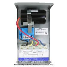
By Rendra Posted on July 9, 2020. May 22, 2020. Qd Control Box Wiring Diagram. - Allowed to be able to my own website, in this particular moment I'll provide you with concerning qd control box wiring diagram. . And today, this can be the very first picture: Franklin QD Control Box from qd control box wiring diagram , source:thepumpwarehouse ...
Franklin Electric Standard Control Box Description Franklin Electric Standard and Deluxe Boxes are for 3-wire, 1 to 15HP single-phase water systems that use standard/heavy-duty pressure switches, level switches or other pilot devices.
In the (really helpful) diagram it says that readings off of normal are suspect. Mine are very low: Franklin 1HP 230V Y-B 1.8 Ohm Y-R 2.7 Ohm (No ground faults) As was noted (and marked on the control box) "normal" is around 4 and 12, respectively. But other posts I've seen just say they should be "a few ohms"
Franklin Electric Pump Controller Model 2823 Wiring Diagram. Control Box Wiring Diagrams (Continued). 1 - hp (Date Codes 11C19 & Older). 1 - hp (Date Codes 11C19 & Newer). GB SubDrive75/00/50 Constant Pressure Controller Installation Manual Contents Controller Model Franklin Electric Motor Model Rated Power KW HP,5.
Franklin Electric Control Box Wiring Diagram. - Welcome in order to our weblog, on this time I'm going to show you in relation to franklin electric control box wiring diagram. . And today, this can be the very first image: Submersible Pump Control Box Wiring Diagram Image from franklin electric control box wiring diagram , source ...

Aim Manual Page 56 Single Phase Motors And Controls Motor Maintenance North America Water Franklin Electric
AIM Manual. Motor Maintenance » Single-Phase Motors and Controls (Page 54). Menu · << Page 53; Page 54; Page 55 >>. Control Box Wiring Diagrams ...

Franklin Electric Control Box Wiring Diagram Well Pump Pressure Switch Submersible Well Pump Well Pump
Control Box Wiring Diagrams. LINE POWER. FROM TWO POLE. FUSED SWITCH OR. CIRCUIT BREAKER,. AND OTHER CONTROL. IF USED. OVERLOAD. 275411114.
Diagram Mitsubishi M64 Wiring Full Version Hd Quality Diagramofbrain Andreapendibene It. Vmc Submersible Motor Control Model 14940951 V 230 S F Max Amp 10 4 Hp 1 59 99 Picclick. Franklin Electric 2801044915 Qd Submersible Motor Control Box 0 5 Hp 115v 1ph For 3 Wire Motors Fec2801044915. Aim Manual Page 55 Single Phase Motors And Controls Motor ...
Franklin Electric Well Pump Control Box Wiring Diagram- wiring diagram is a simplified standard pictorial representation of an electrical circuit.It shows the components of the circuit as simplified shapes, and the capability and signal connections with the devices.
Franklin Electric Franklin Electric 5800060100 Pumptec Plus Motor Protection Device 230v 1ph 1 2 5 Hp Fec58000601
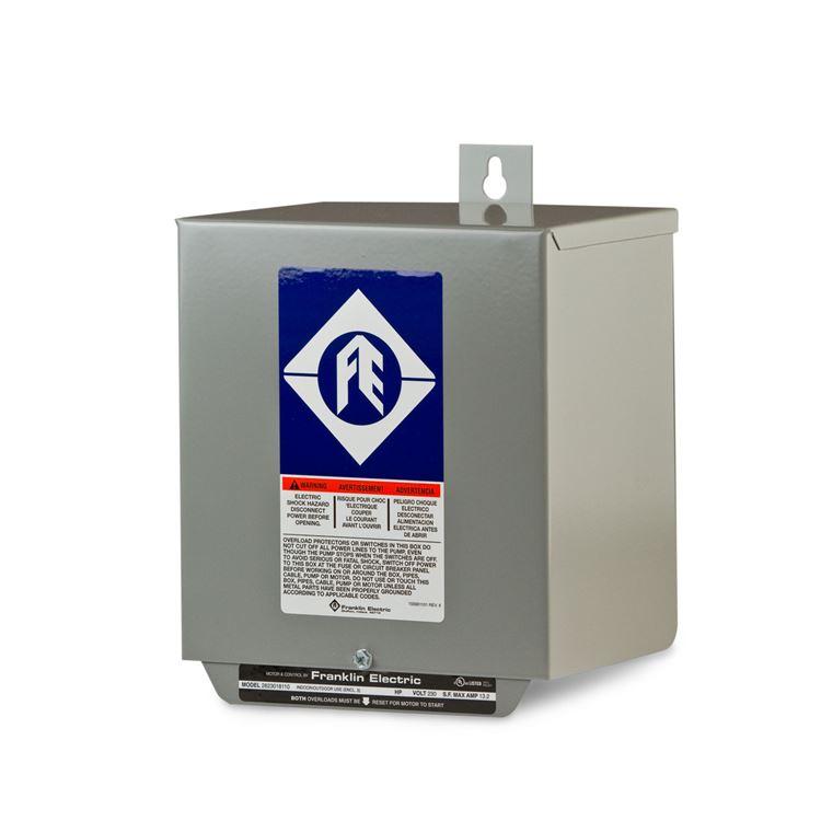
Franklin Electric Franklin Electric 2822019310 Deluxe Submersible Motor Control Box 7 5 Hp 230v 1ph For 3 Wire Motors Fec2822019310
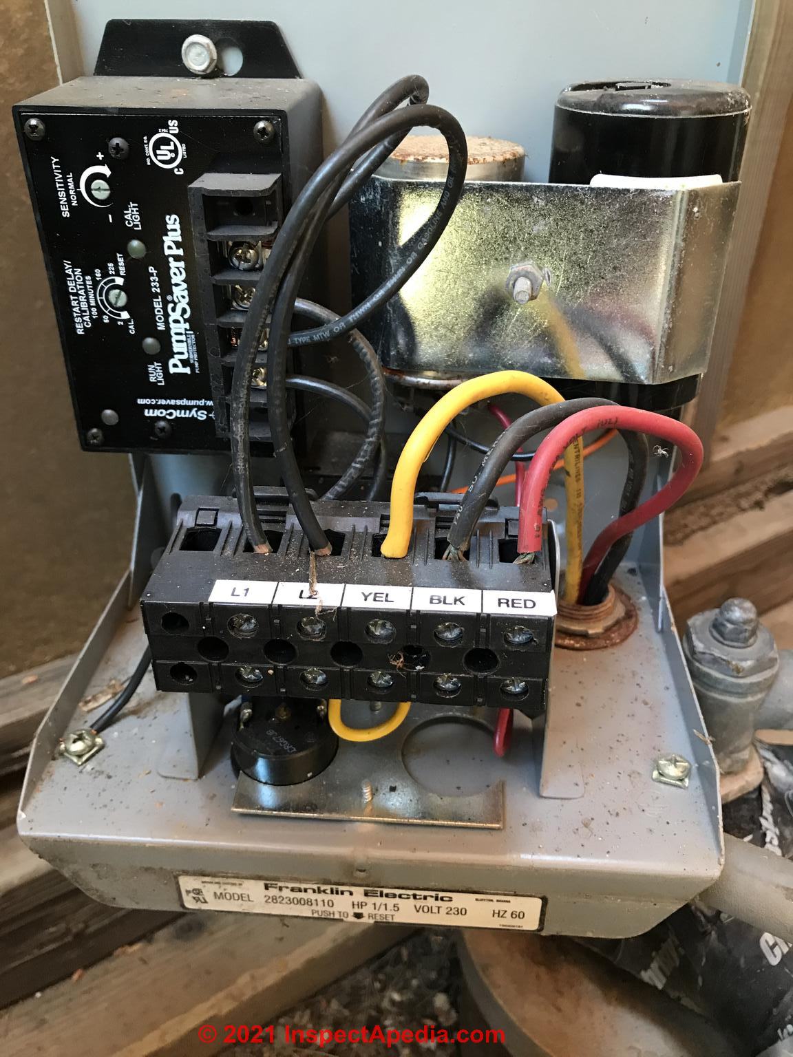
Water Pump Protection Switches Controls Prevent Pump Damage Or Pump Overheating Manual Automatic Switches Shut Off The Well Pump In Low Water Conditions

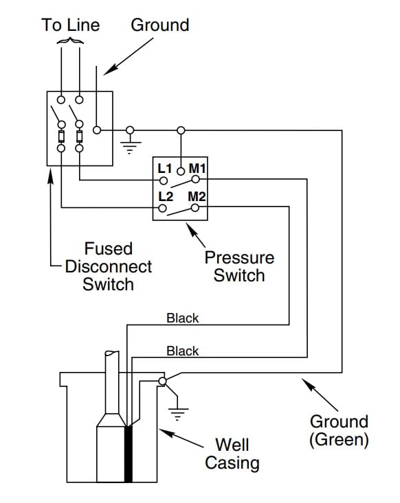
Wiring Diagram For 220 Volt Submersible Pump Bookingritzcarlton Info In 2021 Submersible Well Pump Jet Pump Well Pump
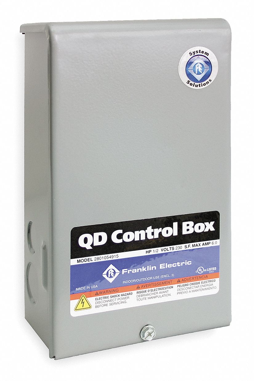
Franklin Electric Pump Control Panel 230v Ac Compatible Pump Type Submersible Deep Well No Switch Included 1lzv8 2801054915 Grainger






0 Response to "41 franklin electric control box wiring diagram"
Post a Comment