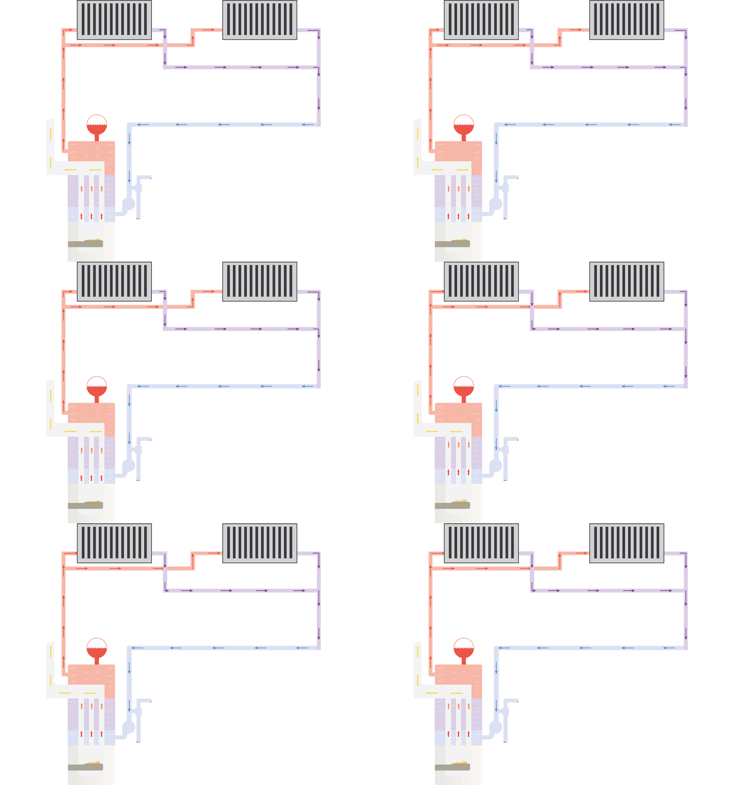
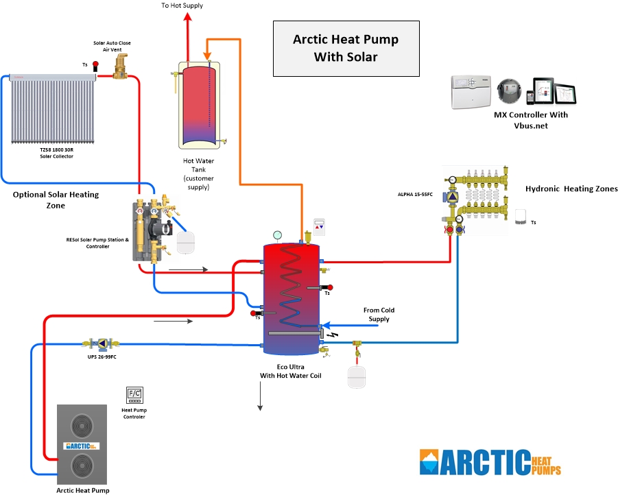
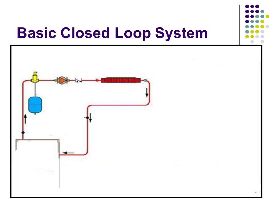
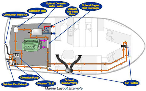
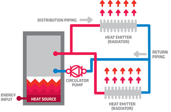
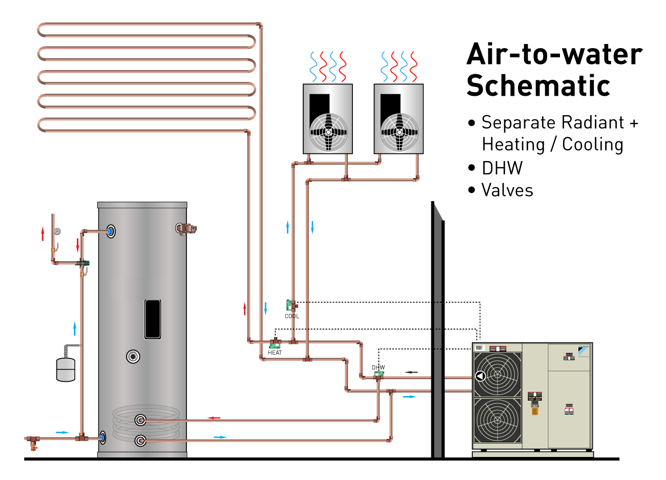
41 hydronic heating system diagram
A problem with this system is that it is not very flexible to changes, since changes can result in unbalanced pressure loss. [11] Figure 2. 3-pipe distribution system. [11] There are different categories of hydronic heating systems; there are low temperature systems and high temperature systems and there is low flow as well as high flow systems. Hydronic heating is the best choice for comfort and efficiency. Page 8. 8. Piping & Designing Hydronic Systems. This heat load ...80 pages
For hydronic systems that provide both heating and cooling, the distribution system may be configured as either a 2-pipe system or a 4-pipe system. A 2-pipe system is shown in Figure 3. Here, a single piping loop is used to supply either chilled water during the cooling season or hot water during the heating season.
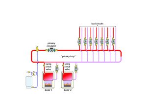
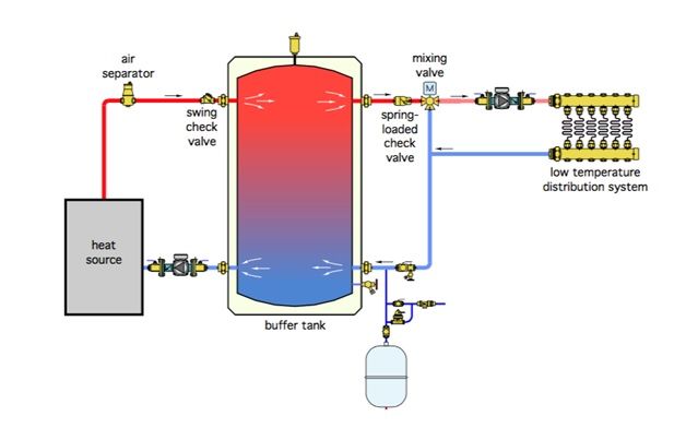
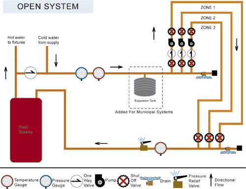
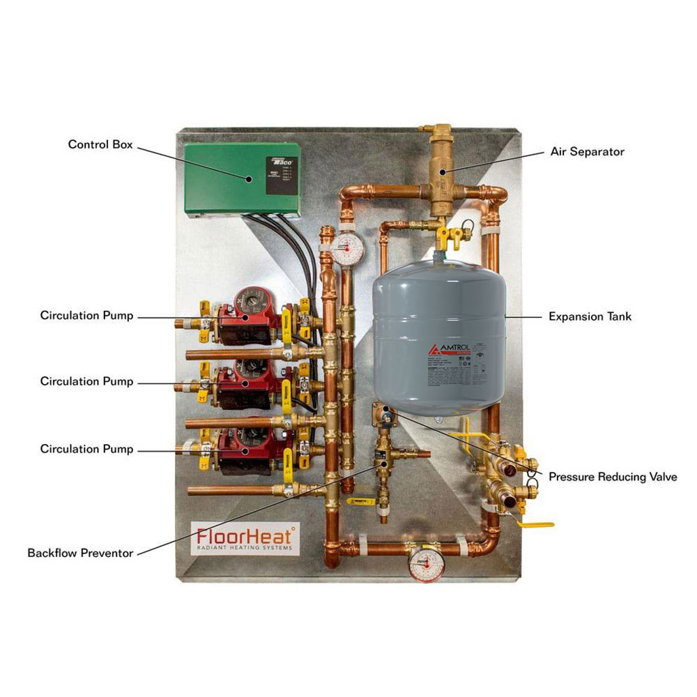
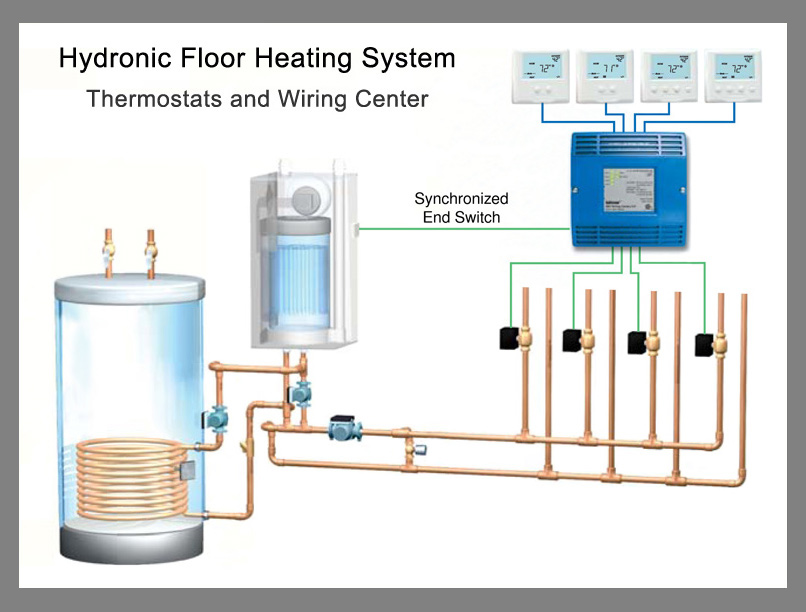
Hydronic heating system diagram
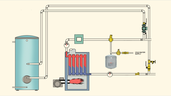
Boiler Piping Diagram For Radiant Heat. Installation Manuals – Our radiant heating installation manuals are written in easy to domestic water heater or boiler to make the hot water for radiant heat. Wiring diagrams for all controls, thermostats and temperature sensing devices. Radiant Heat Boiler Piping Diagram Pictures. How does a heating boiler work - what are the steps in its operating sequence? This article describes how a hot water heating system (hydronic heat) actually works, step by step, to heat a building. An understading of the sequence of steps in the operation of a heating system, from the moment that a thermostat calls for heat until the moment that the thermostat stops calling for heat can help ... The diagram below shows the general layout of an unvented hot water system: Instantaneous hot water heating systems This method involves using gas or electricity to heat the water to a useable temperature without the need to store the water. The electric versions use a coiled heating element to heat the water rapidly in a
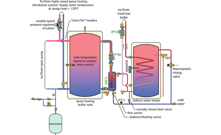
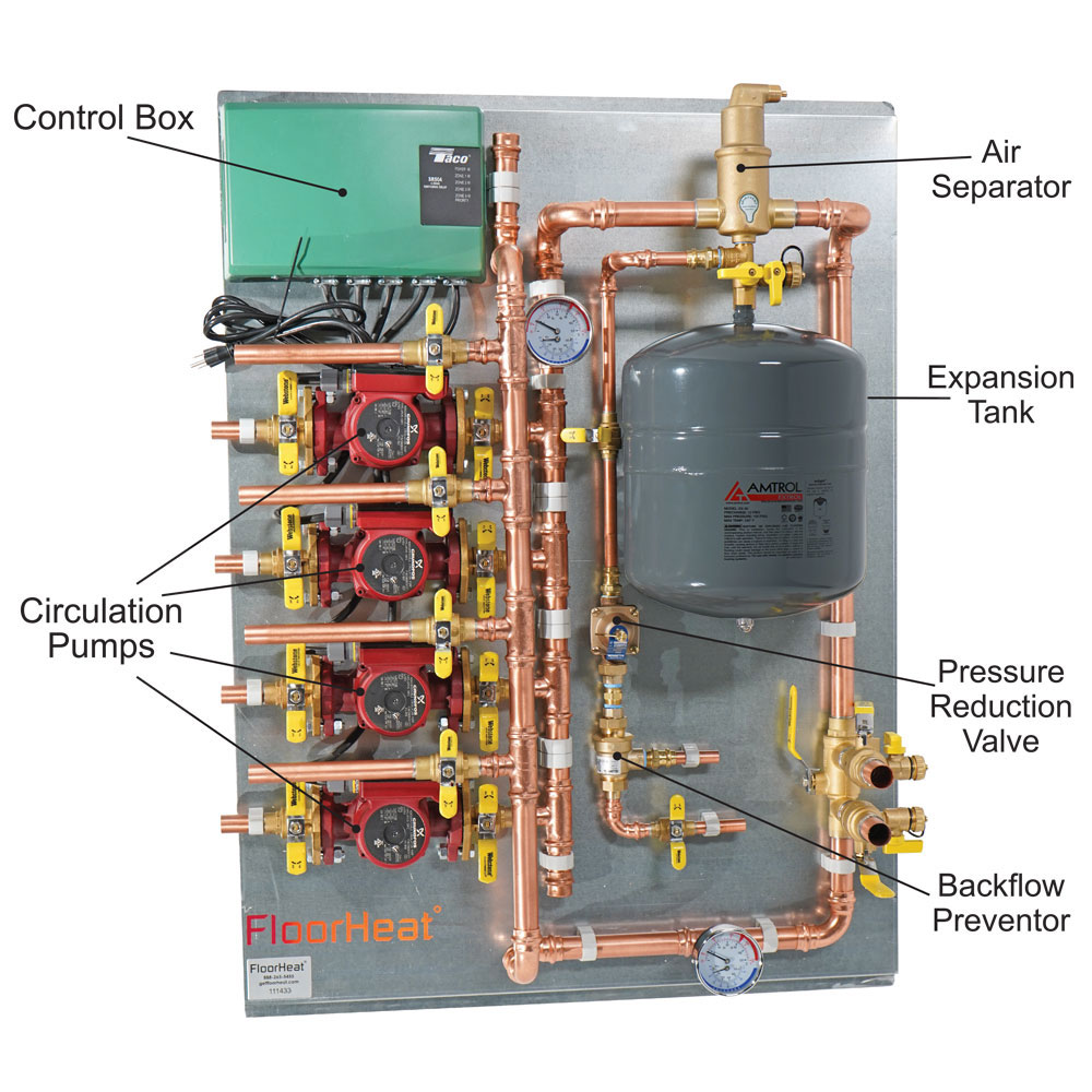
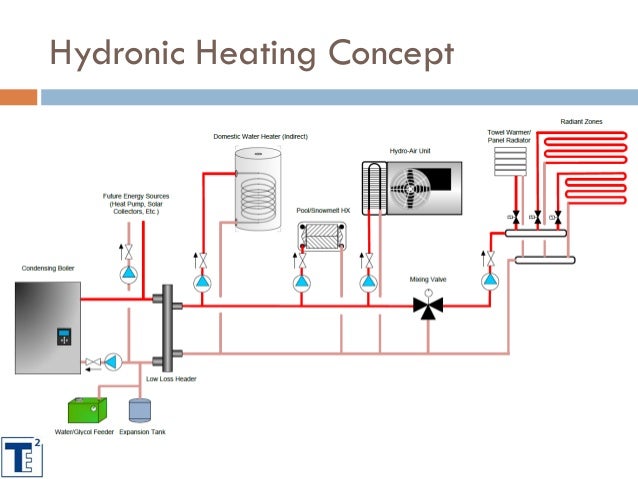
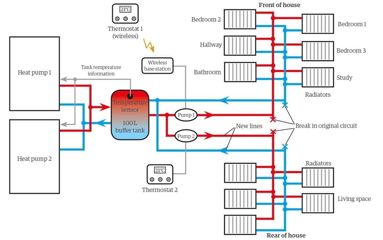
Hydronic heating system diagram. The most common type of hydronic distribution system in commercial buildings is known as a two-pipe, or parallel, system. In this design, which can also be used in residential systems, each heat emitter is located within a separate branch circuit that connects to a common supply main and common return main. Find out how it stacks up against hydronic heat technology when it comes to comfort, healthy indoor air quality, costs, and energy efficiency. You may be surprised. Hydronic Heating Suppliers and Specialists Finally, a short list of the top suppliers of hydronic heating equipment, boilers, and radiant heating specialists is provided. This payment is for release of electrical control interconnections drawings for hydronic heating system controls purchase from Modular Hydronics Shop and ...CA$4.50 · In stock 27 Apr 2017 — When a single supply water temperature is possible, consider zoning manifolds using zone valves or individual circuits using valve actuators.
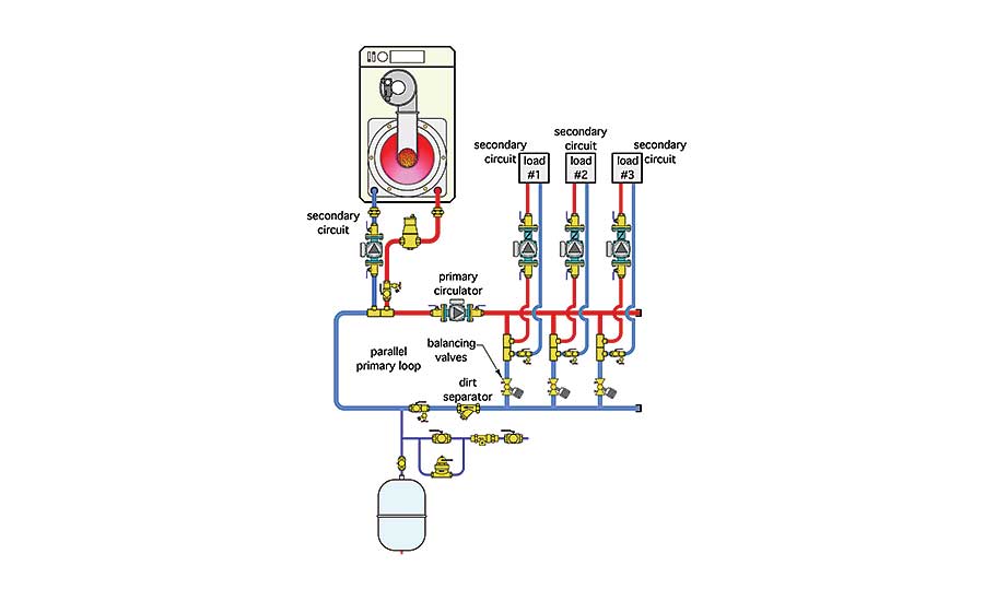
Hydronic Heating Boilers Description Series Piping Diagram PDF Piping Diagram DWG Genesis® One Boiler Primary, Secondary Hydronic Heating System GB 300 2500 ... Designing high performance hydronic heating systems involves a knowledge of ... Install zone valves on the supply side of zone circuits to block upward ... Download scientific diagram | 5: Schematic of a Hydronic Heating System [4] from publication: Modeling and control of hydronic building HVAC systems ... Combi system. This diagram illustrates how simple the heating system connected to a combi boiler is. No external pump, no tanks, no external expansion vessel, no motorised valves and in many cases item 6 is not needed either. (An automatic bypass valve is fitted inside most combi boilers by the manufacturer these days.)
Hydronic System Design Manual ©DECTRA CORPORATION - March 2013 8 FORCED AIR HEATING: DO NOT MOUNT A HOT WATER COIL ON THE RETURN SIDE OF THE FURNACE. Warm air will be flowing over the blower motor and may not provide sufficient motor cooling. Doing so will void the furnace warrantee and the UL listing of the furnace. This is why the best system designs include a heat exchanger to transfer heat from the domestic hot water to the space heating water, without the two kinds of water mixing. Plate-style exchangers work best in this application, though they do need to be descaled every 6 months to 2 years by running vinegar through the exchanger with a transfer pump. If that is true, there are some “insane” hydronic system designers in North ... The heat source(s) will inject heat into this loop, and the load circuits ... The diagram below shows the general layout of an unvented hot water system: Instantaneous hot water heating systems This method involves using gas or electricity to heat the water to a useable temperature without the need to store the water. The electric versions use a coiled heating element to heat the water rapidly in a
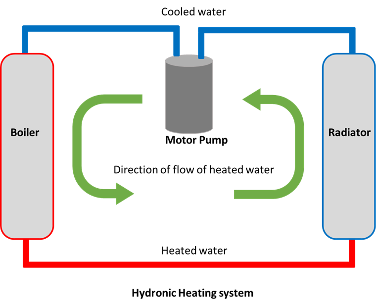
How does a heating boiler work - what are the steps in its operating sequence? This article describes how a hot water heating system (hydronic heat) actually works, step by step, to heat a building. An understading of the sequence of steps in the operation of a heating system, from the moment that a thermostat calls for heat until the moment that the thermostat stops calling for heat can help ...
Boiler Piping Diagram For Radiant Heat. Installation Manuals – Our radiant heating installation manuals are written in easy to domestic water heater or boiler to make the hot water for radiant heat. Wiring diagrams for all controls, thermostats and temperature sensing devices. Radiant Heat Boiler Piping Diagram Pictures.

Sprinter Van Hot Water Heater Hydronic Heating Systems Explained Van Build Tech Talk Series Ep 9 Youtube
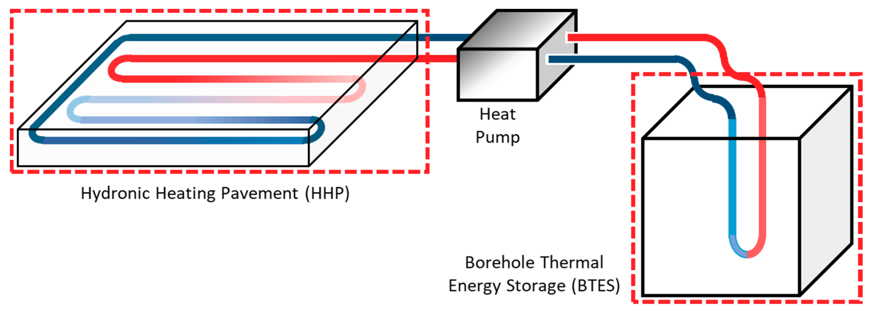
Energies Free Full Text Numerical Investigation Of Harvesting Solar Energy And Anti Icing Road Surfaces Using A Hydronic Heating Pavement And Borehole Thermal Energy Storage Html













0 Response to "41 hydronic heating system diagram"
Post a Comment