41 shear force and bending moment diagram problems and solutions pdf
02.07.2021 · Also draw the bending moment diagram for the arch. Fig. P6.2. Parabolic arch. 6.3 Determine the shear force, axial force, and bending moment at a point under the 80 kN load on the parabolic arch shown in Figure P6.3. Fig. P6.3. Parabolic arch. 6.4 In Figure P6.4, a cable supports loads at point B and C. Determine the sag at point C and the maximum tension in the cable. Fig. P6.4. … Bending Force Requirement Punch Workpiece T Die W Force T = Sheet Thickness W = Width of Die Opening L = Total length of bend (into the page) UTS = Ultimate Tensile Strength of material () 2 UTS W LT F= Note: the notation used in the text (L, W) differs from that used in the previous development (b, L).
Jasbir S. Arora, in Introduction to Optimum Design (Third Edition), 2012 Step 1: Project/Problem Description. A beam of rectangular cross-section is subjected to a bending moment M (N·m) and a maximum shear force V (N). The bending stress in the beam is calculated as σ=6M/bd 2 (Pa), and average shear stress is calculated as τ=3V/2bd (Pa), where b is the width and d is the depth of the …

Shear force and bending moment diagram problems and solutions pdf
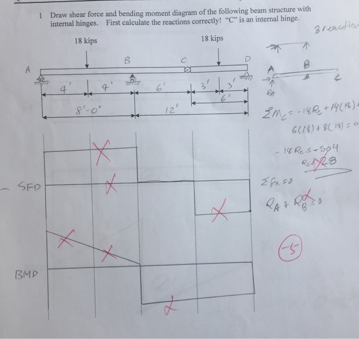
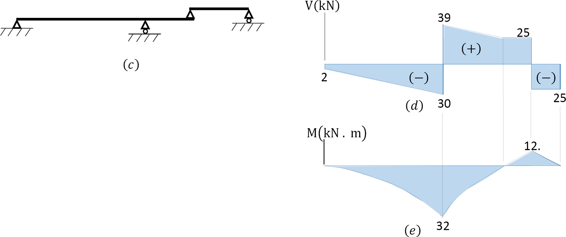
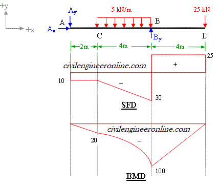
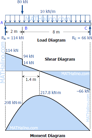
Calculate the shear force and bending moment for the beam subjected to the loads as shown in the figure, then draw the shear force diagram (SFD) and bending moment diagram (BMD). 2 kN/m 3 m A B EXAMPLE 7 18 Oct 2012 — Draw the shear force diagram and bending moment diagram for the beam. ... Solution: Consider a section (X – X') at a distance x from section ... 4.4 Area Method for Drawing Shear- Moment Diagrams Useful relationships between the loading, shear force, and bending moment can be derived from the equilibrium equations. These relationships enable us to plot the shear force diagram directly from the load diagram, and then construct the bending moment diagram from the shear force diagram.
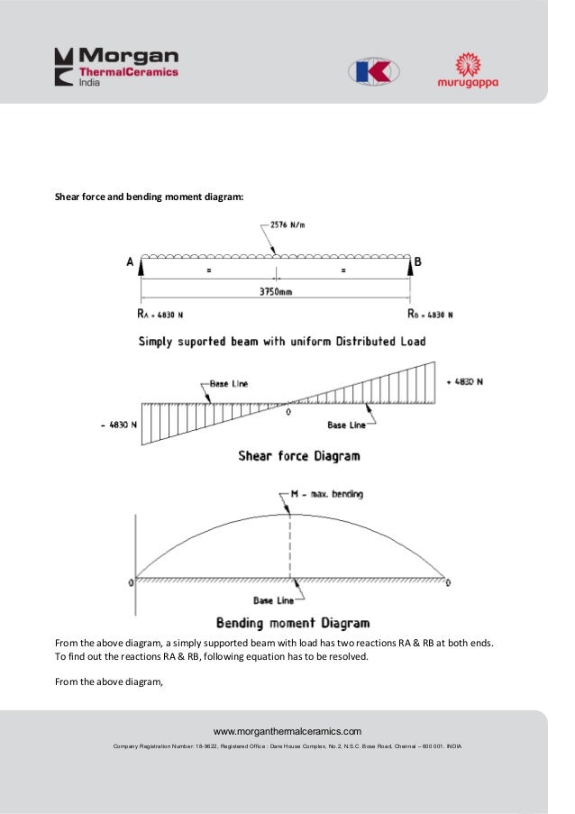
Shear force and bending moment diagram problems and solutions pdf. Complex Shear Force Diagram Practice Problems ... Shear Force and Bending Moment Diagrams . 9-2 Making a Shear Force Diagram _____ To determine the point where the supported truss is most prone to breakage, we use a shear force diagram to analyze the beam. The diagram starts at the zero point on both the left and ... bending moment. - Draw the shear force and bending moment diagrams ... EXAMPLE 2 – Solution ... Positive bending moment diagram drawn BELOW the beam. SHEAR ...77 pages Problem 9: Bending Moment and Shear force A constant load of ω0 per unit length is applied on a simply supported beam as shown below. Draw the shear force and bending moment diagram by a. Method of sections b. Integration method Solution: Formulas used: dv dm qV dx dx = = . We first find the support reactions which are necessary for both the ... 3m 266 CHAPTER 4 Shear Forces and Bending Moments Solution 4.3-12 Beam with ... 269 Shear-Force and Bending-Moment Diagrams When solving the problems for ...
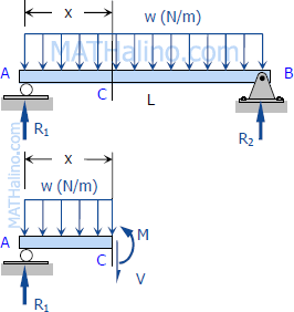
Download PDF. Download Full PDF Package. This paper. A short summary of this paper. 16 Full PDFs related to this paper. Read Paper. Calculations Handbook Of Civil Engineering. Download ... CE 331, Fall 2007 Shear & Moment Diagrams Examples 2 / 7 2. Draw the shear and moment diagram due to dead load. Note the magnitude and location of the maximum bending moment, MD. 3. Calculate the moment due to live load, ML. We will assume that the maximum moment due to dead plus live loads (MD+L) occurs at the location of the maximum moment ... The two expressions above give the value of the internal shear force and bending moment in the beam, between the distances of the 10 ft. and 20 ft. A useful way to visualize this information is to make Shear Force and Bending Moment Diagrams - which are really the graphs of the shear force and bending moment expressions over the length of the beam. 23.08.2021 · Shearing force and bending moment diagram. To determine the magnitudes of the shearing force and the bending moment and draw their diagrams, apply the obtained redundant to the primary beam, as shown in Figure 10.4e. The shearing force and the bending moment diagrams are shown in Figure 10.4h and Figure 10.4i.
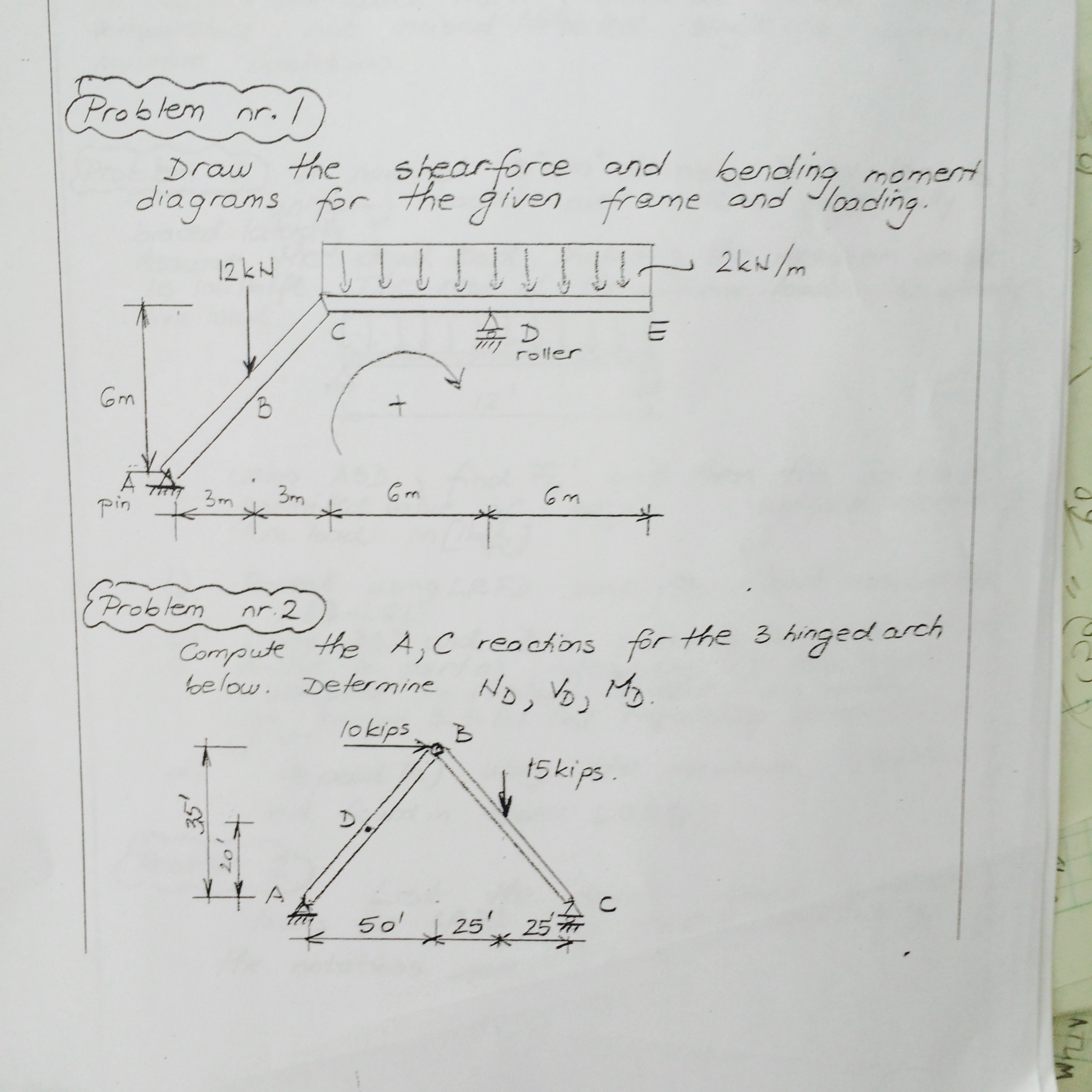
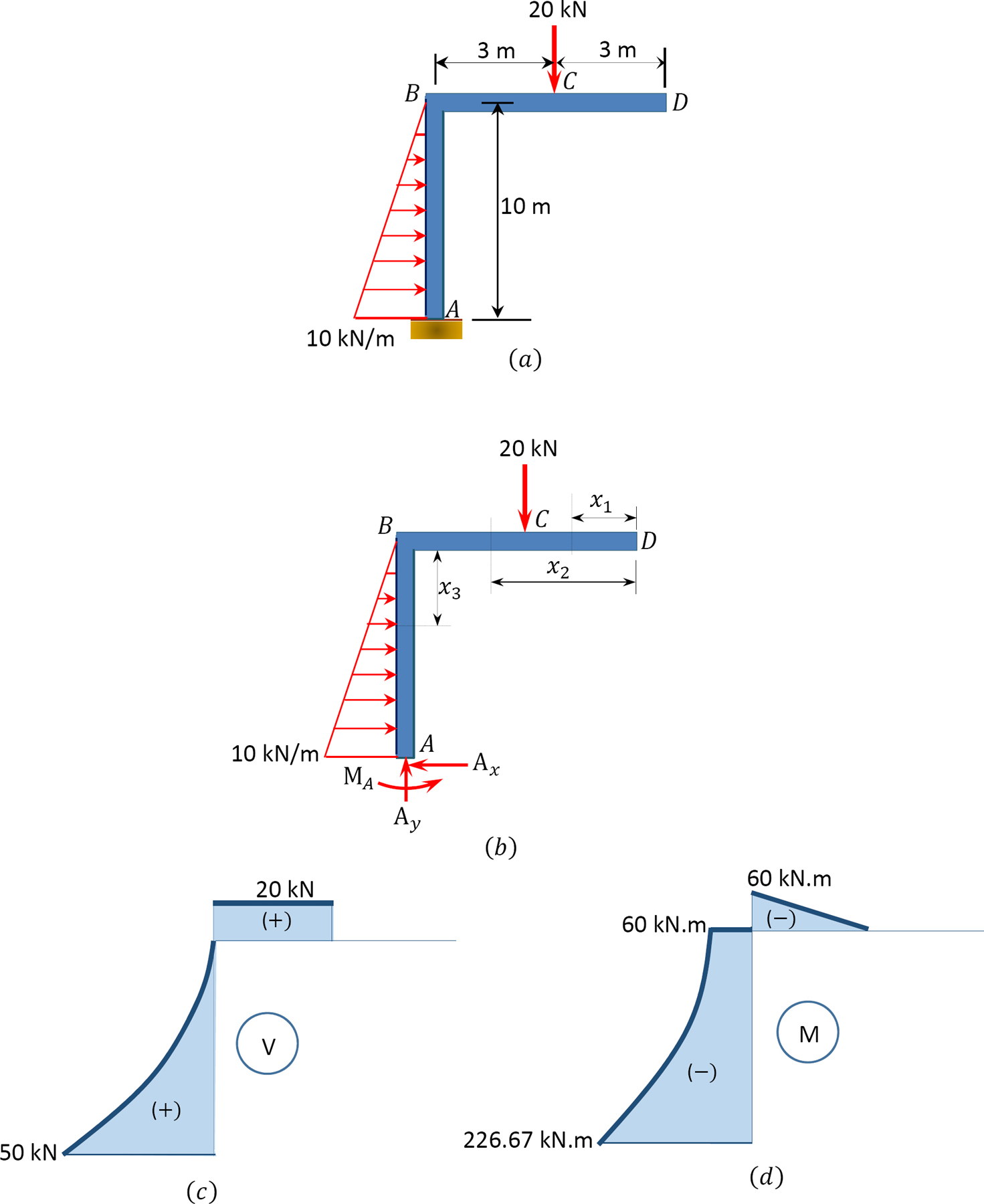
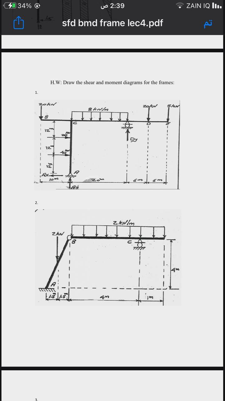
Problem 4.3-3 Determine the shear force V and bending moment M at the midpoint of the beam with overhangs (see figure). Note that one load acts downward and the other upward. Solution 4.3-3 Beam with overhangs 260 CHAPTER 4 Shear Forces and Bending Moments P P b L b P ¢1 2b L ≤ (upward) R A 1 L [P(L b b)] ©M B 0 Free-body diagram(C is the ... Axial Force, Shear Force and Bending Moment Diagrams for Plane Frames Previous definitions developed for shear forces and bending moments are valid for both beam and frame structures. However, application of these definitions, developed for a horizontal beam, to a frame structure will require some adjustments. 01.03.2013 · A load-moment interaction diagram, as shown in Fig. 2, is constructed for each column in a frame. If the combination of the axial load and the bending moment on a column fall inside the load-moment interaction diagram, the capacity of the designed column is adequate. If not, then the column does not have adequate strength and is penalized. Shear force and bending moment diagram problems and solutions pdf Shear Force Diagram is the Graphical representation of the variation of Shear Force Over the cross-section along the length of the beam. With the Shear Force Diagram’s help, we can identify Critical sections Subjected to Shear and design amendments to be made to avoid failure.
Strength Of Material (SOM) Notes Free Pdf Download Strength Of material Notes by Prof. M. S. Sivakumar, Indian Institute of Technology Madras. This notes
Module -4. Shear Force and Bending Moment Diagrams. Syllabus. Introduction, Types of beams, loads and reactions, shear forces and bending moments, rate of.12 pages
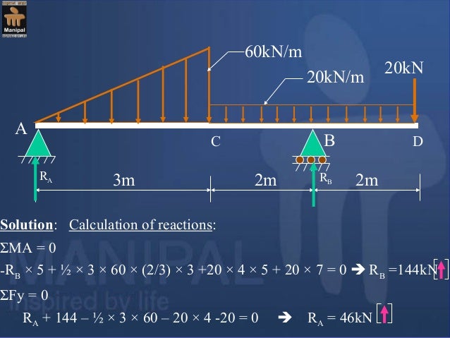
PDF_C8_b (Shear Forces and Bending Moments in Beams) Q6: A simply supported beam with a triangularly distributed downward load is shown in Fig. Calculate reaction; draw shear force diagram; find location of V=0; calculate maximum moment, and draw the moment diagram. 6k/ft 9 ft RA = (27k)(9-6)/9= 9k A B F = (0.5x6x9) = 27k x = (2/3)(9) = 6 ft
4.4 Area Method for Drawing Shear- Moment Diagrams Useful relationships between the loading, shear force, and bending moment can be derived from the equilibrium equations. These relationships enable us to plot the shear force diagram directly from the load diagram, and then construct the bending moment diagram from the shear force diagram.
18 Oct 2012 — Draw the shear force diagram and bending moment diagram for the beam. ... Solution: Consider a section (X – X') at a distance x from section ...
Calculate the shear force and bending moment for the beam subjected to the loads as shown in the figure, then draw the shear force diagram (SFD) and bending moment diagram (BMD). 2 kN/m 3 m A B EXAMPLE 7

Pdf Assessment Of Interactive Courseware For Shear Force And Bending Moment Diagrams Semantic Scholar

Pdf Chapter 5 Bending Moments And Shear Force Diagrams For Beams 5 0 Shear Force And Bending Moments Diagrams For Beams Petrus Guntur Supradana Academia Edu

Pdf Developing Graphical User Interface For Analysis Of Beam By Using Matlab Software Esat Journals Academia Edu












0 Response to "41 shear force and bending moment diagram problems and solutions pdf"
Post a Comment