42 aerator timer wiring diagram
Livewell Timer. We are one of the largest, fully integrated Livewell timer manufacturer in North America and have been servicing our customers for over 50-years. We are one of the largest supplier for Livewell timer for Marine industries and we manufacture this Timer in our Dallas, Texas facility and we provide one year warranty for all the Livewell timers. Big Foot Livewell Aerator Timer. I ask because I could wire up one timer to be used on all 4 aerators. I used 2 aerator motors in my diagram. The fuses for the aerators are shown in the diagram where they are currently installed inline in my 92 Skeeter. I don't think I need the diodes in there, but drew them on the schematic anyway.
aerator or water circulator is plugged into a GFI protected circuit. • 3 phase aerators (2.3, 3.3, 5.3) require a startup test after wiring to ensure proper rotation of the propeller. If the propeller is rotating in the op-posite direction, the unit will not perform properly and internal damage to the unit may occur. (See 3 phase startup ...
Aerator timer wiring diagram
Oct 14, 2013 · Oct 14, 2013. #3. Re: TH Automatic Aerator Control - Wiring Diagram??? Thanks for the diagram, but the TH controller has only three contacts on the timer, plus the three contacts on the rocker switch. One of the contacts on the timer is ground, leaving only two positive contacts. Problem is in finding out where these two positive contacts connect. Timer, 230 Volt Commercial STARTING AT: $195.00. This industrial-rated outdoor timer is perfect for our 230-volt fountains and aerators. Manufactured by Intermatic, this heavy-duty timer is designed to save energy while extending the life of your Scott Aerator product. RED ALERT AERATION TIMERS Features Red Alert™ aeration timers are designed for both indoor and outdoor use. Red Alert timers are a superior choice for time control on most aerator types including shaft-style, submersible, compressor or blower aerators, and for any application that requires mini-breaker (7 amp) capability.
Aerator timer wiring diagram. The above circuit diagram is for the 1-minute timer circuit. For 5 min, 10 min and 15 min you just have to change the resistor value (R 1). 1 Minute Timer Circuit: We have to configure 555 Timer in Mono-Stable mode to build a timer. The 555 Timer starts timing when switched ON. After one minute of time duration, the LED will automatically turn ON. The standard Power Control Center includes a fiberglass NEMA 4X enclosure with twenty-four hour timer control in the auto setting or manual control of the aerator unit, the required motor short circuit, ground fault and overcurrent protection, surge protection, and personnel GFCI protection (except 460V 60Hz. applications). Grasslin 24 Hour timer with 15 minute intervals. 16A Max, 120VAC These timers are commonly used in Aerobic System Control Panels. Out of Stock $53.00 MSRP: $79.00 The Extreme series is the upper left diagram. wiring diagram included. boat aerator livewell timer, 30 seconds x 3 minutes, 10 amp model lws-m. $ buy it now. or best offer. free shipping. 10 amp output.
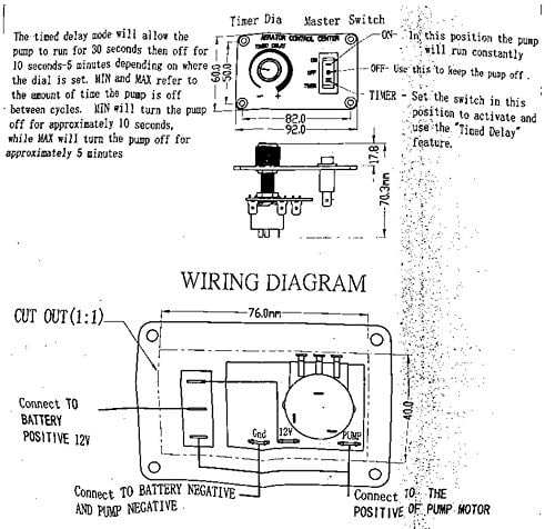
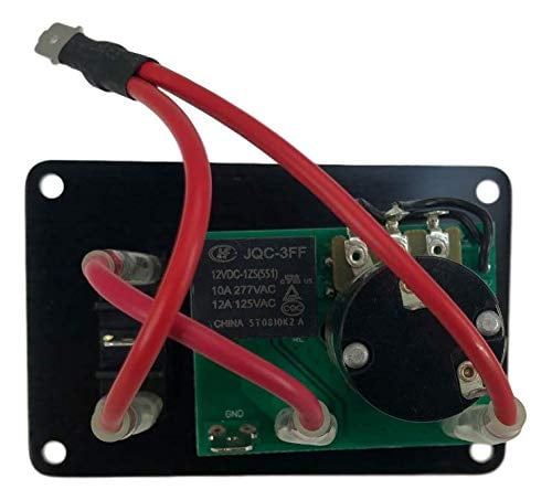
HOOK UP DIAGRAM Installation Select a location for mounting the Control Panel, cut a hole 1-7/8” x 1-5/8” (see sheet 2), secure panel with #8 sheet metal screws. After mounting panel, string wire to battery and pump areas. The RED wire connects to the Battery (+) positive, the BLACK wire connects to the Pump (-) Tracker aerator problem. I have a 2005 tracker and the aerator quit working. The pump works when hooked up to the battery. So the problem is in the switch or the timer. It looks like both the manual and the auto go through the timer. Any idea where I can find a wiring diagram? Palestine, Illinois, USA. This industrial-rated outdoor timer is perfect for our 230-volt fountains and aerators. Manufactured by Intermatic, this heavy-duty timer is designed to save energy while extending the life of your Scott Aerator product. Its clock motors are self-lubricating, and its manual on/off override switch won't alter your program. An easy-to-follow wiring diagram and easy-set design makes this a ... LIVEWELL TIMER INSTALLATION INSTRUCTIONS. INSTALLATION TOOLS. PUMPS. LEAVE THE PLASTIC CONNECTOR COVER IN PLACE ( black square in middle of timer ) To connect your adjustable livewell timer into your current boat you will need to buy some 16 gauge wire, I recommend buying 3 different colors. One for power (red), one for ground (black), and one for the pump (brown).
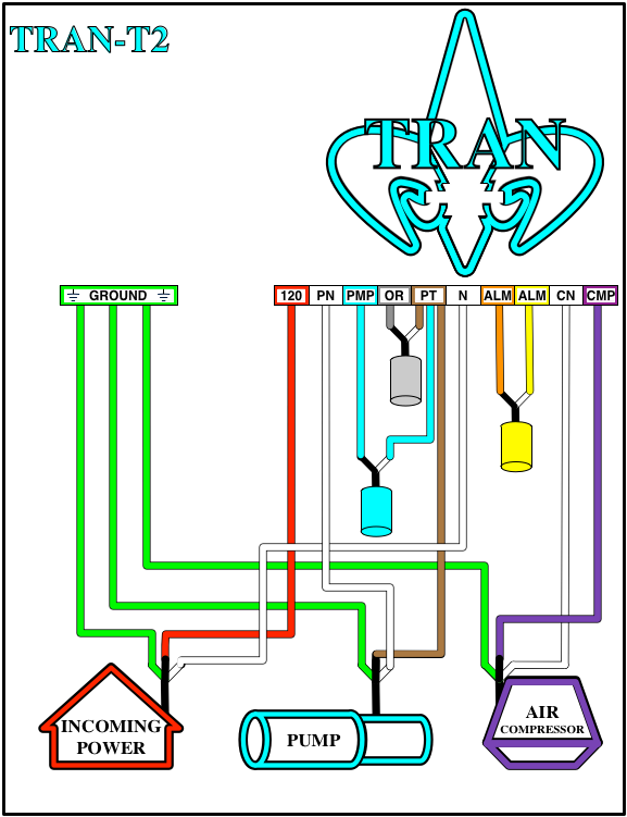
[DIAGRAM] Jet Aerator Motor Wiring Diagram pdf Download. November 11, 2021 Author: XAGC. [DIAGRAM] Jet Aerator Motor Wiring Diagram pdf Download Aerator provides complete treatment Our exclusive aerator infuses the fresh air that safe, living micro-organisms require to fully digest and treat wastewater inside the Aeration Chamber. Powered by our 1725 RPM, 115 volt, fractional horsepower motor, our quiet, reliable aerator is inexpensive to aerator or water circulator is plugged into a GFI protected circuit. • 3 phase aerators (2.3, 3.3, 5.3) require a startup test after wiring to ensure proper rotation of the propeller. If the propeller is rotating in the op-posite direction, the unit will not perform properly and internal damage to the unit may occur. (See 3 phase startup ... 1. Repair or replace aerator 2 to 10 years 2. Clean filters on aerator 6 mos. to 2 years 3. Break up scum in clarifier 6 mos. to 2 years 4. Pump sludge from aeration tank 2 to 5 years* 5. Pump sludge from pretreatment tank 2 to 5 years* 6. Check aeration diffusers annually 7. Check surge control weir 6 mos. 8. Repair or replace effluent pump 2 ...
Its components and wiring are protected within a lockable, corrosion resistant, ultraviolet-stabilized thermoplastic enclosure with removable flanges. Control Panels 180 -194 Audible Alerts Optional Warning Light Optional Timer* Terminal Strip Aerator Warning Light Circuit Breaker Control Switch Model # Part # Standard Features 180-194 Control ...
Simple wiring diagram included. Sealed case. 3 industrial grade terminals come with crimp-on wire connectors to resist corrosion and loosening. Water resistant, but for protected in-dash installation. Threaded brass shaft fits panels up to 5/8" 4" x 1" x 1.75", including knob. Drill one 3/8" hole. Requires 4" clearance behind panel.
Apr 16, 2019 · Livewell timer Installation Diagram, Installation Diagram, how to install livewell timer, how to wire a livewell timer, livewell timer wiring diagram. I need a generic wiring diagram for my aerator and recirc/pumpout switches. Both the bow and the console have illuminated on/off/on switches. Astronomical time clock wiring diagrams ranger ...
LiveWell Aerator Timer Configurable via Wi-Fi V1.0.3 LiveWell aerator timer operates the pump in cycling On-Off mode. The period duration can be set from 1 sec to 16 hours. The pump can be configured to run from 0 to 100 % duty cycle. For example, the timer can be set to operate at 80% duty for
Aerator connec-tion single phase aerators 2400VFX 110-120 5.6 12 C-25 plug in Plug into C-25 3400VFX 110-120 7.3 18 C-25 plug in Plug into C-25 3400HVFX 208-240 3.7 9 Hardwire C-85 plug into or hard-wire C85 4400VFX 110-120 11.3 40 C-25 plug in Plug into C-25 4400HVFX 208-240 5.7 20 Hardwire C-85 plug into or hard-wire C85 8400VFX 208-240 11 40 ...
MADE IN USA - Timer runs aerator pump 30 seconds every 3 minutes. Easy to use. 3 positions: Run Continuously; Run pump 30 seconds every 3 minutes; or Off. 12V, 10A. Can run 2 pumps. Simple wiring diagram and crimp-on wire connectors included Water resistant, but for protected in-dash installation. Threaded shaft fits panels up to 1/4"

Amazon Com Leisure Lectronics Variable Livewell Timer Aerator Pump 12v Switch For Boat Sports Outdoors
Keeps your Bait or Catch Alive & HealthyThis aerator control provides a source of oxygen-rich water to your live well automatically. This unit features a solid-state timer with adjustable off times to adjust to varying conditions. Easily adaptable to existing systems. Simply connect wiring according to instructions provided. Front panel is 3 1/4 x 3 1/4 and requires only 3"

Relays Business Office Industrial Digital Voltage Meter Test Time Delay 12v 24v Control Relay Timer Switch Module Suneducationgroup Com
A septic aerator is a fairly simple and easy piece to install in your septic system. The aerator is great to use for an older septic system because it helps to add and provide a great amount of oxygen to the septic system. Oxygen is a principal ingredient that helps to break down the waste that travels to and from your septic tank.
Aerator Timer and Alarm For Regenerative Blowers and Vane Pumps. Grasslin 24 HR Timer, 15 Minute Intervals. Item #: 80000-413-SB-JS. Our Price: $ 275.00 MSRP: $299.00 . View Product . Aerobic control panels are designed to control and monitor all of the functions of an aerobic septic system. These functions include supplying power to the air ...
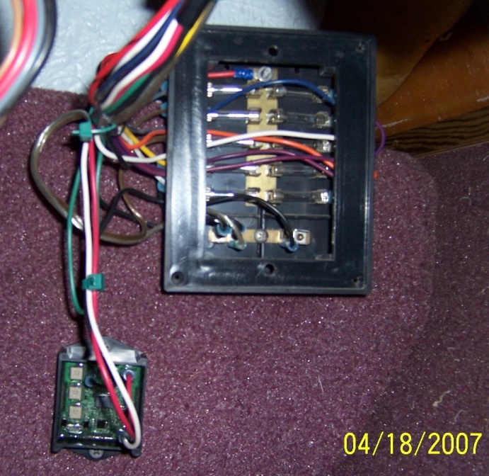
Re: Check my wiring schematic for Aerator timer Never mind. After finding a disconnected wire and examining the way the old timer was wired, I found that my diagram is the way they originally wired the boat, without the diodes. So that is the way I wired up the new timer. And the new timer has an off switch built in so it should be alright.
Feb 12, 2018 · This Livewell rocker switch is a Single Pole Single Throw ON-OFF switch. . A hard copy of the wiring diagram will be shipped with this switch. You can also find . 1 minute on 3 minutes off. it has an internal light on the switch. rocker,up is auto , rocke,r down is manual. middle position is off. on the back is.
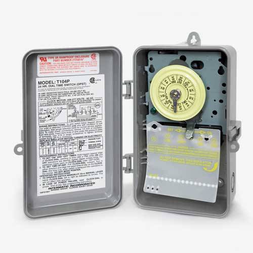
Scott Aerator Timer 230 Volt Mpn 20039 Best Prices On Everything For Ponds And Water Gardens Webb S Water Gardens
Electric technology
8400JF, 3.1JF, or 5.1JF Aerator 2.3JF, 3.3JF, or 5.3JF Aerator (Unit with cord or unit with Disconnect) (1) A1. Cord in separate box (1) (depending on size of cord) B. Float in separate box (1) (Diagram) 1. 3 Float Sections (1) 2. Top Float Bracket (3) 3. Bottom Float Bracket w/ 50' rope (3) 4. 9" x 3/8" Black Coated Bolt (6) 5. 3/8 ...
I need the wiring diagram for a 1995 stratos 201 XL Dual aerator switches on the bow - Answered by a verified Marine Mechanic We use cookies to give you the best possible experience on our website. By continuing to use this site you consent to the use of cookies on your device as described in our cookie policy unless you have disabled them.
This aerator control provides a source of oxygen-rich water to your live well automatically. This unit features a solid-state timer with adjustable off times to adjust to varying conditions. Easily adaptable to existing systems. Simply connect wiring according to instructions provided. Front panel is 3 1/4 x 3 1/4 and requires only 3" behind panel.
Control Box Wiring Diagram: control-box-wiring-diagram-2-3hp.pdf Scott Aerator's fountains, aerators, de-icers and Aquasweep products are proudly made and built right here in Holland, Michigan! 1-800-water-45 1-800-928-3745
Timer wiring
Jet aerator control panel. [SIZE=3] Hello, I have maintained my Jet Aerobic sytem for several years now. With the opproval of my Jet dealer I was given the OK to set my timer at the lowest run-time setting. In my case and on my timer this is 10/50. This allows the aerator motor to run for 10-minutes and rest for 50-minutes.
RED ALERT AERATION TIMERS Features Red Alert™ aeration timers are designed for both indoor and outdoor use. Red Alert timers are a superior choice for time control on most aerator types including shaft-style, submersible, compressor or blower aerators, and for any application that requires mini-breaker (7 amp) capability.

3 Position 12v Cycling Aerator Timer Livewell Marine Switch Pump Fish Boat Electrical Lighting Boat Parts Timer Aerator Boat Stuff
Timer, 230 Volt Commercial STARTING AT: $195.00. This industrial-rated outdoor timer is perfect for our 230-volt fountains and aerators. Manufactured by Intermatic, this heavy-duty timer is designed to save energy while extending the life of your Scott Aerator product.
Oct 14, 2013 · Oct 14, 2013. #3. Re: TH Automatic Aerator Control - Wiring Diagram??? Thanks for the diagram, but the TH controller has only three contacts on the timer, plus the three contacts on the rocker switch. One of the contacts on the timer is ground, leaving only two positive contacts. Problem is in finding out where these two positive contacts connect.

Ah3 Delay Timer And Relay Electrical Circuit Diagram Electrical Wiring Diagram Refrigeration And Air Conditioning

Buy Livewell Aerator Automatic Cycling Pump Timer With Variable Output Online In Indonesia B078qfhv2h

Leisure Lectronics Automatic Livewell Timer Aerator Pump 12v Module For Boat Buy Online In Guatemala At Desertcart 44668375
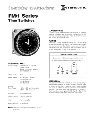
Intermatic Fm1stuzh 240u 21a 24 120 208 240v Analog Or Mechanical Timer Switch Installation Manual Manualzz

Amazon Com Leisure Lectronics Variable Livewell Timer Aerator Pump 12v Switch For Boat Sports Outdoors



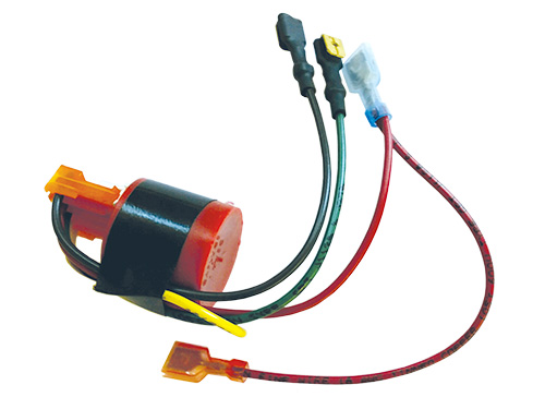





.gif)




0 Response to "42 aerator timer wiring diagram"
Post a Comment