42 draw shear force and bending moment diagram
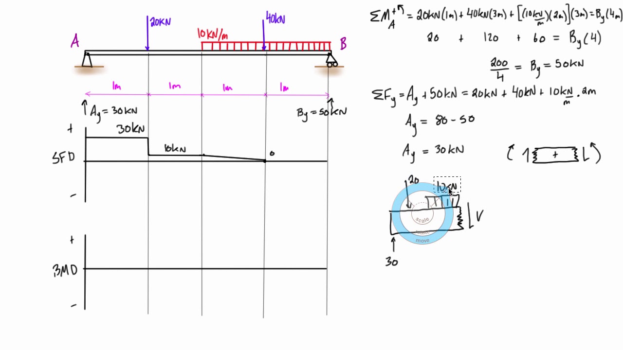
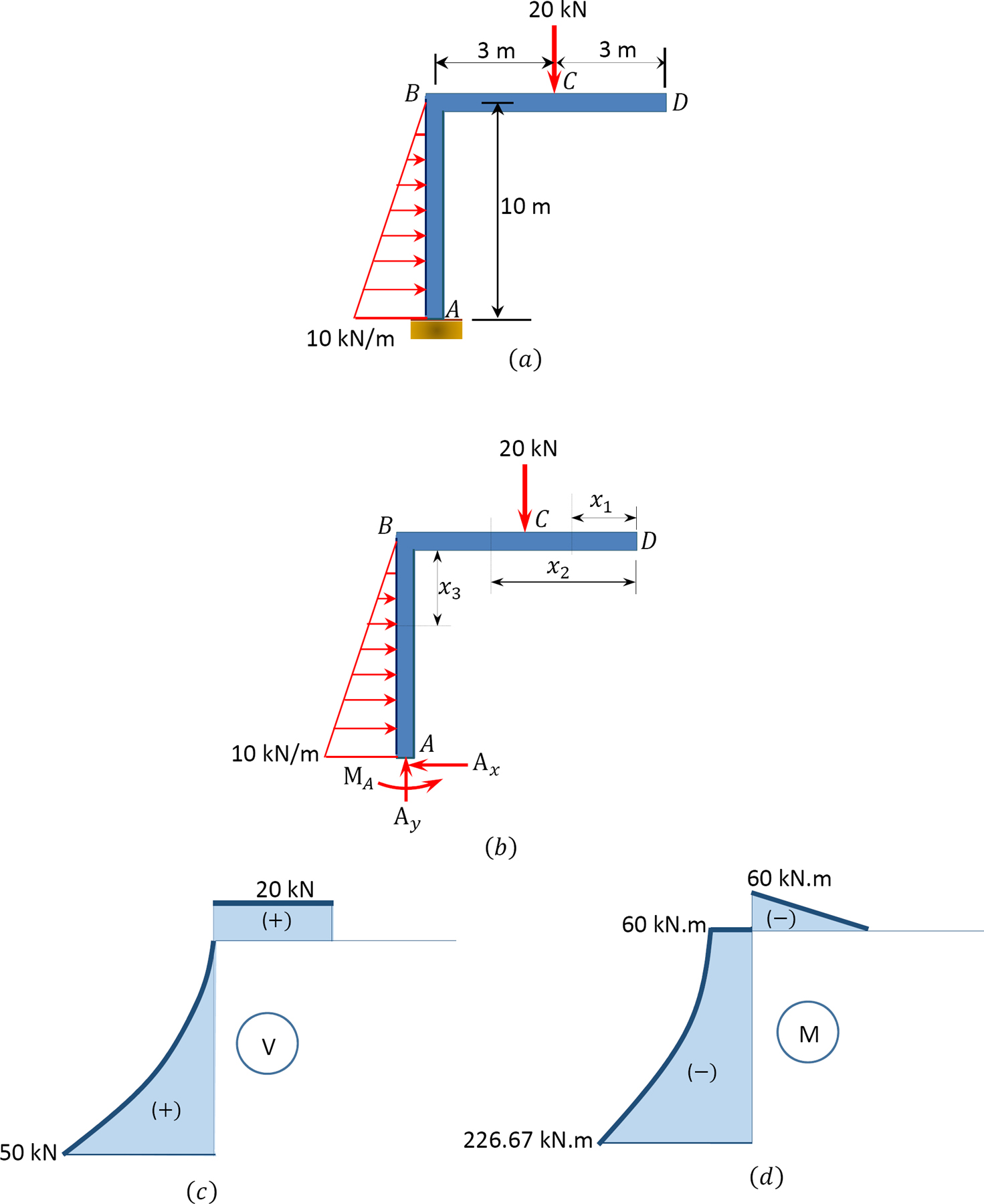
3.2 - Shear Force & Bending Moment Diagrams What if we sectioned the beam and exposed internal forces and moments. This exposes the internal Normal Force Shear Force Bending Moment ! What if we performed many section at ifferent values Of x, we will be able to plot the internal forces and bending moments, N(x), V(x), M(x) as a function Of position! 3. Start drawing shear force diagram from any of the extreme ends. Draw a vertical line of same length as the value of applied force at the point. If force acting on the point is downward then the vertical line should go downward or else upward. Suppose we are starting from point A. as force acting at point A in our case is 20 KN downward, so ...
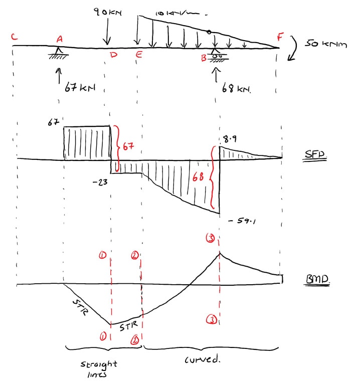
Steps to draw Shear force and Bending moment diagrams. In SFD and BMD diagrams Shear force or Bending moment represents the ordinates, and the Length of the beam represents the abscissa. Consider the left or the right portion of the section. Add the forces (including reactions) normal to the beam on the one of the portion.
Draw shear force and bending moment diagram
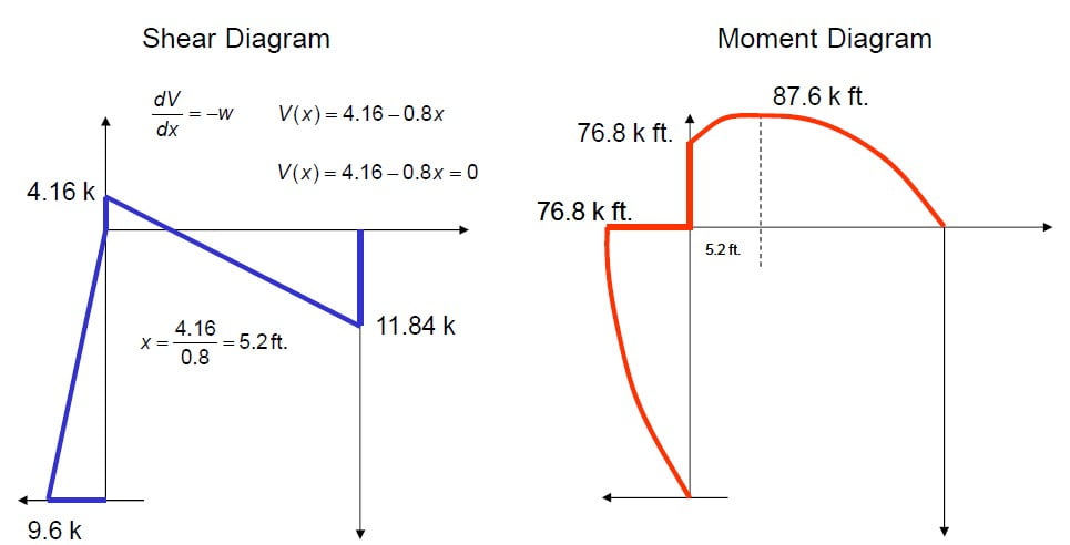
basics of shear force and bending moment diagrams and sign conventions for shear force and bending moment in our recent posts. We have also discussed the concept to draw shear force and bending moment diagrams for a cantilever beam with a point load during our previous posts. Draw the free body diagram for the beam. Step 2: Apply equilibrium equations. In X direction. ∑ FX = 0. ⇒ RAX = 0. In ...25 pages Now, let's draw the shear and moment diagram (remember to draw the diagram on the compression side of the member). Shear Diagram 9.6 k 4.16 k 11.84 k 5.2 ft. ... CIVL 3121 Shear Force and Bending Moment Diagrams for Frames 4/5. Shear and Moment Diagrams by Superposition Example: Draw the shear and moment diagrams for the ...
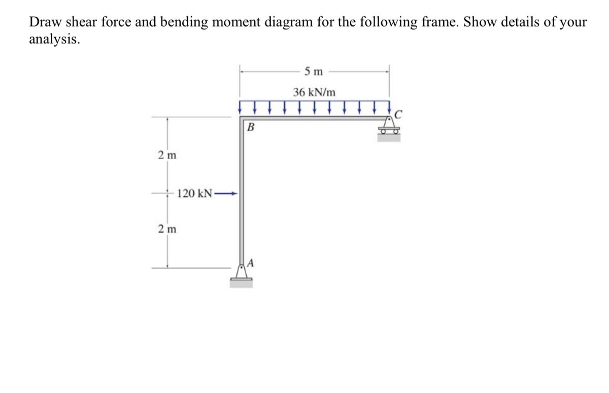
Draw shear force and bending moment diagram. Axial Force, Shear Force and Bending Moment Diagrams for Plane Frames Previous definitions developed for shear forces and bending moments are valid for both beam and frame structures. However, application of these definitions, developed for a horizontal beam, to a frame structure will require some adjustments. Shear and Moment Diagrams Calculate and draw the shear force and bending moment equations for the given structure. 11 Sketching the Deflected Shape of a Beam or Frame Qualitative Deflected Shape (elastic curve) ≡ a rough (usually exaggerated) sketch of the neutral surface of the structure in the deformed position under the action Drawing shear force and bending moment diagrams: The shear load and bending moment diagrams are constructed by integrating the distributed load to get the shear diagram (adding jumps at all point loads), and integrating the shear diagram to get the bending moment (adding jumps at all point couples). The following is an example of one shear load ... shear force and bending moment equations. And (2) draw the shear force and bending moment diagrams. Neglect the weight of the beam. Solution Note that the triangular load has been replaced by is resultant, which is the force 0.5 (12) (360) = 2160 lb (area under the loading diagram) acting at the centroid of the loading diagram.
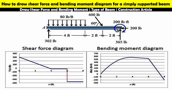
Being able to draw shear force diagrams (SFD) and bending moment diagrams (BMD) is a critical skill for any student studying statics, mechanics of materials, or structural engineering. There is a long way and a quick way to do them. You can just ignore point C when drawing the shear force diagram. When drawing the bending moment diagram you will need to work out the bending moment just before and just after point C: Just before: bending moment at C = 3·30 - 1·40 = 50Nm. Just after: bending moment at C = 3·30 - 1·40 - 20 = 30Nm. Calculate the shear force and bending moment for the beam subjected to an uniformly distributed load as shown in the figure, then draw the shear force diagram (SFD) and bending moment diagram (BMD). 5 kN/m 3 m A B EXAMPLE 6 The moment diagram will plot out the internal bending moment within a horizontal beam that is subjected to multiple forces and moments perpendicular to the length of the beam. For practical purposes, this diagram is often used in the same circumstances as the shear diagram, and generally both diagrams will be created for analysis in these ...
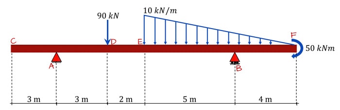
Determining shear forces and bending moments along the length of a beam typically involves three steps: 1- First we draw the free body diagram of our beam. 2- Next we use the equilibrium equations to calculate the reaction forces and moments. 3- Finally, we cut our beam at a single location and use the equilibrium equations to determine the ... The ability to draw shear force and bending moment diagrams on beam-like components is an important skill for mechanical engineering students. We found that some students had difficulty to draw effectively the shear force and bending moment diagrams during the course and even in their senior year. Answer (1 of 6): Drawing shear force and bending moment > How to find a Shear Force Diagram (SFD) of a Simple Beam In this tutorial, we will look at calculating the shear force diagram of a simple beam. A shearing force occurs when a perpendicular force is applied to static material (in this ca... Shear and Bending Moment Diagram Example A beam is supported by a pin support at point A and extends over a roller support at point D. The beam is and subjected to a linearly varying load from A to B, a point moment at point D a point load at point E as shown. Draw the diagram and the bending moment diagram for the beam. Label
Shear Force And Bending Moment Diagram Example 5 Mixed Distributed And Point Loads Youtube
PDF_C8_b (Shear Forces and Bending Moments in Beams) Q6: A simply supported beam with a triangularly distributed downward load is shown in Fig. Calculate reaction; draw shear force diagram; find location of V=0; calculate maximum moment, and draw the moment diagram. 6k/ft 9 ft RA = (27k)(9-6)/9= 9k A B F = (0.5x6x9) = 27k x = (2/3)(9) = 6 ft
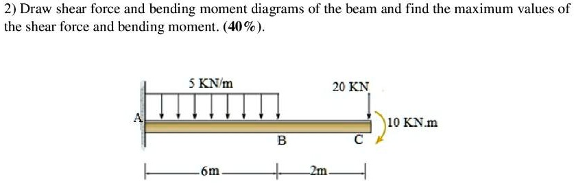
Solved 2 Draw Shear Force And Bending Moment Diagrams Of The Beam And Find The Maximum Values Of The Shear Force And Bending Moment 40 5 Knm 20 Kn 110 Knm 6m
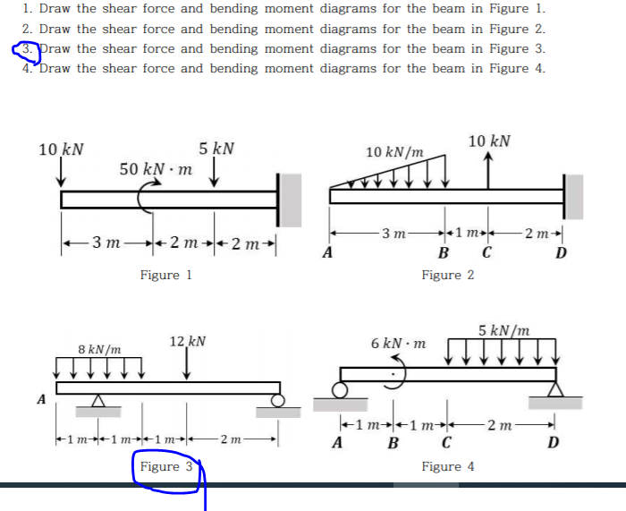
Step 2: Step 1: Knowing Forces Effect on Beams. - Knowing how different forces effect beams is important to be able to calculate the shear and bending moments. - A point force will cause a rectangular shear and a triangular bending moment. - A rectangular distributed load will cause a triangular shear and a quadratic bending moment.
Shear And Bending Moment Diagrams For Frames Construction How
Once you have the reactions, draw your Free Body Diagram and Shear Force Diagram underneath the beam. Finally calculating the moments can be done in the following steps: 2. From left to right, make "cuts" before and after each reaction/load. To calculate the bending moment of a beam, we must work in the same way we did for the Shear Force ...

Drawing Shear Force Bending Moment Diagram File Exchange Pick Of The Week Matlab Simulink
If we have bending moment diagram then just by differentiating the shear at each point w.r.t. distance gives shear force · If we have shear force diagram then by ...6 answers · Top answer: Drawing shear force and bending moment %3E How to find a Shear Force Diagram (SFD) of ...
Solved 1 Draw The Shear Force And Bending Moment Diagrams Chegg Com
Any changes made will automatically re-draw the free body diagram any simply supported or cantilever beam. The beam reaction calculator and Bending Moment Calculations will be run once the "Solve" button is hit and will automatically generate the Shear and Bending Moment Diagrams.
Answered Draw Shear Force And Bending Moment Bartleby
Chapter-4 Bending Moment and Shear Force Diagram S K Mondal's Shear force: At a section a distance x from free end consider the forces to the left, then (V x) = - P (for all values of x) negative in sign i.e. the shear force to the left of the x-section are in downward
Draw Shear Force And Bending Moment Type Of Beam Construction Video
Shear Force and Bending Moment Diagram for a simply supported beam are as follows. Case 01. Simply supported beam with point load. Simply supported beam with point load. To find out Shear Force, first we will calculate R a and R c. Beam is simply supported ∑M a = ∑M c = 0. Let us consider ∑M a = 0. 6*4 - R c *8 = 0 (Clockwise bending ...
The Ultimate Guide To Shear And Moment Diagrams Degreetutors Com
Shear and Moment Diagrams Consider a simple beam shown of length L that carries a uniform load of w (N/m) throughout its length and is held in equilibrium by reactions R1 and R2. Assume that the beam is cut at point C a distance of x from he left support and the portion of the beam to the right of C be removed. The portion removed must then be replaced by vertical shearing

Shear Force And Bending Moment Diagram For Simply Supported Beam
4- Write the equations of equilibrium for the resultant segment and solve for the shear force and bending moment at ,. Therefore, 5- Plot the functions and on x-y plots, with the x axis representing the distance from the left end of the beam, and the y axis representing the values of and .The plot gives a shear force diagram (SFD) and the plot gives a bending moment diagram (BMD).
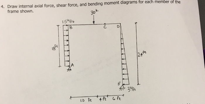
Solved Draw Internal Axial Force Shear Force And Bending Moment 1 Answer Transtutors
Module -4. Shear Force and Bending Moment Diagrams. Syllabus. Introduction, Types of beams, loads and reactions, shear forces and bending moments, rate of.12 pages
How To Draw Shear Force And Bending Moment Diagrams Strength Of Materials Quora
4.0 Building Shear and Moment Diagrams. In the last section we worked out how to evaluate the internal shear force and bending moment at a discrete location using imaginary cuts. But to draw a shear force and bending moment diagram, we need to know how these values change across the structure.

Shear Force And Bending Moment Diagrams Graphical Method Slide Share
Shear and bending moment diagrams are analytical tools used in conjunction with structural analysis to help perform structural design by determining the value of shear force and bending moment at a given point of a structural element such as a beam. These diagrams can be used to easily determine the type, size, and material of a member in a ...
Shear Force And Bending Moment Diagram For Simple Supported Beam
The shear force diagram and bending moment diagram can now be drawn by using the various values of shear force and bending moment. For bending moment diagram the bending moment is proportional to x, so it depends, linearly on x and the lines drawn are straight lines.
4 4 Relation Among Distributed Load Shearing Force And Bending Moment Engineering Libretexts
The code, given below, is created using Python and using Numpy and Matplotlib libraries. It can draw the bending moment diagram(BMD) and Shear Force Diagram(SFD) for a Simply Supported Beam (SSB) with a point load at any location on that beam. The solution code when run will ask for the following inputs:

Draw The Shear Force And Bending Moment Diagrams For The Beam Shown Below Study Com
Now, let's draw the shear and moment diagram (remember to draw the diagram on the compression side of the member). Shear Diagram 9.6 k 4.16 k 11.84 k 5.2 ft. ... CIVL 3121 Shear Force and Bending Moment Diagrams for Frames 4/5. Shear and Moment Diagrams by Superposition Example: Draw the shear and moment diagrams for the ...

Draw The Shear And Moment Diagrams For The Beam With Calculation
Draw the free body diagram for the beam. Step 2: Apply equilibrium equations. In X direction. ∑ FX = 0. ⇒ RAX = 0. In ...25 pages
Solved Draw A Shear Force And Bending Moment Diagrams 1 5 Chegg Com
basics of shear force and bending moment diagrams and sign conventions for shear force and bending moment in our recent posts. We have also discussed the concept to draw shear force and bending moment diagrams for a cantilever beam with a point load during our previous posts.
How To Draw The Bending Moment Diagrams Employing Displacement Methods Quora

Bending Moment Diagram An Overview Sciencedirect Topics

A Displacement Response B Bending Moment Diagram And C Shear Download Scientific Diagram

Bending Shear And Moment Diagram Graphical Method To Construct Shear Ppt Download

Drawing Bending Moment Diagrams Effectively Mechanicalbase
Web Ncyu Edu Tw

Drawing Bending Moment Diagrams Effectively Mechanicalbase

Shear And Moment Diagram Wikipedia
How To Draw Shear Force And Bending Moment Diagram In Case Of Cantilever Beam Daily Engineering

2 Group Solving Problem Draw The Shear Force And Bending Moment Diagrams For The Beam Shown U Homeworklib
Ecoursesonline Iasri Res In

Draw Shear Force And Bending Moment Diagram For Cantilever Beam Bending Moment Shear Force Mathematical Expression

Shear Force And Bending Moment Diagram For Overhanging Beam Mechanical Engineering Concepts And Principles

Learn How To Draw Shear Force And Bending Moment Diagrams Engineering Di Mechanical Engineering Design Mechanical Engineering Civil Engineering Construction
Calculate And Sketch The Bending Moment And Shearing Force Diagrams For The Horizontal Beam Shown In Figure Sarthaks Econnect Largest Online Education Community
The Ultimate Guide To Shear And Moment Diagrams Degreetutors Com
Shear Load And Bending Moment Diagrams

Learn How To Draw Shear Force And Bending Moment Diagrams Engineering Discoveries

Draw The Shear Force Diagram And Bending Moment Diagram For The Timber Beam Loaded As Shown In Fig
Bending Moment Shear Force Structural Analysis Aero 103
Shear Force And Bending Moment Diagram For Cantilever Beam Civilmint

Learn How To Draw Shear Force And Bending Moment Diagrams To Get Info Bending Moment Structural Analysis Learn Physics
Calculate And Sketch The Bending Moment And Shearing Force Diagrams For The Horizontal Beam Shown In Figure Sarthaks Econnect Largest Online Education Community

Draw The Shear Force And Bending Moment Adapala S Forum
Solved Draw The Shear Force And Bending Moment Diagram Of The Beam Show 1 Answer Transtutors
0 Response to "42 draw shear force and bending moment diagram"
Post a Comment