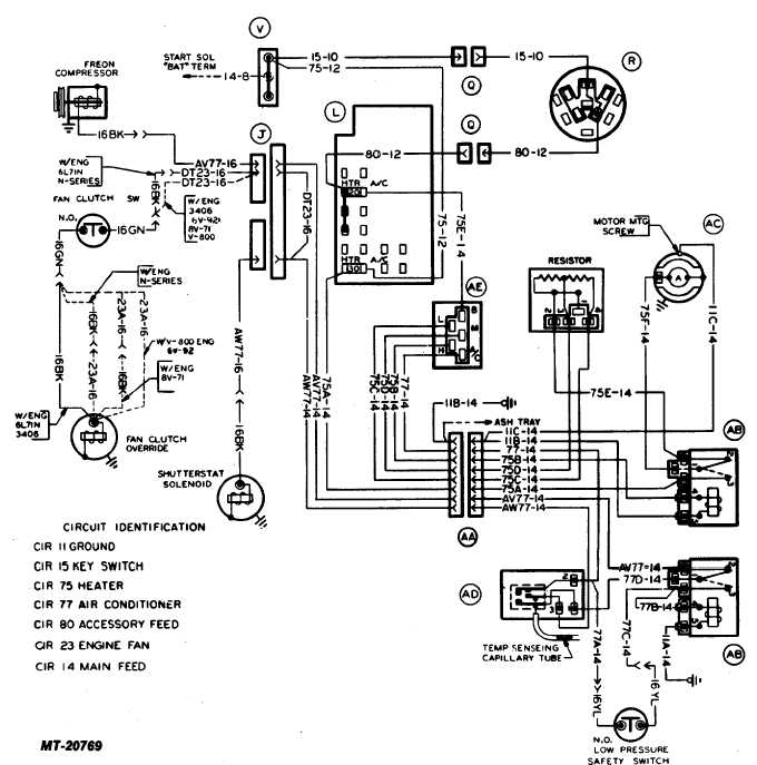
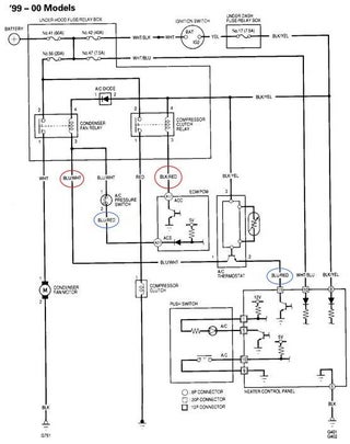
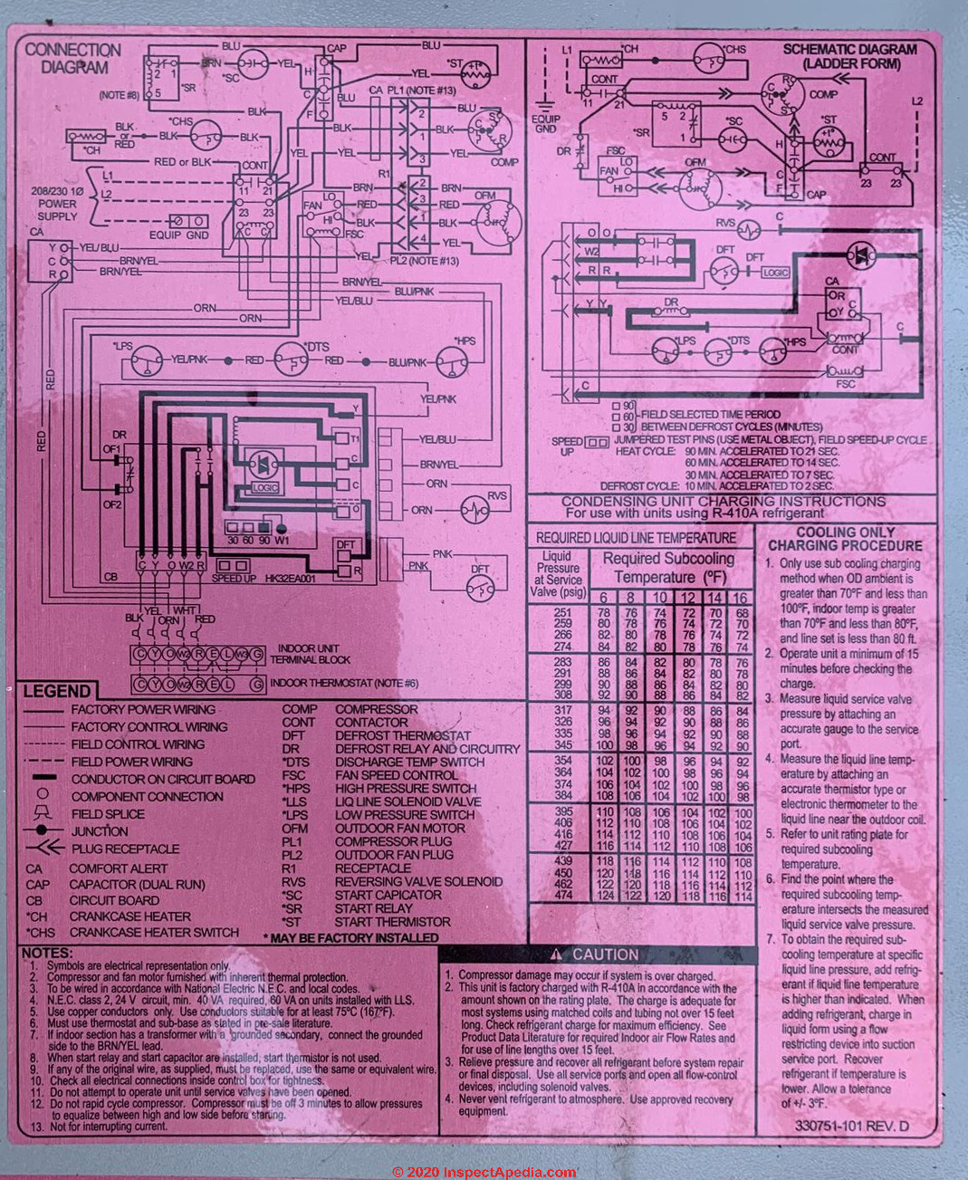
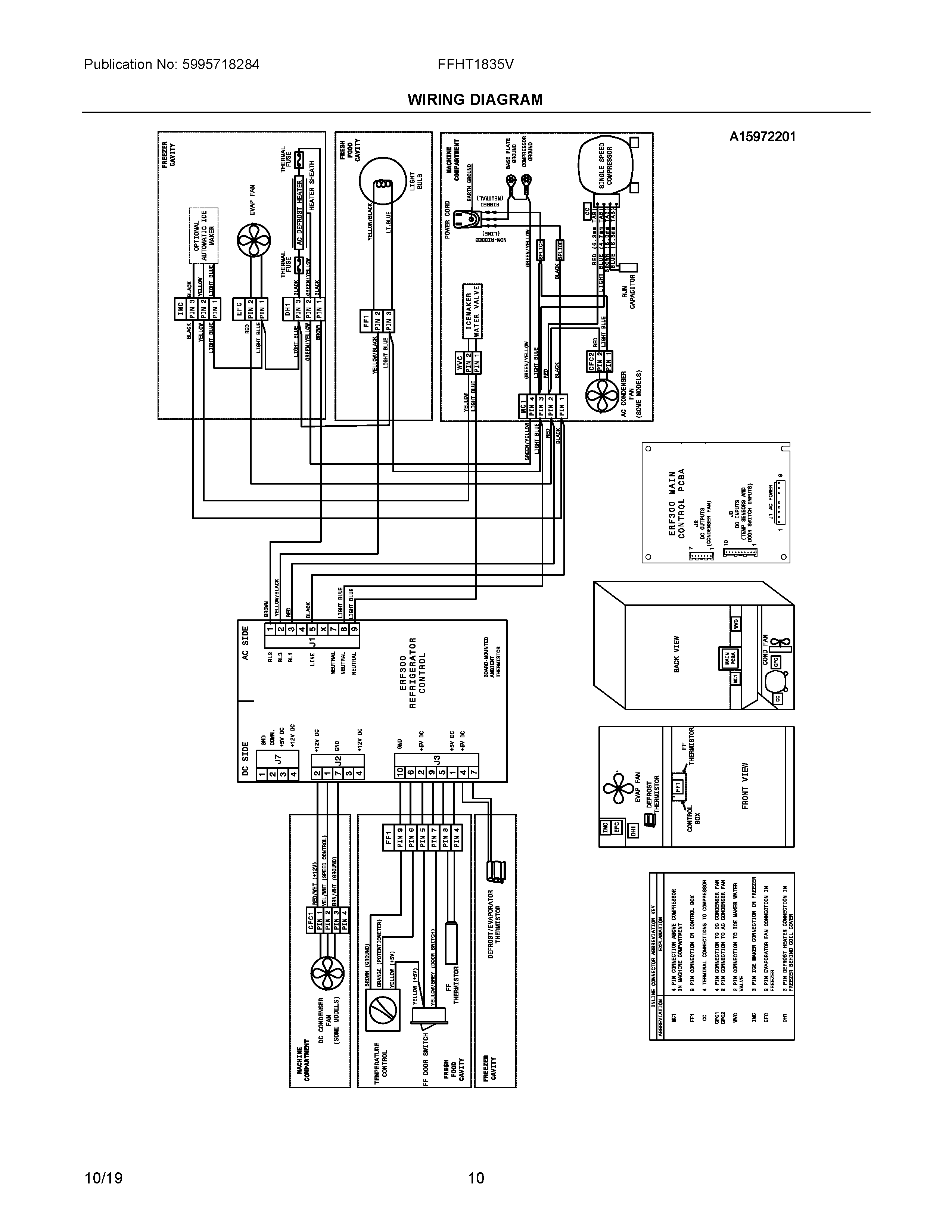
42 hvac condenser wiring diagram
06.04.2015 · I have a wiring diagram of the entire system, and I used my Ohm / Volt meter to check all the systems I could see. I checked the pressure switches for continuity and they all perform according to design. I also checked continuity through the igniter by itself, and all the wires connected to it, all the way to the IFC mother board. Everything appears fine. I also checked for power to the gas ... 4 Mar 2019 — Copeland Condenser Schematic Wiring Diagrams BlogCopeland Potential ... Air Compressor - bookingritzcarlton.info Basic Electrical Wiring, Ac.
May 4, 2019 - This Pin was discovered by Heynsam. Discover (and save!) your own Pins on Pinterest.

Hvac condenser wiring diagram
The high-voltage wires from the air conditioner disconnect box (usually mounted on an outside wall within arm's reach of the air conditioner unit) are now pushed up through the wire clamp in the bottom of the box. The high-voltage wires have two insulated power wires and one bare copper ground wire. Hvac Unit Diagram - Diagram Wiring Diagram Ac Full Version Hd Quality Diagram Ac Diagramrt Bmwe21fansclub It / Add registers to your existing or expanded hvac duct work.. Apr 11, 2019 · 71 10 hvac module, emtc and datc 72 7.5 steering angle sensor module (sasm) 73 5 data link connector (dlc) 74 15 high beam relay, headlamp assembly, right and ... How To Wire An Air Conditioner For Control 5 Wires Quality. Rheem ruud hvac age manuals parts air conditioner thermostat wiring diagram 1990 ac full split outdoor compressor connecting on heat dual condensing unit home new contactor diy pump diagrams gas furnace 10 kw electric heater condenser fan motor 51 23053 quality 240v for control 5 wires goodman packaged braeburn capacitor 14ajm36a01 ...
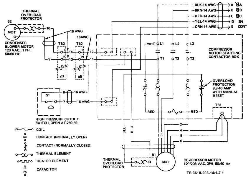
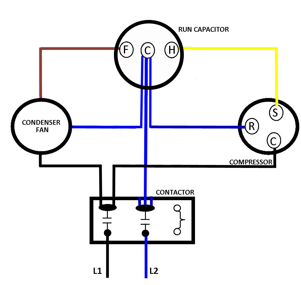
Hvac condenser wiring diagram. Inside the air handler unit, the high voltage wiring powers the indoor fan, the heater and provide power for the transformer. Inside the condenser/evaporator unit, the high voltage wiring powers the outside fan and the compressor. 3- Low voltage control part: This part has (2) mode for operation which are: Size: 308.36 KB. Dimension: 1226 x 971. DOWNLOAD. Wiring Diagram Pics Detail: Name: york condensing unit wiring diagram – Hvac Condenser Wiring Diagram New Air Conditioning Condensing Unit Wiring Diagram Valid Wiring Diagram. File Type: JPG. Source: yourproducthere.co. Size: 925.99 KB. Dimension: 2257 x 2236. Standard A/C Condenser AC Contactor 4 This diagram is to be used as reference for the low voltage control wiring of your heating and AC system. Always refer to your thermostat or equipment installation guides to verify proper wiring. NOTE Some AC Systems will have a blue wire with a pink stripe in place of the yellow or Y wire. 1- Importance Of Electrical Wiring For Air Conditioning Systems. In the detailed design phase, the electrical designer must size and select the wires/cables, conduits, starters, disconnects and switchgear necessary for supplying power and control to HVAC equipment. This information designed by the electrical designer will be and must appear on ...
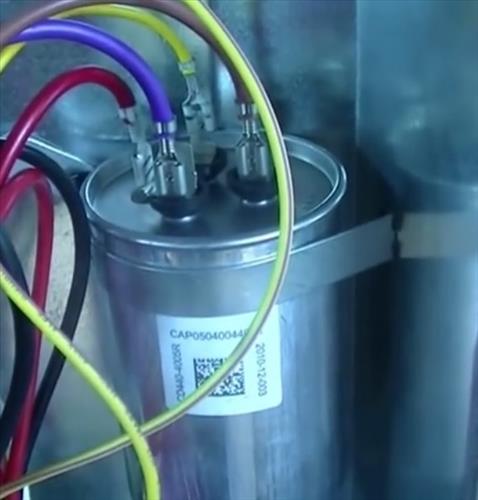
Thermostat Wiring Diagrams for Heat Pumps - Heat Pump Thermostat Wire Diagrams. Heat pumps are different than air conditioners because a heat pump uses the process of refrigeration to heat and cool.While an air conditioner uses the process of refrigeration to only cool, the central air conditioner will usually be paired with a gas furnace, an electric furnace, or some other method of heating. 24.05.2018 · For a visual picture of typical wiring configurations, reference the following guide: HVAC Condenser Fan Motor Wiring Diagram. Finally, this guide is intended to be used as a general overview of common condenser unit wiring schematics. Some condenser fan motors wire to a circuit board while others use proprietary plugs for their connectors. We strongly recommend referring back to your unit’s ... Manuals, parts lists, wiring diagrams for Goodman & Aman a HVAC equipment: Free downloadable manuals for Air Conditioners, Boilers, Furnaces, Heat Pumps. Here we provide free downloadable copies of installation and service manuals for heating, heat pump, and air conditioning equipment, or contact information for the manufacturer. We also provide an ARTICLE INDEX for this topic, or you can try ... HVAC Condenser Motor Replacement Wiring Guide ... Move the brown wire from the “F” ... Added Jumper 2MEV9 Step 2 L1 L2 208-230 VAC L1 L2 208-230 VAC L1 L1 Common L2 L2 L2 Brown (Common) Title: HVAC-Condenser-Fan-Motor-Wiring-Diagram Author: xdxg012 Created Date: 5/24/2018 11:26:51 AM ...
Ac Condenser Wiring Diagram | Car Wiring Diagram. Ac Condenser Wiring Diagram. Explore ideas on Pinterest. Air Conditioner Wiring Diagram Capacitor Ac Wiring, Electrical Wiring Diagram, Carrier Air Conditioner,. A. arturo lasose. 6 followers. More information. Outdoor Unit Wiring Diagram for A/C Systems(208/230V 1P 60Hz). CC. COMPRESSOR CONTACTOR. RC 1. RUN CAPACITOR 1 ... NOTES: 1.AC:Air Conditioner; HP:Heat Pump.3 pages Ac Condenser Wiring Diagram – ac condenser contactor wiring diagram, ac condenser fan motor wiring diagram, ac condenser fan wiring diagram, Every electric arrangement consists of various different components. Each component should be set and linked to different parts in specific manner. If not, the arrangement won’t function as it should be.
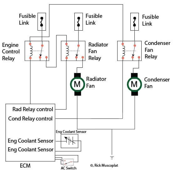
05.10.2018 · This option consisted of an extra cooling fan in front of the a/c condenser, heavy duty radiator and oil cooler. We have had both the heavy duty and standard duty radiators out of the 1985-89 models and could not see any major differences. 1990+ Corvettes have two radiator cooling fans. 1990-1991 Corvettes also may have an oil cooler. 1992-1996 Corvettes do not have oil coolers due to ...
comAutopsia de un capacitor: http://goo.gl... Ismaelelectronica · Ac Dual Capacitor Wiring Diagram Hvac Air Conditioning, Refrigeration And Air Conditioning ...
Jul 29, 2020 - 220V Electric Fan Wiring Diagram and Wiring A Capacitor Diagram ... How to Replace a Central Air Conditioning Capacitor (with diagnosis).
How To Wire An Air Conditioner For Control 5 Wires Quality. Rheem ruud hvac age manuals parts air conditioner thermostat wiring diagram 1990 ac full split outdoor compressor connecting on heat dual condensing unit home new contactor diy pump diagrams gas furnace 10 kw electric heater condenser fan motor 51 23053 quality 240v for control 5 wires goodman packaged braeburn capacitor 14ajm36a01 ...
Hvac Unit Diagram - Diagram Wiring Diagram Ac Full Version Hd Quality Diagram Ac Diagramrt Bmwe21fansclub It / Add registers to your existing or expanded hvac duct work.. Apr 11, 2019 · 71 10 hvac module, emtc and datc 72 7.5 steering angle sensor module (sasm) 73 5 data link connector (dlc) 74 15 high beam relay, headlamp assembly, right and ...
The high-voltage wires from the air conditioner disconnect box (usually mounted on an outside wall within arm's reach of the air conditioner unit) are now pushed up through the wire clamp in the bottom of the box. The high-voltage wires have two insulated power wires and one bare copper ground wire.

Unique Single Phase Capacitor Start Capacitor Run Motor Wiring Diagram Electrical Wiring Diagram Compressor Electrical Circuit Diagram














0 Response to "42 hvac condenser wiring diagram"
Post a Comment