37 shear diagram cantilever beam
A fixed-free cantilever beam, (Young's Modulus 𝐸, 𝑏×ℎ cross-section, length 𝐿) is supported at its left-hand end. A Force 𝐹 is applied at a distance 𝑎 from the left-hand end. We will first calculate the shape of the deflected beam and plot the result of deflection, shear and bending moment diagram.
Draw the shear force and b.m. The course covers shear force and . Fd = + 800 n. Pdf | in order to draw bending moment (or shear force) diagram of a beam in abaqus, the following steps should be made: Diagrams for the cantilever beam. Shear force and bending moment diagrams. Several multimedia tools have been .
20 kn 40 kn/m 150 kn·m.im 3 8 m prob. 6 34 draw the shear and moment diagrams for cantilever beam. 1) calculate the shear force and bending moment for the beam subjected to concentrated load as shown in the figure. Draw bmd, sfd and elastic curve 1.5m 30 fn (10) b) analyse the beam by.
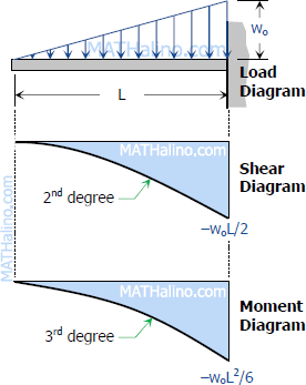
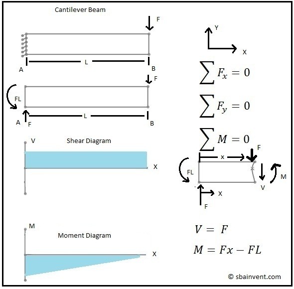
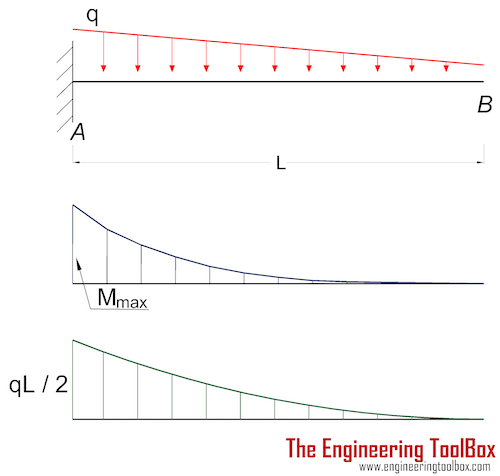
Shear diagram cantilever beam
Cantilever Beam Equations (Deflection) Taken from our beam deflection formula and equation page: Sample Cantilever Beam equations can be calculated from the following formula, where: W = Load. L = Member Length. E = Young's Modulus. I = the beam's Moment of Inertia.
MCQ On Bending Moment and Shear Force Diagram: 1. Those beam which is fixed at one end and other end is free is known as. 2. A beam which is extending beyond the support is called as. 3. The beam which is encastered at both end is known as. 4. Those beam which is supported one or more than two support is known as.
In this article Learn :cantilever beam Bending moment diagram B. Over Whole Span ,U. Somewhere on the beam,Combination of Point Loads and U. A shear force diagram is the graphical representation of the variation of shear force along the length of the beam and is abbreviated as S.
Shear diagram cantilever beam.
Shear Force And Bending Moment Diagram For Cantilever Beam With Two Equal Point Load Civil Snapshot. Cantilever Beam Shear Force Diagrams Mechanical Ering. Draw The Shear Force And Bending Moment Diagrams For A Cantilever Beam Ab Carrying Uniform Load Of Intensity Q Over One Half Its Length Study. Cantilever Beams Moments And Deflections.
Cantilever Beam Using Elements. Shear Force Bending Moment Diagram Of Cantilever Beam Exles Ering Intro. Calculator for ers bending moment and shear force cantilever beam with udl on right part of span for the cantilever beam and loading shown a evaluate reactions derive equations shear force v bending moment m any location in place origin ...
Shear Force and Bending Moment Diagram Drawing Instructions The ordinates in SFD and BMD diagrams are shear force or bending moment, and the abscissa is the length of the beam. Take a look at the left or right side of the section. On one of the portions, add the forces (including reactions) normal to the beam.
Cell Range with UDL data for the cantilever: Cant_PT: Cell Range with point load data for the cantilever : close_diagram: Optional Boolean value to add extra data points to close off moment and shear diagrams to allow for plotting. moment_shear_only: Optional Boolean value to select only returning Moment and Shear
2.1.0.0. A bug concerning failure of the code to return the equations of bending moment and shear force from the beginning of the beam was fixed. Download. 26 Apr 2017. 2.0.0.0. This file has now been updated to deal with cantilever (a system with just one support). It can also handle cases of beams lying on the floor with the reaction being ...
The end result is these moment, shear, and deflection plots (a 4.0m beam with 2.34m cantilever with some random loads):- Loads are entered in a format of load and location arrays similar to shown below for UDL's and point loads on main span and cantilever (if required), these form the inputs for the overarching BEAM_analysis function.
awcinfo@afandpa.org www.awc.org. BEAM FORMULAS WITH. ORMULAS WITH. SHEAR AND MOMENT. DIAGRAMS ... Figure 12 Cantilever Beam – Uniformly Distributed Load .20 pages
(iv) The shear force between any two vertical loads will be constant and hence the shear force diagram between two vertical loads will be horizontal. (v) The bending moment at the two supports of a simply supported beam and at the free end of a cantilever will be zero. RELATIONS BETWEEN LOAD, SHEAR FORCE AND BENDING MOMENT
Problem: F6-1. Express the shear and moment functions in terms of x, and then draw the shear and moment diagrams for the cantilever beam. [Chapter - 6, Bending, Mechanics of Materials by R C Hibbeler) Solution: Check Other Problems' Solutions here: (Book Solutions) Mechanics of Materials by R C Hibbeler (Eighth Edition) Let A be … (Solved Book Problems) - F6-1 - Express the shear and ...
Sep 11, 2017 — A shear force diagram is the graphical representation of the variation of shear force along the length of the beam and is abbreviated as S.F.D..
In Shear force and Bending moment diagrams, the positions of important points of a beam are plotted along X X axis and respective values of shear forces and bending moments at that points are plotted along Y Y axis. At important points of the horizontal beam, co-ordinate points are plotted along the length of the beam.
The above beam design and deflection equations may be used with both imperial and metric units. As with all calculations/formulas care must be taken to keep consistent units throughout with examples of units which should be adopted listed below: Notation. FBD = free body diagram; SFD = shear force diagram; BMD = bending moment diagram
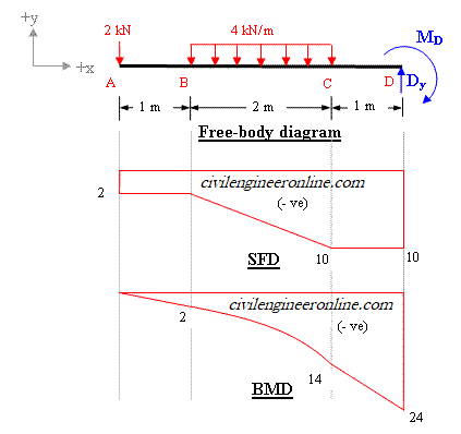
100501 SF & BM DIAGRAM OF CANTILEVER WITH POINT LOAD. SHEAR FORCE DIAGRAM - If there is no other load between two points of a beam, then shear force between these two points will remain constant. Therefore, ( SF ) diagram will be parallel to the base line between these two points. Point load ( W ) is loaded at free end point B .
After completing this course… You will be fully competent in drawing shear force and bending moment diagrams for statically determinate beams and frames.; You will have a robust system of analysis that allows you to confidently tackle the analysis of any statically determinate structure.; You will understand the relationship between external loading and the shear forces and bending moments ...
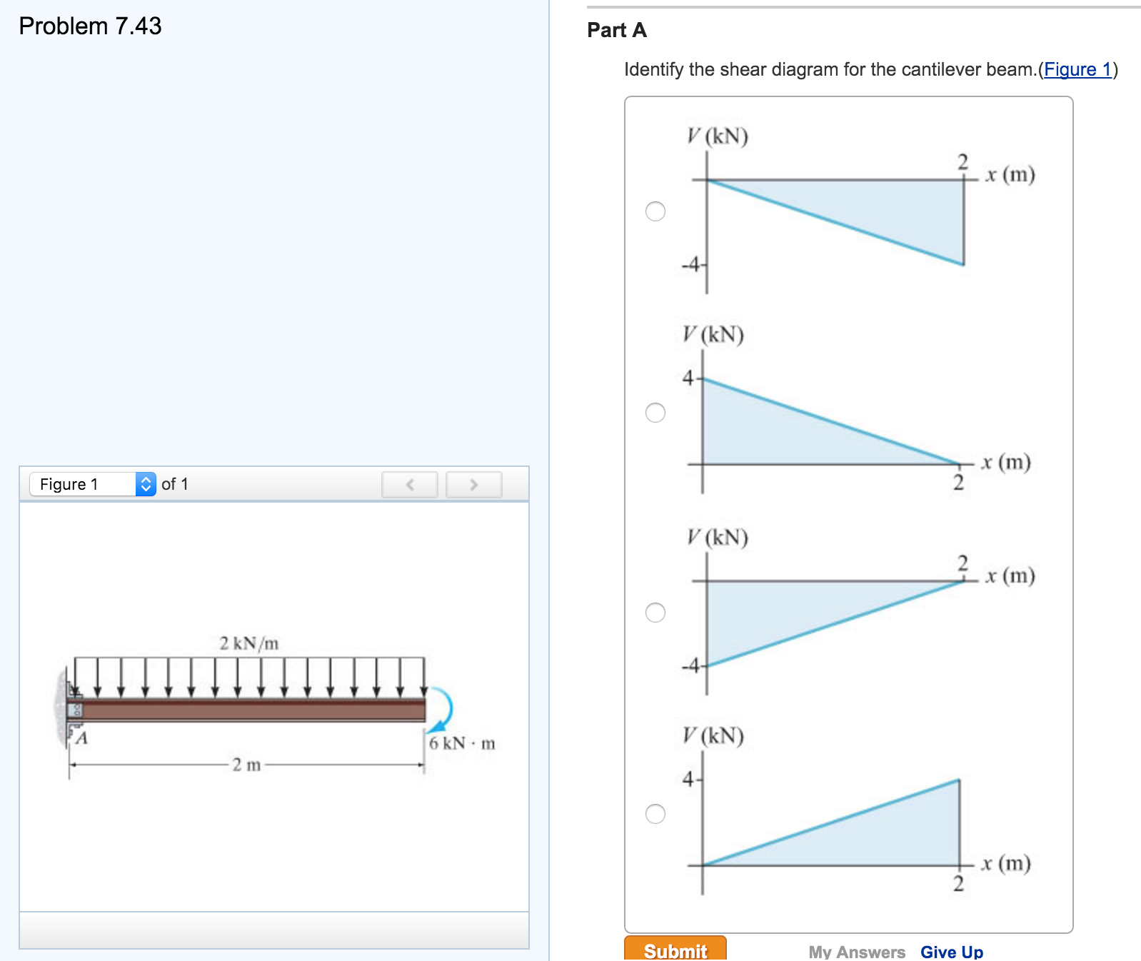
Draw Shear and Moment Diagram for the Cantilever Beam. (6-4. Bending, Mechanics of Materials by R C Hibbeler) Solution: Check the complete Book Solution Manual: (Book Solutions) Mechanics of Materials by R C Hibbeler (Eighth Edition) End support reactions are: Vertical Reactions, RA = 4.0 kN, and RB = 0 kN
Cantilever Beams Moments And Deflections. Shear Force And Bending Moment Diagram For Cantilever Beam With Point Load Civil Snapshot. Draw The Shear Force And Bending Moment Diagrams For A Cantilever Beam Ab Carrying Uniform Load Of Intensity Q Over One Half Its Length Study. Mechanics Of Materials Bending Shear Stress Slender Structures Boston.
The shear diagram will plot out the internal shearing forces within a beam, or other body that is supporting multiple forces perpendicular to the length of the beam or body itself.
The plots of the shear and moment diagrams as well as the displayed tabulation of shear, moment, slope, and deflection are based on the beam (or each individual span) being divided up into fifty (50) equal segments with fifty-one (51) points. For continuous-span beam of from two (2) through five (5) spans, this program utilizes the "Three-Moment
The above beam design and deflection equations may be used with both imperial and metric units. As with all calculations/formulas care must be taken to keep consistent units throughout with examples of units which should be adopted listed below: Notation. FBD = free body diagram; SFD = shear force diagram; BMD = bending moment diagram
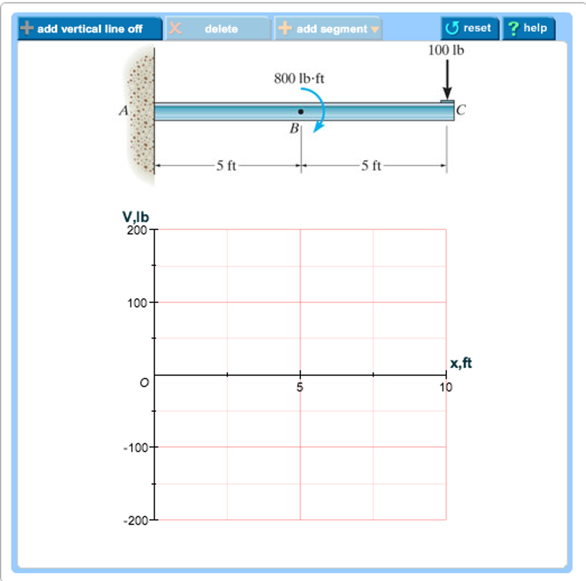
Draw the shear diagram for the beam. Follow the sign convention. (Figure 1) Click on "add vertical line off" to add discontinuity lines. Then click on "add segment" button to add functions between the lines. Note 1 - You should not draw an "extra" discontinuity line at the point where the curve passes the x-axis.
Shear Force and Bending Moment Diagram for Cantilever Beam with Point Load at the Free End L is the length shown in Fig when a point is a fixed end when point b is the free end. For calculation of shear force.
Shear stress at the end of cantilever beam when x l pared with scientific diagram a cantilever beam is subjected to distributed sh chegg shear stress at the end of cantilever beam when x l pared with scientific diagram cantilever beam udl and end bending moment 5 7 normal and shear stresses bending of beams informit.
Cantilever Beam Reactions The external forces resisting the beam are shown in the diagram above, where the moment and shear are resisting the applied force at the support (note - always important to define support conditions). We can take a cut of the section to check the internal reactions. Beam - Cut internal forces Sign Conventions
1 Answer to Q1. A cantilever beam of length 2 m carries the point loads as shown in Figure 1. Draw the shear Force and Bending Moment Diagrams for the cantilever beam Figure 1 Q2. A cantilever beam of length 2 m carries a uniformly distributed load 1KN/m run over the length of 1.5 m from the free end. Draw the...
For a loaded cantilever beam of unifonn cross-section, the bending moment (in N.mm) along the length is M (x) = 5x2 + 10.r , where x is the distance (in mm) measured from the free end of the beam. shear force and bending moment equations. And (2) draw the shear force and bending moment diagram s. Neglect the weight of the beam.
![Cantilever Beam: Shear Force and Bending Moment Diagram [SFD BMD Problem 2] By Shubham Kola | Facebook](https://lookaside.fbsbx.com/lookaside/crawler/media/?media_id=257535155732524&get_thumbnail=1)
Cantilever beam: shear force and bending moment diagram [sfd bmd problem 2] by shubham kola | facebook
![[Ex. 07] Shear Moment Diagram Cantilever Beam Distributed Load Part I](https://i.ytimg.com/vi/qMk5IVKcZQM/maxresdefault.jpg)














0 Response to "37 shear diagram cantilever beam"
Post a Comment