38 emg wiring diagram solder
I am at the point of doing my electronics and although the EMG DG20s are supposed to be solder free, plug and play type connection, for some reason mine is not like the ones seen on YouTube. The wiring diagram that came with the pickups shows a single white coax cable coming from the circuit board under the tone knobs wired to the jack socket.
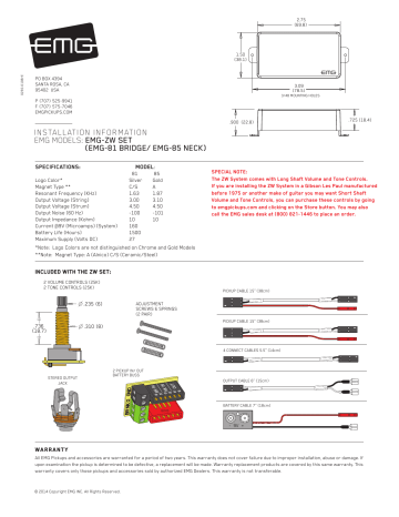
If your guitar is wired in the same fashion, simply follow the diagram and install the cables as shown. 3) If your instrument has a selection switch or the wiring is different, vist our website; emgpickups.com for more diagrams and video installations. PJ-HZ GZR SET Page 2 Installation Instructions: EMG Models: PJ-HZ GZR SET Diagram #1
Diagram #8 1 3 Soldering to the battery buss: If your instrument has an older EMG Pickup you can solder the pickup RED wire to the buss. Simply use some needle nose pliers, pull out the V+ header and solder the RED Wire from the pickup(s) to any of the pins and then re-insert the header into the housing. 2 +18 Volt Wiring Option:

Emg wiring diagram solder
Diagram #5 Solder the RED wire from the Battery Holder and/or pickups and re-insert the Header into the insulation cover 1 3 Soldering to the battery buss: If your instrument has an older EMG Pickup you can solder the pickup RED wire to the buss. Simply use some needle nose pliers, pull out the V+ header and solder the RED Wire from the pickup(s)
Posted March 19, 2018. EMG's passive pickups are pretty much like every other manufacturer's pickups. To convert EMG's modular solderless system for standard soldered connection, just snip off the connector. EMG should provide a way to decode the pickup wire colors. Don't bother "upgrading" pots if the current ones work smoothly and don't crackle.
Diagram #5 1 3 Soldering to the battery buss: If your instrument has an older EMG Pickup you can solder the pickup RED wire to the buss. Simply use some needle nose pliers, pull out the V+ header and solder the RED Wire from the pickup(s) to any of the pins and then re-insert the header into the housing. 2 Installation Instructions:
Emg wiring diagram solder.
Diagram #5 Solder the RED wire from the Battery Holder and/or pickups and re-insert the Header into the insulation cover 1 3 Soldering to the battery buss: If your instrument has an older EMG Pickup you can solder the pickup RED wire to the buss. Simply use some needle nose pliers, pull out the V+ header and solder the RED Wire from the pickup(s)
EMG has been moving towards solderless connections on all their stuff since 2009, and for the most part this works quite well - except when you're integrating an EMG pickup into a circuit that uses non-EMG components.
Emg Wiring Diagrams 2 Volume 👉 1 Plug the pickup cable onto the EMG Pickup header as shown in diagram 1 and route the cable to the control cavity. It shows the parts of the circuit as streamlined shapes and also the power as well as signal connections between the devices.
Diagram #2 EMG Pickups Soldered Inputs Soldered inputs: On the back side of the ABC PC Board there are 4 pads to solder to. Solder the signal wire (Hot) of the bridge pickup to the BRG Pad, Do the same for the Neck Pickup, Hot to the NEK Pad, and ground to the GND Pad. Refer to Diagram #8 and solder the Red wires of
Diagram #8 1 3 Soldering to the battery buss: If your instrument has an older EMG Pickup you can solder the pickup RED wire to the buss. Simply use some needle nose pliers, pull out the V+ header and solder the RED Wire from the pickup(s) to any of the pins and then re-insert the header into the housing. 2 +18 Volt Wiring Option:
Listing of EMG Top 10 active pickup wiring diagrams for EMG 81, 85, 89, S, SA, Zakk Wylde, bass pickups and SPC & EXG EQ circuits.
Need help with EMG solderless wiring Discussion in 'Pickups, Electronics & General Tech' started by Stuck_in_a_dream, Sep 8, ... Following the diagrams below, check the following specific diagram #'s for details: ... you will need to solder both the black and white wires to the black and white wires of the other cable you cut the connector off ...
Hi, I purchased second hand an older version of the EMG DG20 loaded pickguard that has the SPC and EXG controls. I know its an older model because its not prewired. I google'd and search everywhere for wiring diagrams and I'm at a loss. Attached is a pic of the back of the pickguard. It shows only 2 wires.
11.09.2018 11.09.2018 4 Comments on Original Emg Wiring Diagram Solder At first I wired per EMGs diagram but it was looping the signal back I eventually got frustrated and had to solder everything. I guess a better way to ask the question is if EMG can either provide instructions or post a schematic how they Please let us know if you have any ...
Diagram #5 Solder the RED wire from the Battery Holder and/or pickups and re-insert the Header into the insulation cover 1 3 Soldering to the battery buss: If your instrument has an older EMG Pickup you can solder the pickup RED wire to the buss. Simply use some needle nose pliers, pull out the V+ header and solder the RED Wire from the pickup(s)
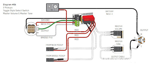
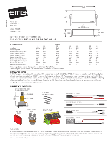
Diagram #1 Insert the plug onto the 3 pin header of the pickup as shown above. Note the orientation arrow. Installation (Two Pickup Guitars with Selection switch): Guitars with two pickups and a selection switch will use the EMG B245 Pickup Buss as shown in diagram #2. The Pickup Buss is a convenient way to wire your guitar without soldering.
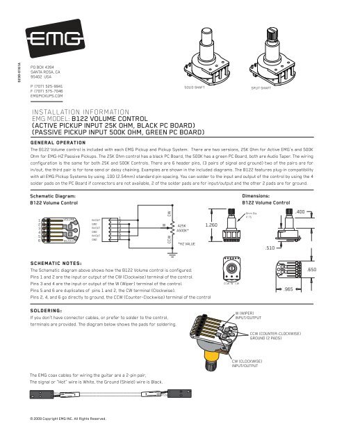
diagram and route the cable to the control cavity. 4) Solder the braid of the pickup cable to the case of the volume control as shown in the diagram and connect the switch wires as shown. 5) For two-pickup guitars, follow steps 1-4 before continuing. 6) Remove the existing output jack and replace it with the EMG output jack. Solder the output ...
EMG Model: EXB EXB Page 2 Solder RED wires from both EMG Pickups and the RED wire of the Battery Clip and re-insert the Header into the insulation cover 1 2 3 Note: Reversed connector! Pins 1 and 2 are reversed. Make sure the connectors are plugged on as shown. All of the EMG Active controls use the same 5-pin connector shown below. Diagram #2 ...
Electric Guitar Pickups, Bass Guitar Pickups, Acoustic Guitar Pickups and Accessories - EMG Active & Passive Pickups - over 25 Years of Active Pickup Technology - The original active pickup.
Also the EMG 81 both have 2 wires, and I guess the wire braid around the white wire makes a 3 'wire' to solder. Is that tricky to do without heating up the white wire and melting stuff? I have 60/40 lead rosin core very small diameter solder for this and tons of 22 AWG wire I scrounged from the garage door opener (ha!)
Mar 5, 2019 - Wiring Diagram For Emg Active Pickups Diagram Emg Pickup Of Emg Wiring Diagram Solder In Emg 81 85 Wiring Diagram, best images Wiring Diagram For Emg Active Pickups Diagram Emg Pickup Of Emg Wiring Diagram Solder In Emg 81 85 Wiring Diagram Added on Wiring Diagram - floraoflangkawi.org
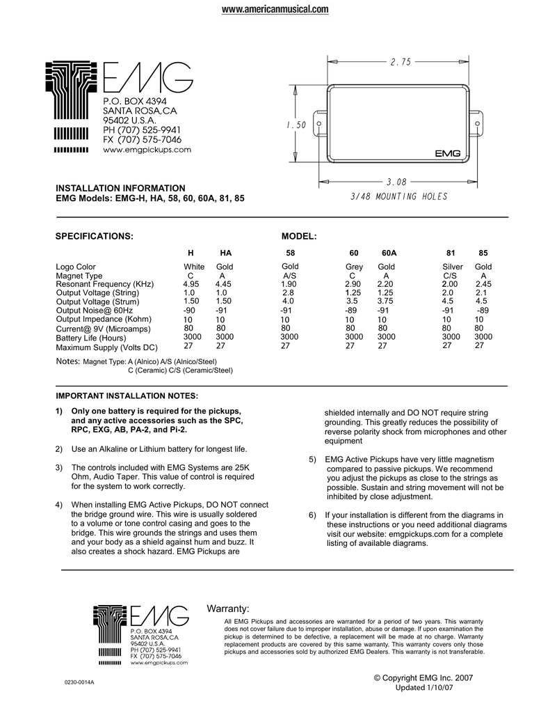
4) When installing EMG Active Pickups, DO NOT connect the bridge ground wire. This wire is usually soldered to a volume or tone control casing and goes to the .. Then snap clip #1 to your original clip already in your guitar. This wire is usually soldered to a volume or tone control casing and Balance Control.
Listing of EMG Top 10 active pickup wiring diagrams for EMG 81, 85, 89, S, SA, Zakk 2 89s, 2 volume, 1 tone, Solderless · 3 Pickups, SPC/EXG, Hardwired. All of the solderless components for install in one package! This kit is for active pickups and includes everything needed for installation in a 1 or 2 pickup. Top 10 Wiring Diagrams.
Repository of EMG wiring Diagrams! Tags diagrams emg ... of the more esoteric configs like using a single push-pull as both master volume and the pickup selector as well as the diagrams for those 3 mini-toggle Charvel/Jacksons like the Model 4, as well as some super-wacky ones like wiring an 89 with a passive pickup with 3 accessory circuits up ...
Original Emg Wiring Diagram Solder. And solder it to the case of the tone pot. (i think). 7) Solder the RED wire (s) of the pickup (s) to the RED You can also run a wire and solder directly to each quick connect pin if needed, just make sure to cover the pins with heat shrink tubing so that nothing makes contact and shorts out.
Question about soldering EMG pickups Discussion in 'Pickups, Electronics & General Tech' started by ibzrg1570, Apr 26, ... Right now the wiring is the only problem left, I've fixed all the others myself and I got a new wiring diagram without the tone control just to make it a little easier for myself. When (or if) I finish I'll post lots of pics.
Guitars with two pickups and a selection switch will use the EMG B245 Pickup Buss. The Pickup Buss is a convenient way to wire your guitar without soldering. Since you are installing passive EMG-HZ Pickups the RED Shroud of the B245 Pickups Buss will not be used. It is for battery power. TO STRING GROUND SEE DIAGRAM #5 Diagram #6a Diagram #7b 2 ...
Diagram #5 Solder the RED wire from the Battery Holder and/or pickups and re-insert the Header into the insulation cover 1 3 Soldering to the battery buss: If your instrument has an older EMG Pickup you can solder the pickup RED wire to the buss. Simply use some needle nose pliers, pull out the V+ header and solder the RED Wire from the pickup(s)

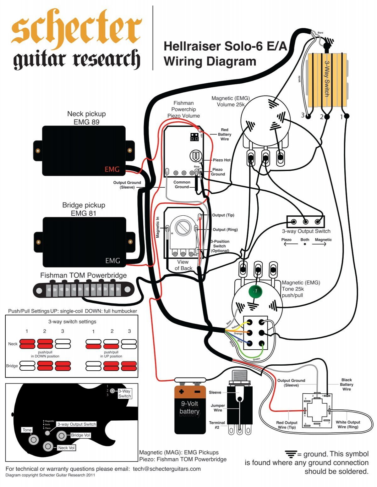
![QUESTION] Swapping EMG 81/89tw out of a Schecter Hellraiser C-1 ...](https://external-preview.redd.it/2cPCBa80YHF5pAlrTrVSlHbffwGEYGvT4FPye8Gn86I.jpg?auto=webp&s=7acf4c2f68c11c13426b1e1bb5da688e9674442d)


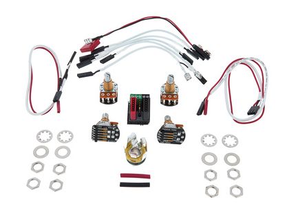


![QUESTION] EMG Pickups To Solder or Not To Solder : r/Guitar](https://i.pinimg.com/originals/81/ac/99/81ac99ae5f9f5f43a78a67ccf3e08a3a.jpg)




0 Response to "38 emg wiring diagram solder"
Post a Comment