39 line side tap solar diagram
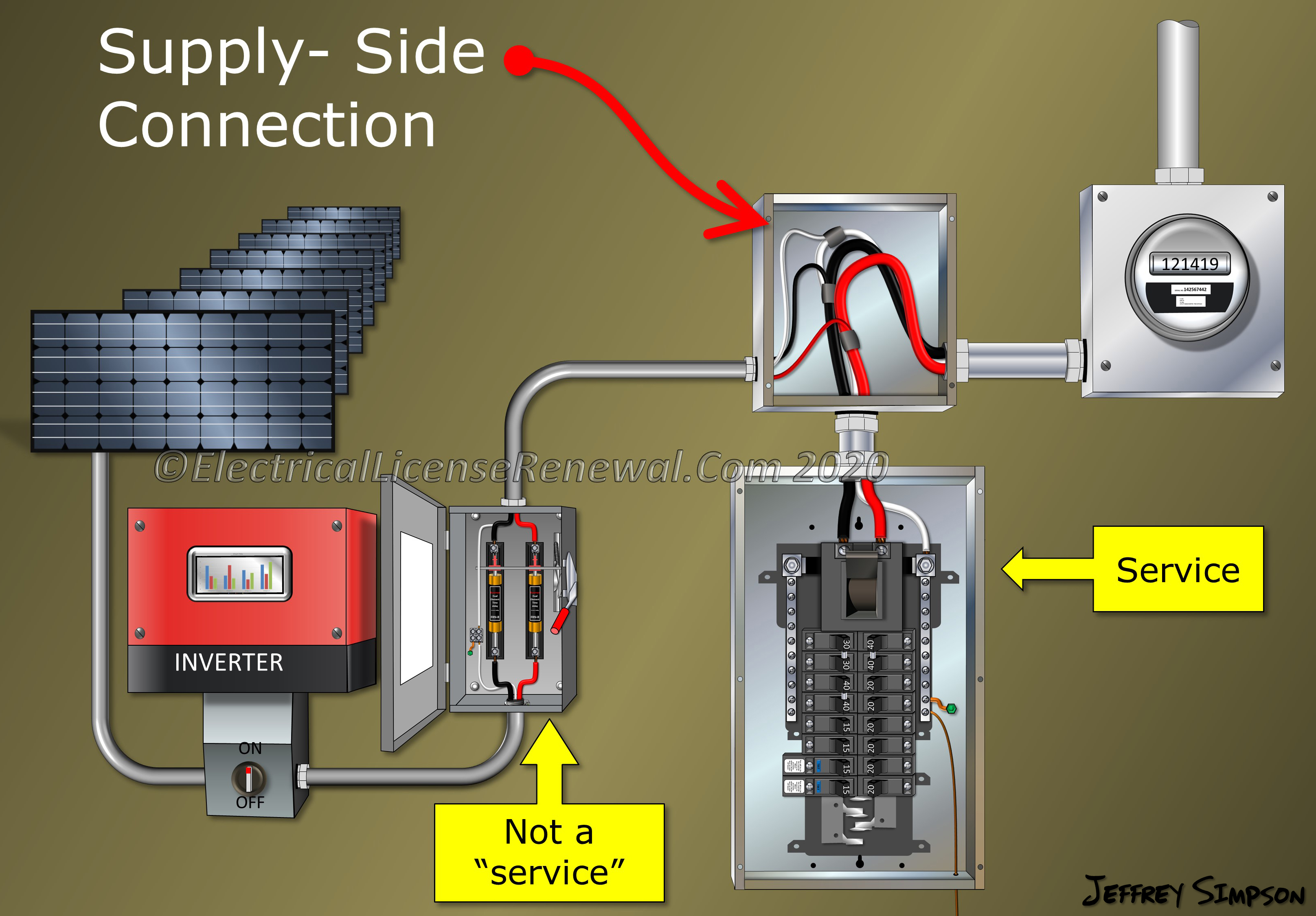
A supply side tap is a connection that is made to the busbars or conductors on the line or utility side of the main service disconnect. The line side tap the simplest way of interconnection when installing a PV system that exceeds the 120% rule.
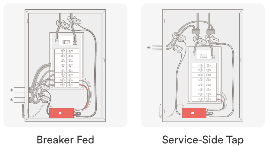
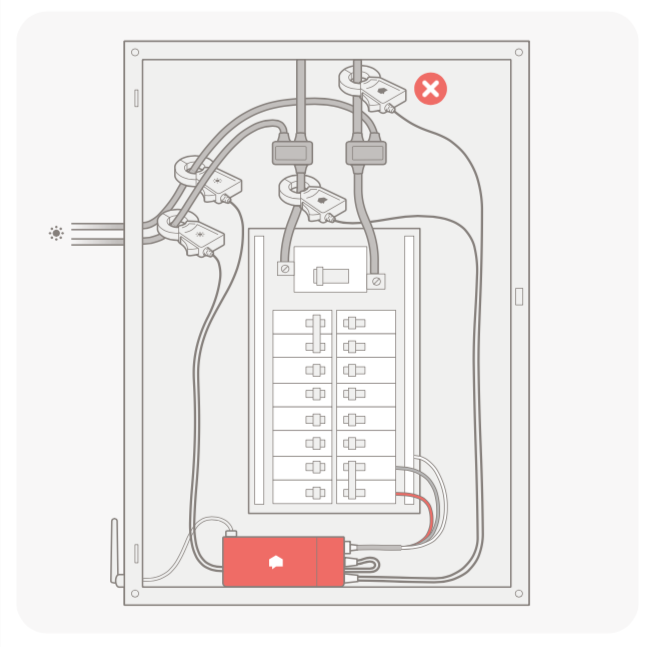
They are likely putting the Sense CTs inside the tap enclosure. You'll have a feed from the solar tapping the line going to the service panel. On set of CTs goes on the circuit to the inverter and the other set goes on the circuit to the service panel. Basically doing the same thing as shown in those Sense diagrams. 2.
Our Single Line Diagrams are routinely accepted by AHJs without modification. Beautiful, professional and reliable SLDs at the touch of the button are one of the many features our subscribers enjoy. All components are labeled and correspond to the table. Electrical properties of PV system components required for basic system calculations.

Line side tap solar diagram
One Line Diagram Example Line Side Tap **A line side tap CANNOT be contained in the billing meter** The purpose of this sample one-line diagram is show a utility line side tap. This occurs when the PV system is not wired into a back fed breaker within the house main service panel. Customer Generation Disconnect (CGD) REC Meter House Main ...
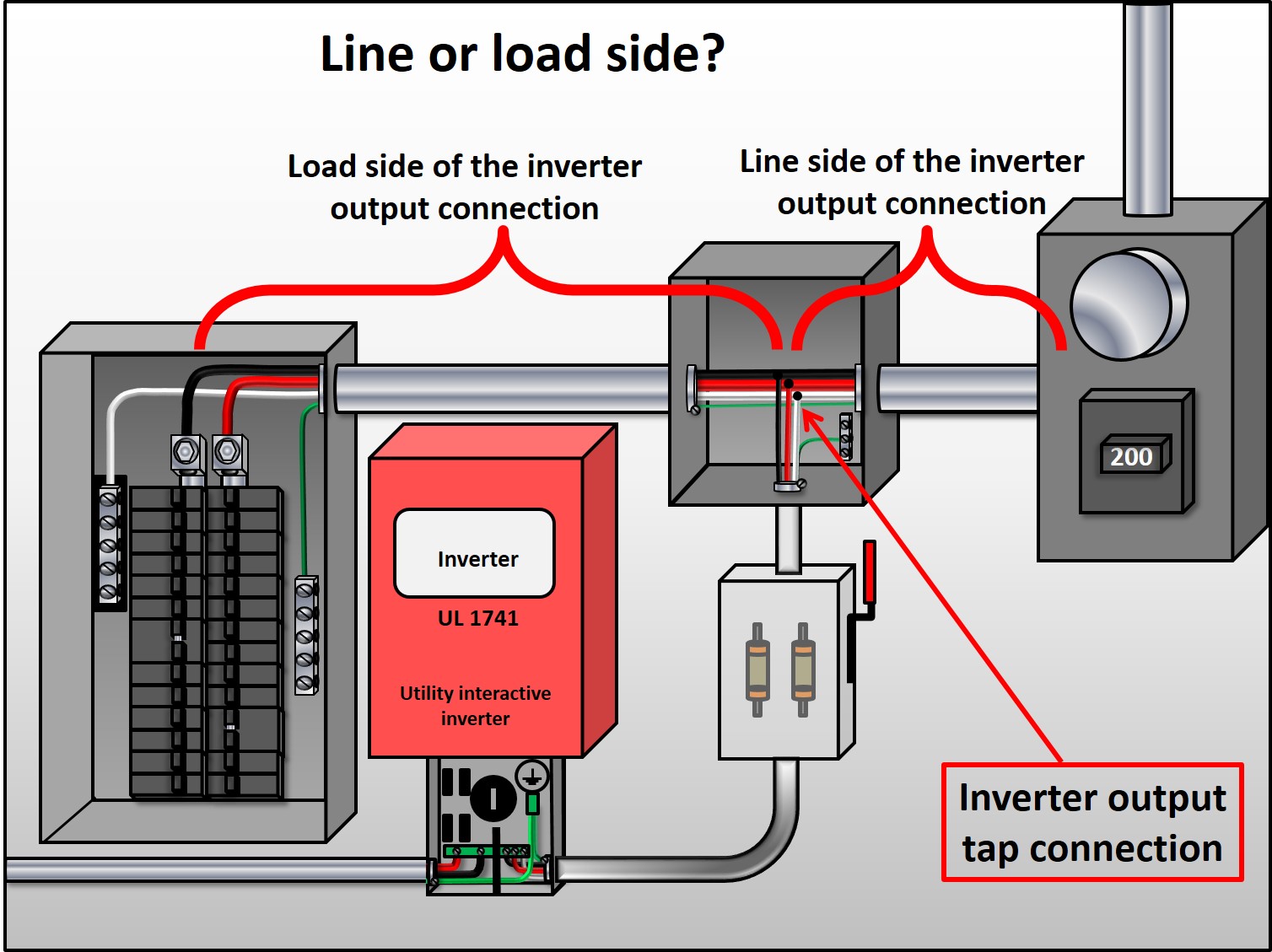
A line side tap (or supply side tap) refers to a connection between the meter and main breaker. This is the preferred method of interconnection for solar installers as it is the most straight forward and requires the least amount of calculations.
This panel design constitutes a line-side tap. A separate set of busbars, rated at 60 amps, is supplied for connecting to an inverter with a set of breakers. That set of busbars is connected directly to the load side of the meter socket before the main disconnect, bypassing the main busbars altogether.
Line side tap solar diagram.
7. Residential "solar ready" service panels designed with an alternative energy (customer generation) interconnection circuit breaker on the line side of the main breaker is allowable. "Solar ready" panels must be EUSERC approved and have factory installed labels showing location and ratings of the generation source 8.
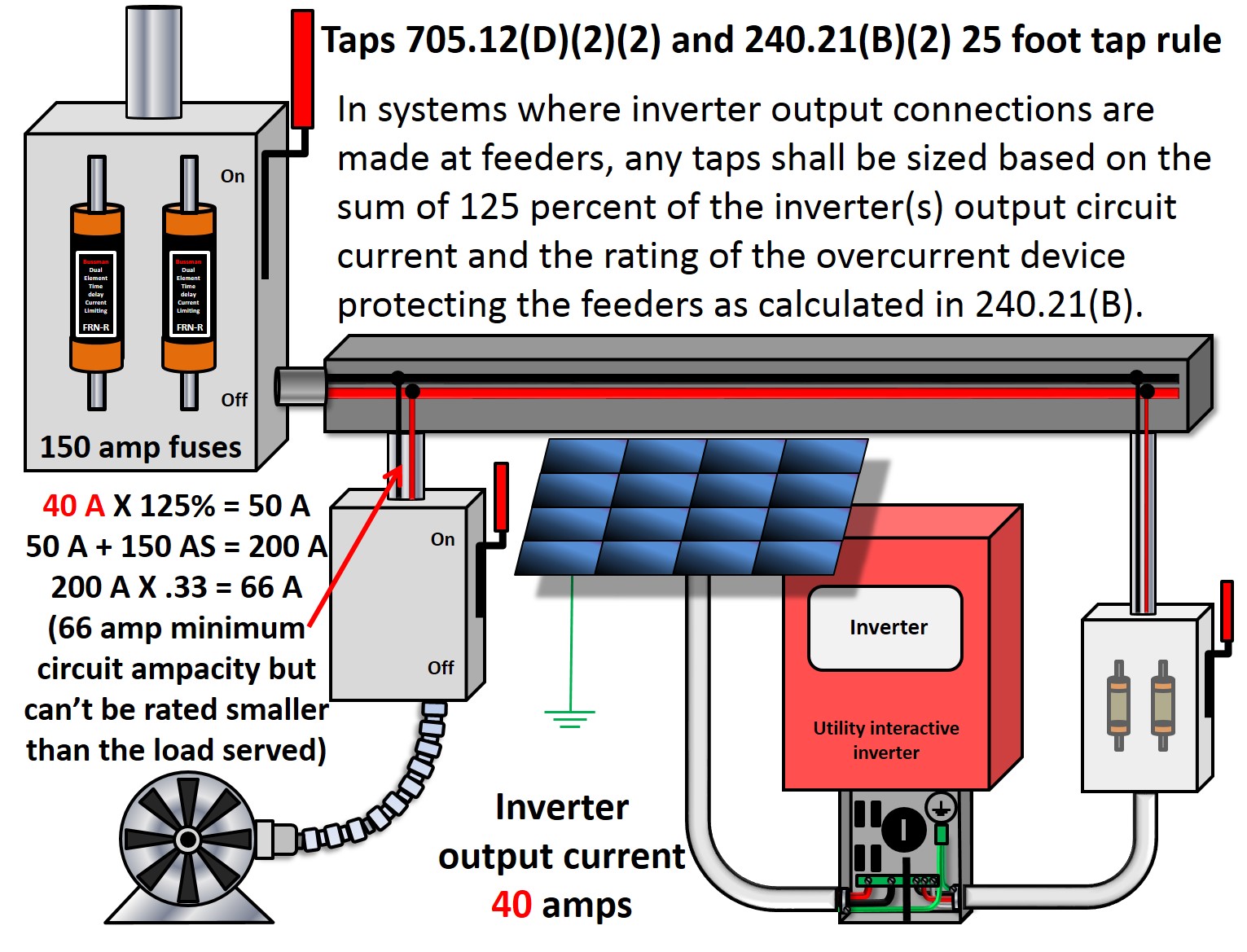
Prior to 2011 your load side tap option was not addressed by the code. 240.21(B) also applies to taps. In your diagram you have a tap. But, by the way, if you just add a backfed breaker to a panelboard on the load side of the service disconnecting means, then it is a load side connection, but it is probably not a tap.
supply side tap n ac disconnect: 60a fused, (2) 40a fuses, 240v nema 3r, ul listed, (if required by utility) supply side tap connection option (e)main breaker to house 240v, 200a/2p (v.i.f) (e)main service panel, 200a rated, 240v (shall be field verified) g bond #6 awg cu to new or existing ground rod (3)#6 thwn-2 in 3/4" conduit comply with ...
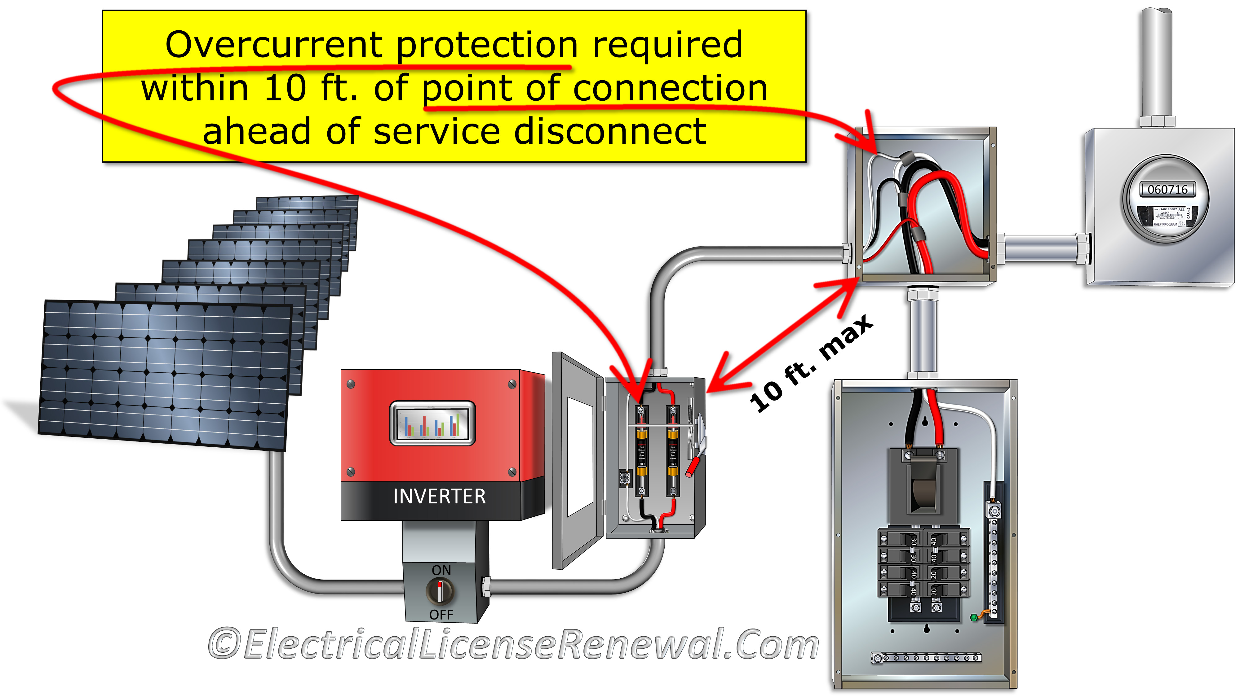
Re: Backfed breaker or Line side tap? I see one disadvantage of the line side tap and that is now I need to add overcurrent protection on the line between the inverter and the grid to protect the conductors between the PV meter and the inverter from potential overcurrent caused by a short on the AC side of the inverter.
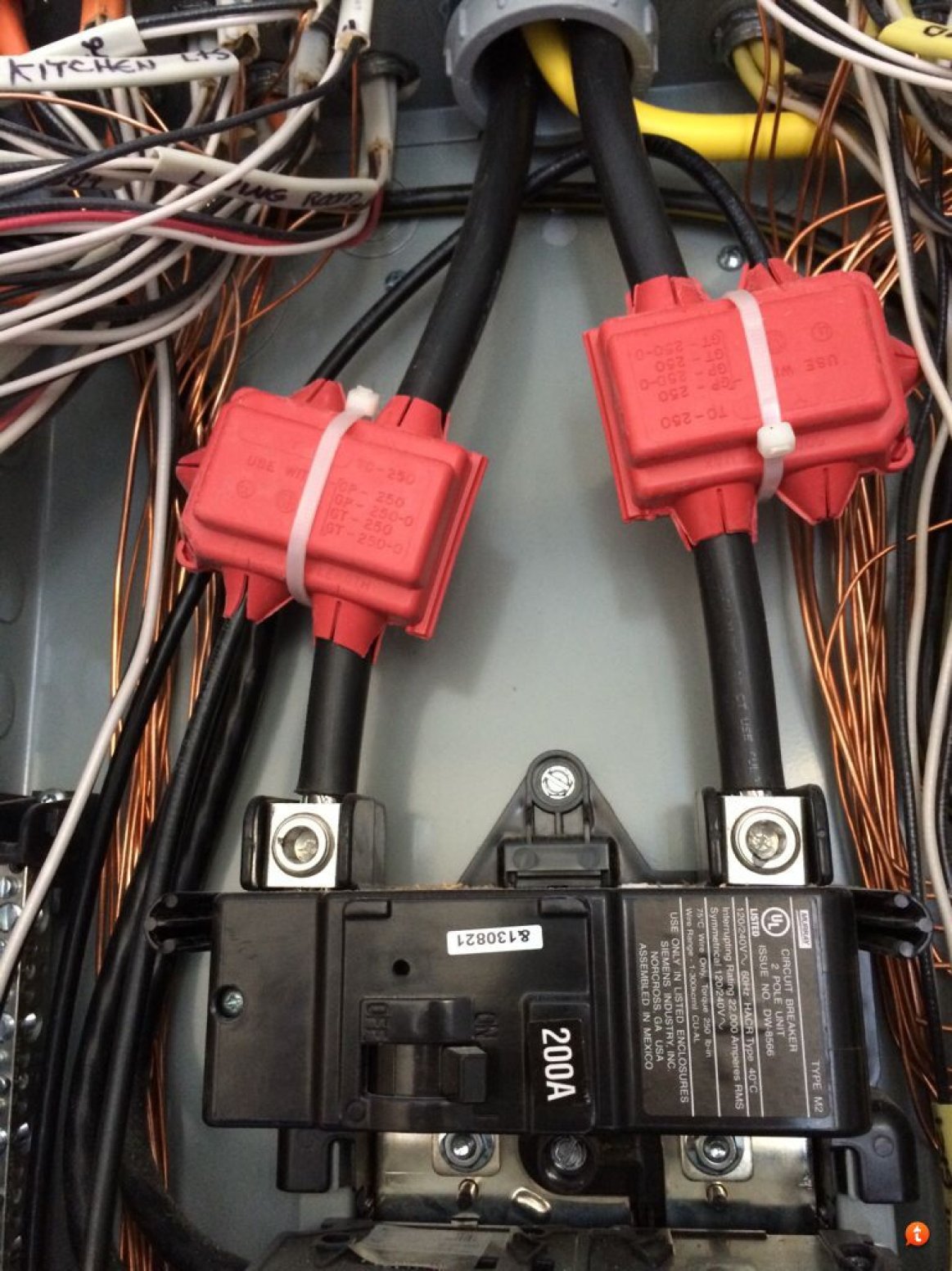
7.0 Load Side Taps 7.1 Is the tap made outside the main panel and in a NEMA 3R junction box? 7.2 Is the tap kit UL listed and appropriately sized to the conductors? 7.3 Does the tap box provide ample spacing for all taps and conductors and complies with NEC 314.16 and 366.56?
A line side tap is a method of connecting to the feeds between the service entrance and the load center, thus bypassing the load center and its limitations on maximum current. It is usually not compatible with an islanding system.
• Section 5 - Clarified requirements for line side taps • Section 5 - Remote Control Switch-Generation requirements ... 5.2 Single Line Diagram ... solar thermal, photovoltaic, wind, geothermal, fuelcells using renewable fuels, small hydroelectric generation, ...
Line side tap would only be needed if you wanted more than 50A breaker for PV. Or, if you want to feed grid directly into your inverter, and be able to switch the whole house main panel to output of inverter, using it as UPS for the entire house. Simple way to go is what you were thinking. 50A breaker feeds Outback.
uses a line-side tap to connect the inverter input when backfeeding via the main panel is not feasible or in compliance. This configuration is acceptable for use with most utility services. 30A 30A 30A 30A Power Conversion PWRcellTM Inverter Generac PowerCore Router Ethernet (CAT5) 50A AC Grid Main Distribution Panel M Protected Loads Panel AC ...
Note: this wiring diagram is simply an example. Diagrams may vary. SMA rapid shutdown box mounted under solar modules RS SMA rapid shutdown push button disconnect switch (mounted outside and adjacent to the service panel) #18 AWG THWN, 600V rated wire, ½" EMT
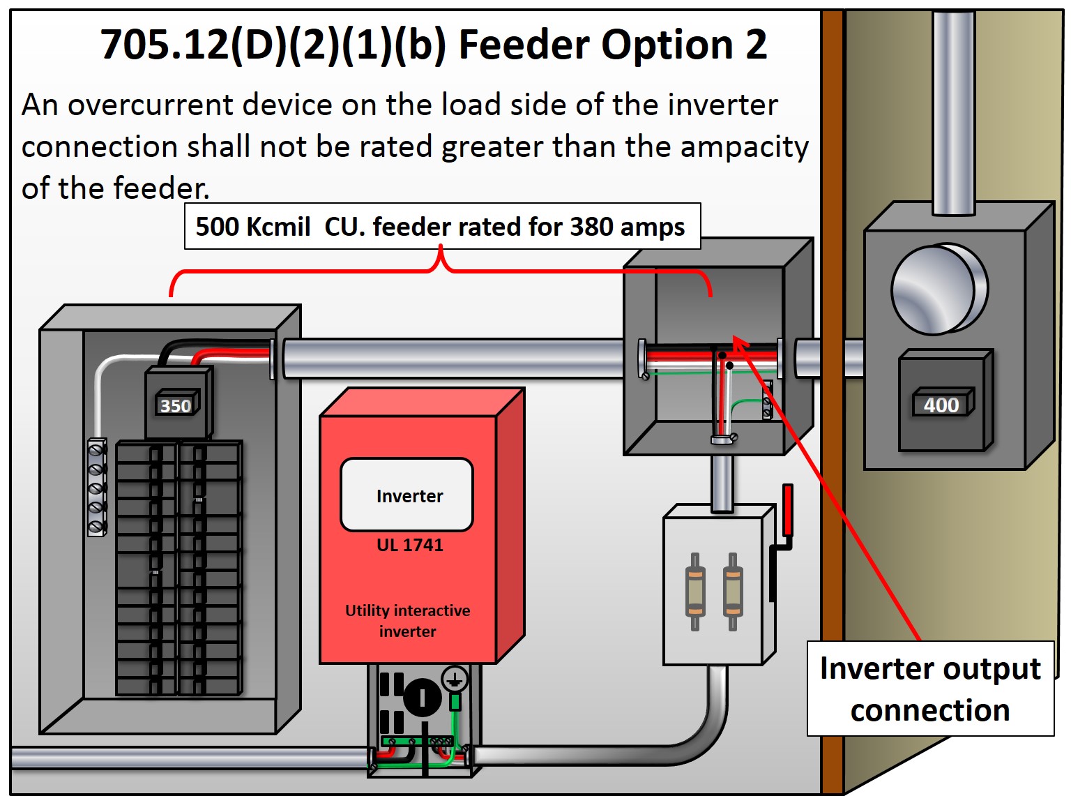
NEC Article 690.64(A) allows a Line‐Side AC connection to busbars, conductors, or lugs at any point between the customer's side of the utility meter, and the service disconnect. Many folks call this a "line‐side tap", which leads to confusion with the "10‐foot tap rule" and Article 240.21(B).
The LST2 diagram on the last page provides a partial detail of the tap connection. The position of the junction box will vary depending on the panel configuration and if the service is from overhead or underground to the meter. Line Side Tap 3 (LST3) - Line Side Tap connection installed to the bus between the meter and service main breaker.
The line-side tap is technically an extension of the service conductors since there is no overcurrent protection other than that provided in the PV system disconnecting means. In the 2017 NEC, the rules have been reversed. Now, If the PV system is connected to the supply side of the service disconnecting means as permitted in 230.82(6), the PV ...
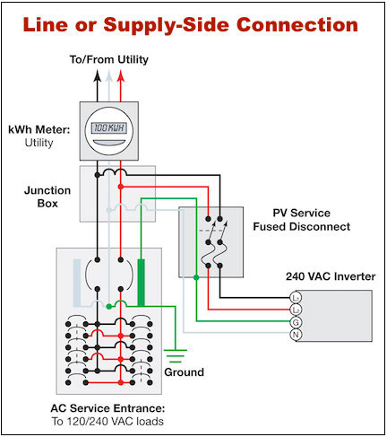
Option #3: Line Side Tap. An increasingly common solution is known as a Line Side tap, a.k.a. Supply Side tap. This work is usually done by a licensed electrician. The main breaker box is completely bypassed, and a fused AC Disconnect is used to connect the inverter to the grid between the utility meter and the main breaker box. This removes ...
That means you can't use any inverter higher than 3800 watts without getting a main panel upgrade or a "line side tap". The highest inverter output current acceptable for 20-amp breakers would be 16 amps, since 16 X 1.25 equal 20.
Line side taps are rarely doable when the service equipment is a single unit "meter-main" enclosure where the connection from meter socket to main breaker is solid bus bars. Meter-main combos are much more popular on the west coast, AFAIK, so in other parts of the country with separate meter socket boxes and main panels the line side tap is ...
Net Energy Metering Solar and Wind Generating Facility 10 kW or < Interconnection Agreement (Form 14-923) OR b) ... match the Single Line Diagram (SLD). Single Line Diagram: ... NEM application with a "Line-Side Tap" or point of connection is done between the main breaker and the service meter.
ABC Solar Grid Tie Single Line Diagram Load Side Tap Solar Electric Grid Tie. SINGLE LINE DIAGRAM The Single Line Diagram is needed for construction and permitting. STEP 1: CHOOSE SOLAR PANEL Over the years we have installed solar panels made by SolarWorld, Sanyo, Mitsubishi, Sharp, LG Solar, Suniva, JA Solar, Hyundai, and Sunpower (from black ...
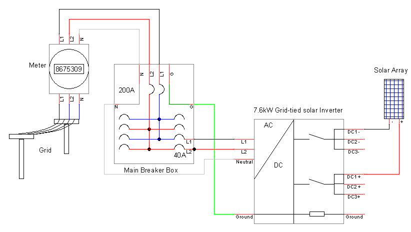
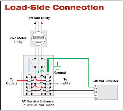
There are two basic approaches to connecting a grid-tied solar panel system, as shown in the wiring diagrams below. The most common is a "LOAD SIDE" connection, made AFTER the main breaker. The alternative is a "LINE OR SUPPLY-SIDE" connection made BEFORE the main breaker.
Line-side tap connection: This method requires that the wires from the inverter are connected to the service wires on the line side of the circuit breaker. This connection is very rarely allowed for residential systems but is increasingly common in commercial systems.
We recently installed solar on line side of ATS using external tap box and city approved the installation , inspected and passed. Now for the interconnection utility is giving us hard time. the Generator installed previously was not given permission to operate by POCO. so They advised us to...
DC Combiner Panel 3 ###A, ###VDC DC Combiner Panel 2 ###A, ###VDC DC Combiner Panel 1 ###A, ###VDC ##A XYZ Co. Model A Inverter ##kWAC, ###VAC
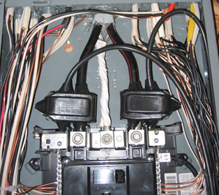
Here we connect our taps to the line side electric wires in the main panel. This work should be done by a licensed electrician.










![Block diagram of PAVR A multi-tapped transformer [7,16-19] with ...](https://www.researchgate.net/profile/Md-Murshadul-Hoque/publication/287395341/figure/fig1/AS:469595820695552@1488971776945/Figure-1-Block-diagram-of-PAVR-A-multi-tapped-transformer-7-16-19-with-input-supply.png)


0 Response to "39 line side tap solar diagram"
Post a Comment