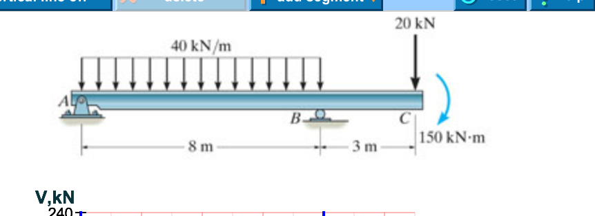
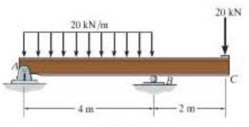
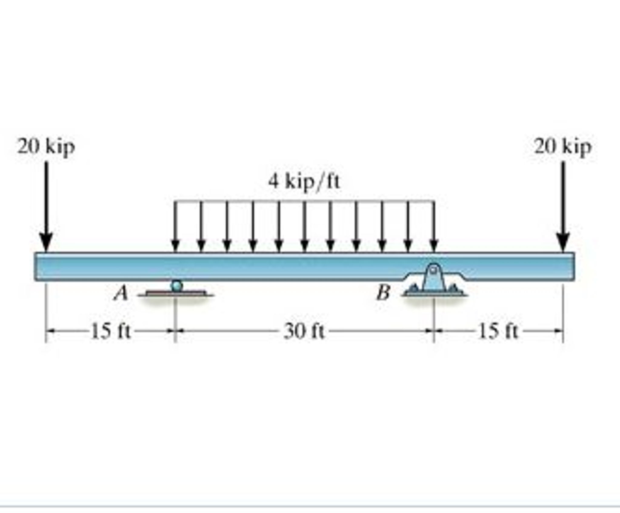
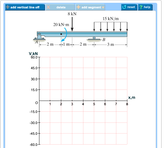
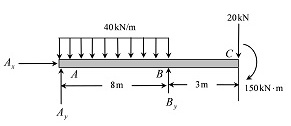
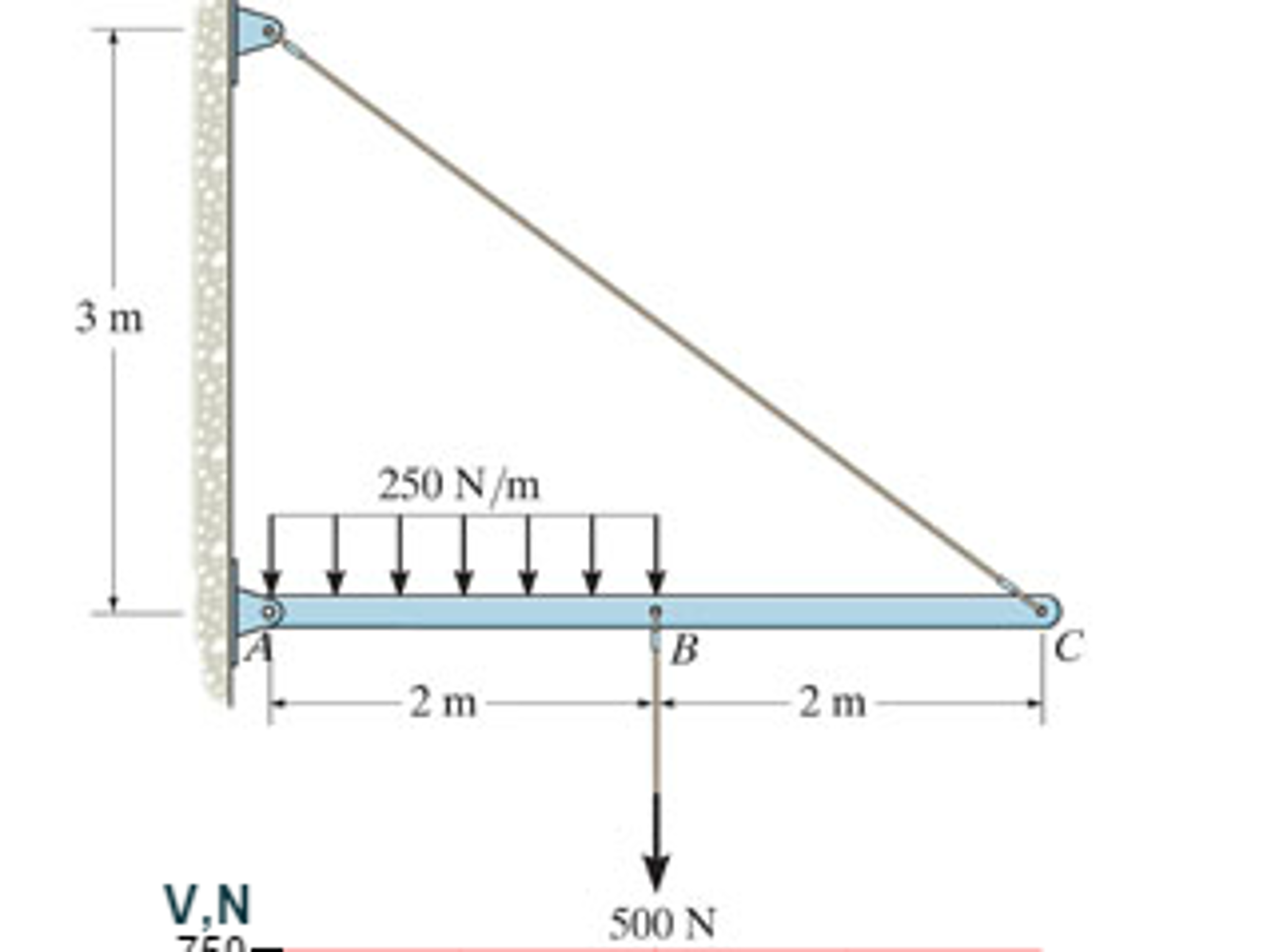
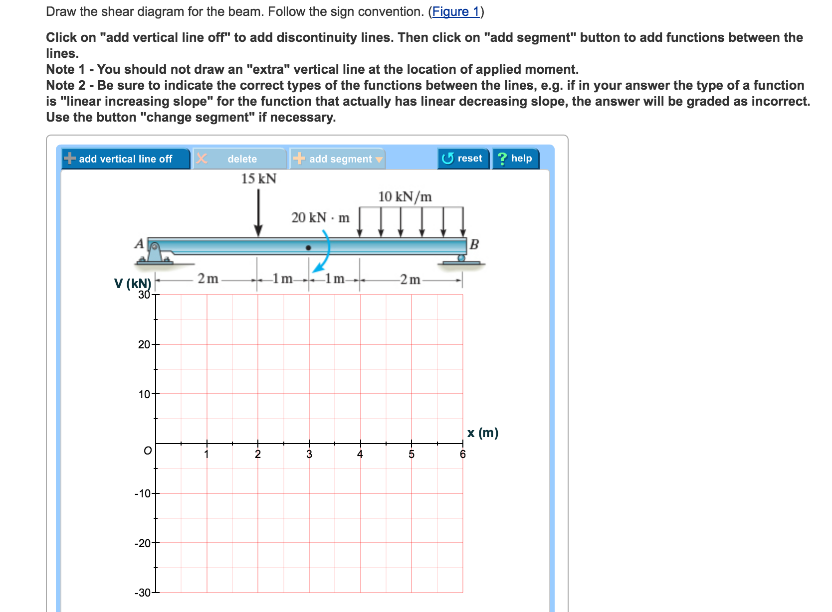
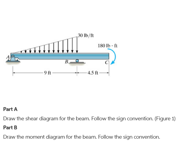
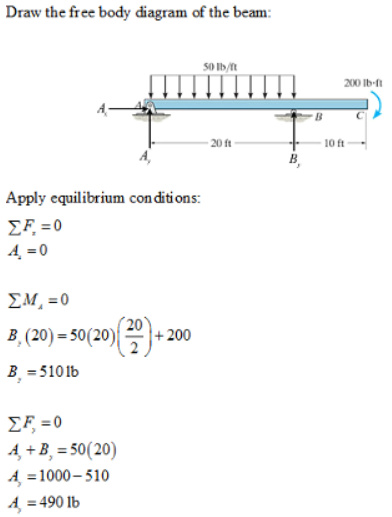
40 draw the shear diagram for the beam.
Shear Force and Bending Moment Diagram for a simply supported beam are as follows. Case 01. Simply supported beam with point load. Simply supported beam with point load. To find out Shear Force, first we will calculate R a and R c. Beam is simply supported ∑M a = ∑M c = 0. Let us consider ∑M a = 0. 6*4 - R c *8 = 0 (Clockwise bending ...
The shear diagram will plot out the internal shearing forces within a beam, or other body that is supporting multiple forces perpendicular to the length of the beam or body itself. The shear and moment diagrams are both used primarily in the analysis of horizontal beams in structures, such as floor joists, ceiling joists, and other horizontal ...
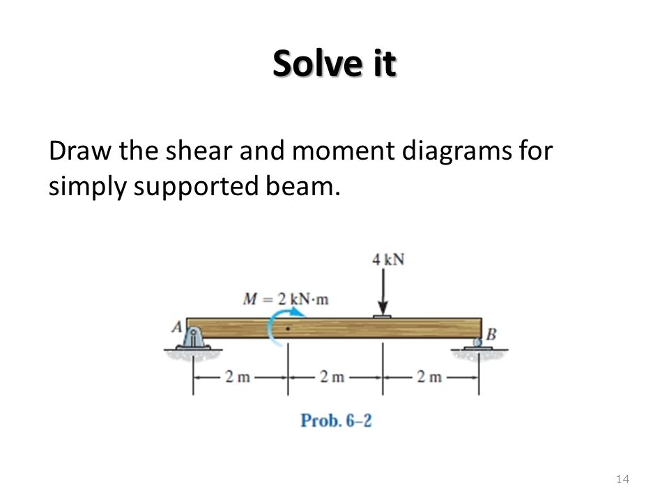
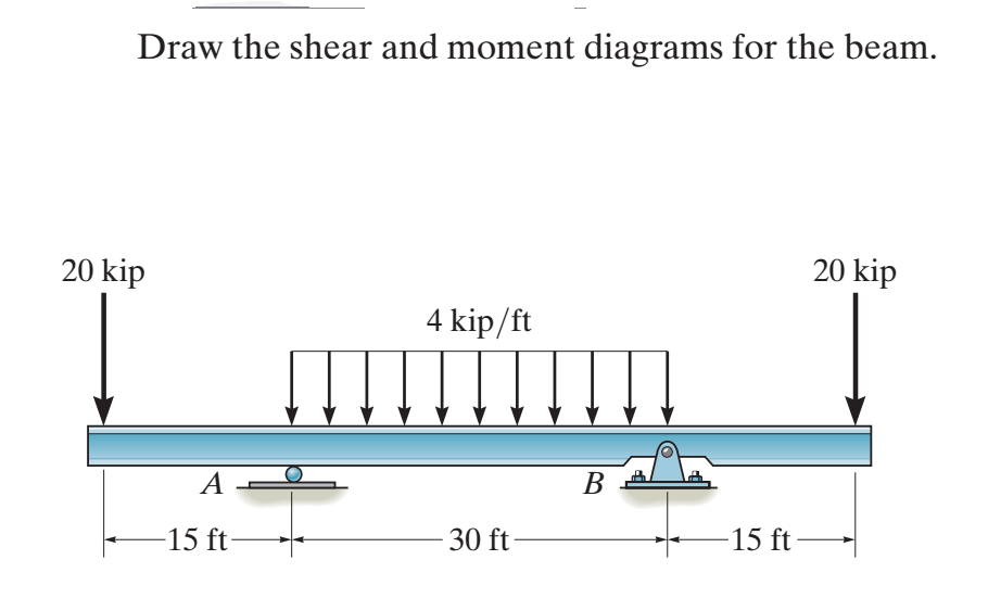
6 14 draw the shear and moment diagrams for the beam. 3. 5x} kip # ft,For 10 ft 6 x … 15 ft:V = - 0. Consider the forces to the left of a section at a distance x from the free end. — 1. 1) Under the shear diagram, drop vertical lines at every point of interest including every time the shear diagram crosses the axis, and at concentrated moments.
Draw the shear diagram for the beam.
Draw bending moment shear force shear and moment in beams the cantilever beam shown is subjected shear and moment in beams express the internal shear and moment. Solution to problem 403 shear and moment diagrams strength of le 1243 image text draw the shear and moment diagram for solved for the cantilever beam shown in figure below how to draw ...
Consider the free body diagram of the beams ABE and CBD of the beam separately and apply the force equilibrium equations to calculate the unknown support reactions at A, B, C and D.Consider a section between each segment of the beam and apply the equilibrium equations to calculate the shear force and bending moment at each location of the beam.
Draw the shear diagram for the beam. Click on "add discontinuity" to add discontinuity lines. Then click on "add segment" button to add functions between the lines. Part B. Draw the bending-moment diagram for the beam. Click on "add discontinuity" to add discontinuity lines. Then click on "add segment" button to add functions between the lines.
Draw the shear diagram for the beam..
Free online beam calculator for generating the reactions, calculating the deflection of a steel or wood beam, drawing the shear and moment diagrams for the beam. This is the free version of our full SkyCiv Beam Software. This can be accessed under any of our Paid Accounts, which also includes a full structural analysis software.
Draw the shear and moment diagrams for the beam, and determine the shear and moment throughout the beam as functions of x. Results. See All Results. Question: Mechanics of Materials - Instructor Solutions Manual [EXP-4667]
Draw the shear force and bending moment diagram for the beams shown below View Answer. Q: Draw the shear force and bending moment diagram for the beams shown below View Answer. Draw shear force and bending moment diagrams for the given simply supported beam. View Answer. The beam shown below has a sliding support at A and an elastic support ...
First draw the free-body-diagram of the beam with sufficient room under it for the shear and moment diagrams (if needed, solve for support reactions first). 2. Draw the shear diagram under the free-body-diagram. The distributed load is the slope of the shear diagram and each point load represents a jump in the shear diagram. Label all the loads ...
Q: Draw the cross-section effect diagrams (N, T, M) of the beam in Figure 1. Point B is the fixed suppo... A: To draw the cross section effects diagrams i.e. Normal force diagram Shear Diagram Moment diagram ...
Here are simple five steps applicable for drawing almost all types of shear force diagram correctly (Refer the following typical example in connection with the below steps): 1. Draw a horizontal line to represent the beam and divide the line by putting points at the following locations: - At the reaction locations.
Therefore the bending moment diagram is: Example 2 Draw the shear force and bending moment diagrams for the beam show below: a) determine the reactions at the supports Taking moments about A (clockwise moments = anti-clockwise moments) (10 x 6) x 3 = 6RC where 10 x 6 =60kN = total load and 3m =distance from A to where the load is acting. 6RC=180
Step 1. 1 of 7. In this task, we need to draw the shear and moment diagrams for the beam. Also, we need to determine the values of the bending moment at point. B B B. . Step 2. 2 of 7. Free body diagram.
Draw the Shear Force and Bending Moment diagrams and calculate the position and magnitude of the maximum B.M. (U.L.) The Total Load on the beam ( i.e. the load plus the mean rate of loading of 1/2 tons/ft) is given by:
Now, flip the beam horizontally 180º (or change the observation point, looking at the beam from the opposite side) and draw the diagrams, starting from the same point A. The diagrams will appear as follows: Note that, while the shear force diagrams appeared to be mirrored images (flipped horizontally), the bending moment diagram is not affected.
Axial Force, Shear Force and Bending Moment Diagrams for Plane Frames Previous definitions developed for shear forces and bending moments are valid for both beam and frame structures. However, application of these definitions, developed for a horizontal beam, to a frame structure will require some adjustments.
drawing the S/B diagrams. [1,2]The method of sections can be used to determine fully the shear force and bending moment at any cross-section of beams and to draw the S/B diagrams. When there are several external forces on a beam, the beam must be divided into several segments. The method of sections will be used repeatedly in each segment.
Draw the shear force and bending moment diagram for the beam. 12 KN 8 kN/m B 4 m 2 m. Being able to draw shear force diagram s (SFD) and bending moment diagram s (BMD) is a critical skill for any student studying statics, mechanics of materials, or structural engineering. There is a long way and a quick way to do them.
You will be fully competent in drawing shear force and bending moment diagrams for statically determinate beams and frames. You will have a robust system of analysis that allows you to confidently tackle the analysis of any statically determinate structure.
Begin the shear diagram by drawing a horizontal line, this is the line for zero shear. I like to draw my shear diagrams directly below the actual member so that they line up and I designate my shear diagrams with a big V. The beam is 20ft long divided into 5 foot sections.
section of a beam : draw a free-body diagram that expose these forces and then compute the forces using equilibrium equations. The goal of the beam analysis -determine the shear force Vand the bending moment Matevery cross section of the beam. To derive the expressions for Vand Min terms of the distance x measured along the beam.
.7—41. Draw the shear and moment diagrams for the simply supported beam. Since the loading discontinues at the 9- kN concentrated force, the shear and moment equations must be written for the regions O x < 4 m and 4 m < 6 m Of the beam. The free - body diagrams of the beam's segment sectioned through
Shear and Moment Diagrams Consider a simple beam shown of length L that carries a uniform load of w (N/m) throughout its length and is held in equilibrium by reactions R1 and R2. Assume that the beam is cut at point C a distance of x from he left support and the portion of the beam to the right of C be removed. The portion removed must then be replaced by vertical shearing
Steps to draw Shear force and Bending moment diagrams. In SFD and BMD diagrams Shear force or Bending moment represents the ordinates, and the Length of the beam represents the abscissa. Consider the left or the right portion of the section. Add the forces (including reactions) normal to the beam on the one of the portion.
Sections for Shear Force and Bending Moment Calculations: Shear force and bending moments are to be calculated at various sections of the beam to draw shear force and bending moment diagrams. These sections are generally considered on the beam where the magnitude of shear force and bending moments are changing abruptly.
Draw shear force and bending moment diagram of simply supported beam carrying uniform distributed load and point loads. As shown in figure. Solution First find reactions R1 and R2 of simply supported beam. Reactions will be equal. Since, beam is symmetrical. R1 = R2 = W/2 = (600 +600 + 200 x4)/2 = 1000kg Hence, R1 = R2 = 1000 kg. Shear Force
These instructions will help you to calculate and draw shear and bending moment diagram, as well as draw the resulting deflection. Knowing how to calculate and draw these diagrams are important for any engineer that deals with any type of structure because it is critical to know where large amounts of loads and bending are taking place on a beam so that you can make sure your structure can ...
Draw a diagram of the shear force in the beam. The shear in the end of the beam starts out at 0 lbs. However, since there is a reaction of 22,500 lbs on the left side of the beam, it will create that much shear in that location. The line load will cause this shear to decrease along the length











0 Response to "40 draw the shear diagram for the beam."
Post a Comment