41 limitorque l120 wiring diagram
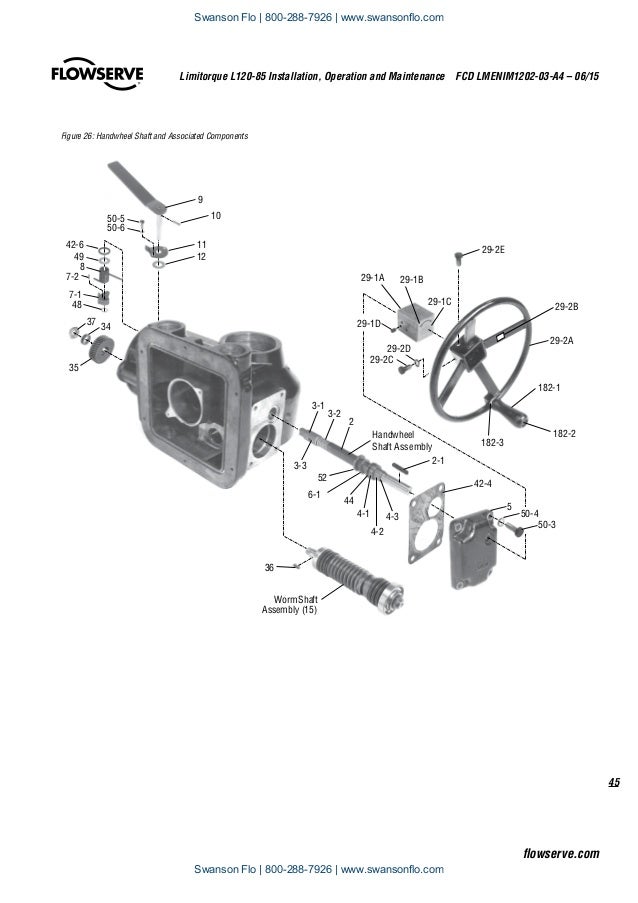
01.09.2018 01.09.2018 4 Comments on Limitorque L120-20 Wiring Diagram Limitorque Actuation Systems L Series FCD LMENIMA4 – 05/ 2 Declutch Assembly (L/40) (Refer to Figure ) . Verify all actuator wiring is in accordance with the applicable wiring diagram, national and local.
Limitorque Actuation Systems. Limitorque®. L120-190 through L120-2000. Installation and Maintenance Manual. FCD LMAIM1203-00. (Replaces 120-12000) ...
L120 NCU Wiring Diagram. *Title of each Drawing downloads the file. Drawing Number ...

Limitorque l120 wiring diagram
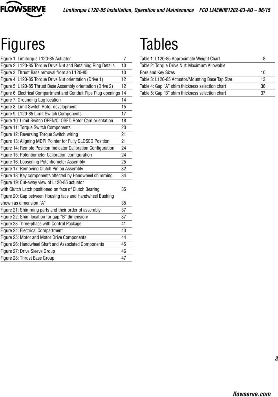
Limitorque ® L120-190 through L120-2000 ... Figure 8.2 – Wiring Diagram – Integral Controls 50 Figure 8.3 – Wiring Diagram – NCU 51 Tables Table 3.1 – Actuator Weights 10 Table 4.1 – Mounting Base Dimensions 13 Table 4.2 – Maximum Stem Acceptance 13
Limitorque L120 Wiring Diagram Collection. limitorque l120 wiring diagram - Exactly What's Wiring Diagram? A wiring diagram is a type of schematic which uses abstract photographic symbols to show all the affiliations of elements in a system. Wiring layouts are composed of two things: symbols that stand for the elements in the circuit, and also…
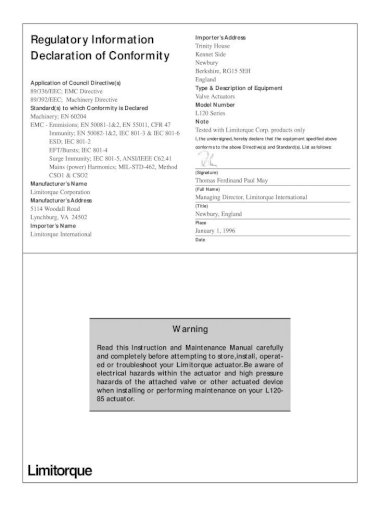
c WARNING: Read this Installation and Maintenance Manual carefully and completely before attempting to install, operate, or troubleshoot the Limitorque L120 ...76 pages
Limitorque l120 wiring diagram.
Limitorque Actuation Systems L120 Series FCD LMENIM1201-01 – 07/06 1 Introduction 1.1 Purpose This Installation and Maintenance Manual explains how to install and maintain the L120-10, L120-20, and L120-40 actuators. Information on installation, disassembly, reassembly, lubrication, and parts is provided. 1.2 User Safety
Limitorque® L120-190 through L120-2000 FCD LMENIM1203-01-A4 – 05/15 ... Figure 8.2 – Wiring Diagram – Integral Controls. 50. Figure 8.3 – Wiring Diagram – ...56 pages
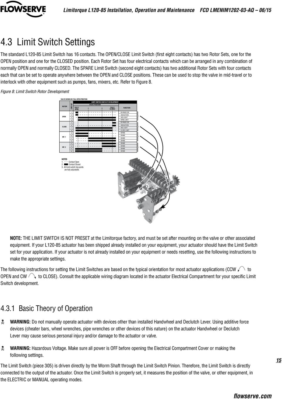
Consult the relevant wiring diagram for limit switch contact closed (Generally required if UEC-3 family (fig-2) development. All L120 units are supplied with 8 contact limit controller is supplied) switches-4 switches on each of 2 rotors. Two rotors are used A If contact is Normally Open (NO):-for end of travel indication.
Limitorque L120 Wiring Diagram. Limitorque Actuation Systems L Series FCD LMENIMA4 – 05/ 2 . Verify all actuator wiring is in accordance with the applicable wiring diagram. E September Limitorque L Series Installation & Maintenance Volt Torque Switch Figure – L through 40 typical wiring diagram Figure 5. ...
Limitorque Actuation Systems L120 Series FCD LMENIM1201-04-A4 – 03/18 flowserve.com. 5.2 Manual Operation. 20. 5.3 Motor Operation.36 pages
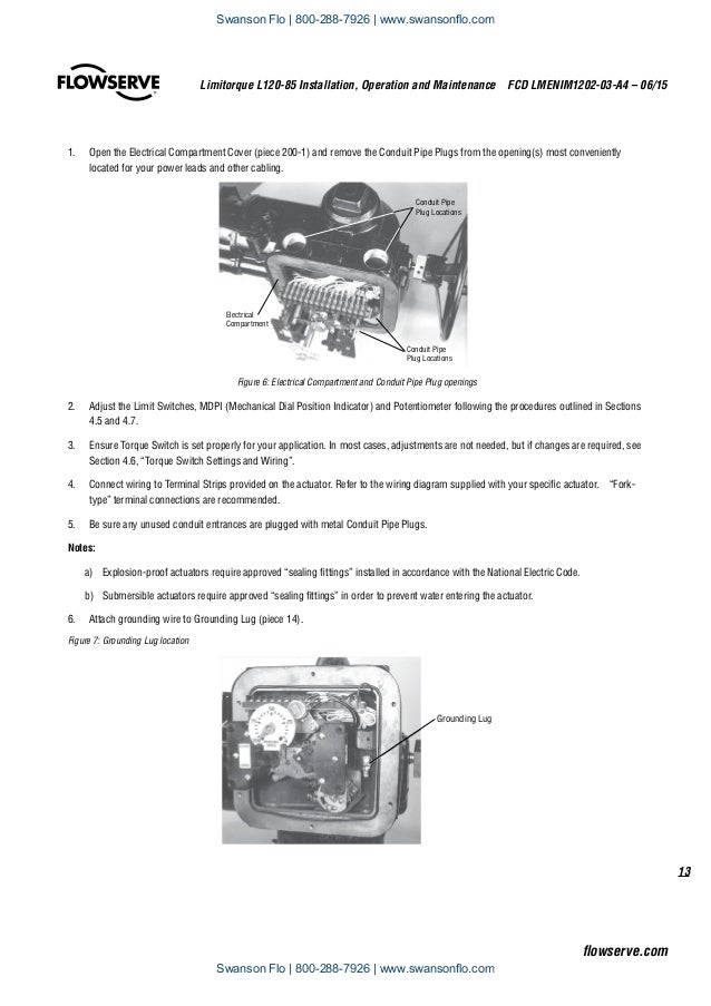
Refer to your actuator wiring diagram for user-specific wiring configuration. 4.2.3 Three-Phase Motor. 1. Using the Handwheel, move the valve to a midtravel ...52 pages
Drawing Type: MXa Wiring Diagram, QX Wiring Diagram. Then enter drawing number or select options. Drawing number: WD-MXa-. Remote Position Indication. .. Figure 1 - Limitorque L Actuator .. Refer to the wiring diagram on page 52 for reference and consult the applicable. Flowserve Limitorque L series multi-turn electric actuators have a solid .
L120 BIC Wiring Diagram. *Title of each Drawing downloads the file. Drawing Number. Description. Unit Size. 17-499-0005-3. 3ph Potentiometer. 17-499-0001-3. 3ph Potentiometer SW323.
Limitorque L120 Wiring Diagram 1 Wiring Diagram Source Limitorque Actuators Drawings Wiring Schematic Diagram Http Www Limitorqueindia Com Download Instruction And ...
stances, Limitorque’s L120 actuators are ideal for valves requiring rotary or linear movement. With nine unit sizes, L120 electric actuators make it easy to meet or exceed your requirements for positive, dependable valve actuation. Whether used with gate and globe valves, penstocks, or sluice gates, versatile L120 Series actuators operate without




![limitorque l120 - [PDF Document]](https://cdn.cupdf.com/img/1200x630/reader024/reader/2021010212/5695d51a1a28ab9b02a40f35/r-1.jpg)




0 Response to "41 limitorque l120 wiring diagram"
Post a Comment