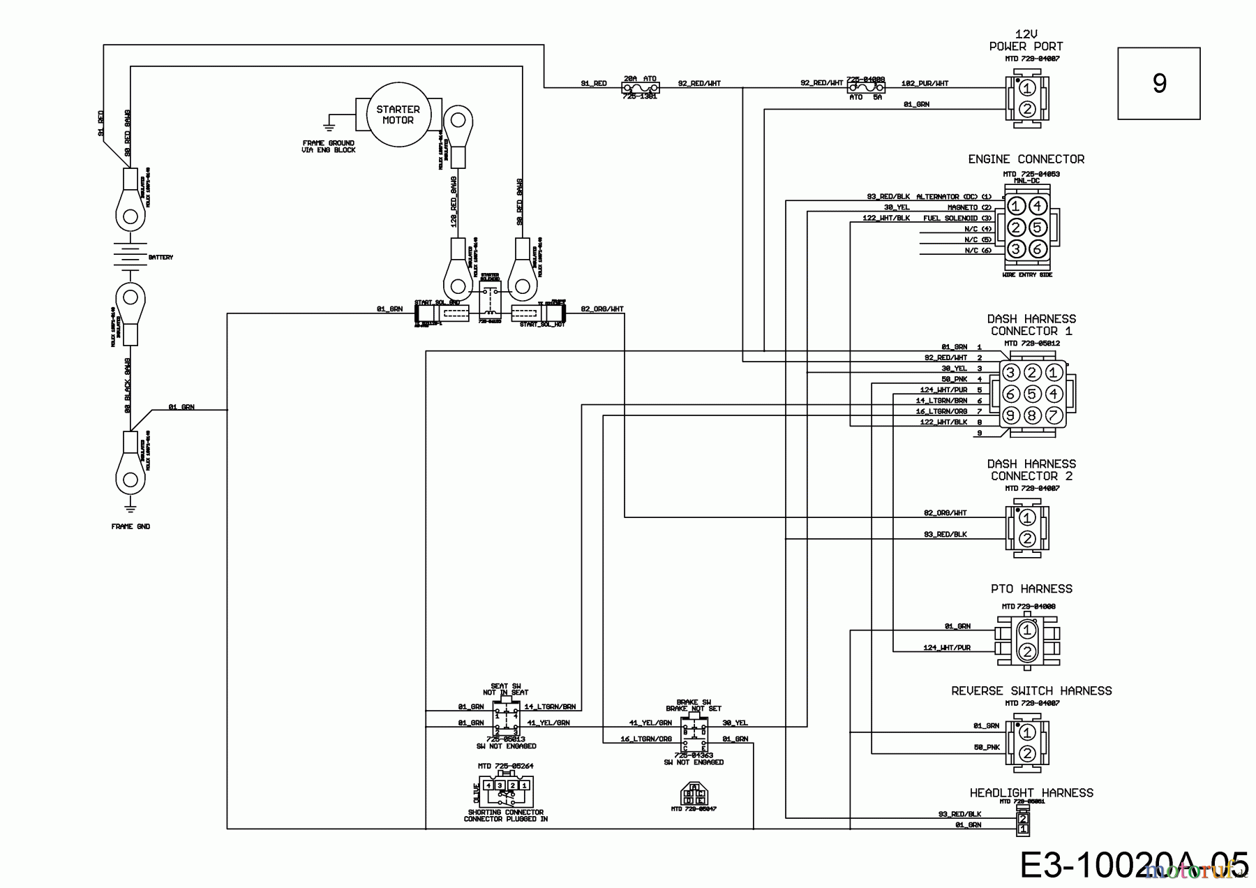
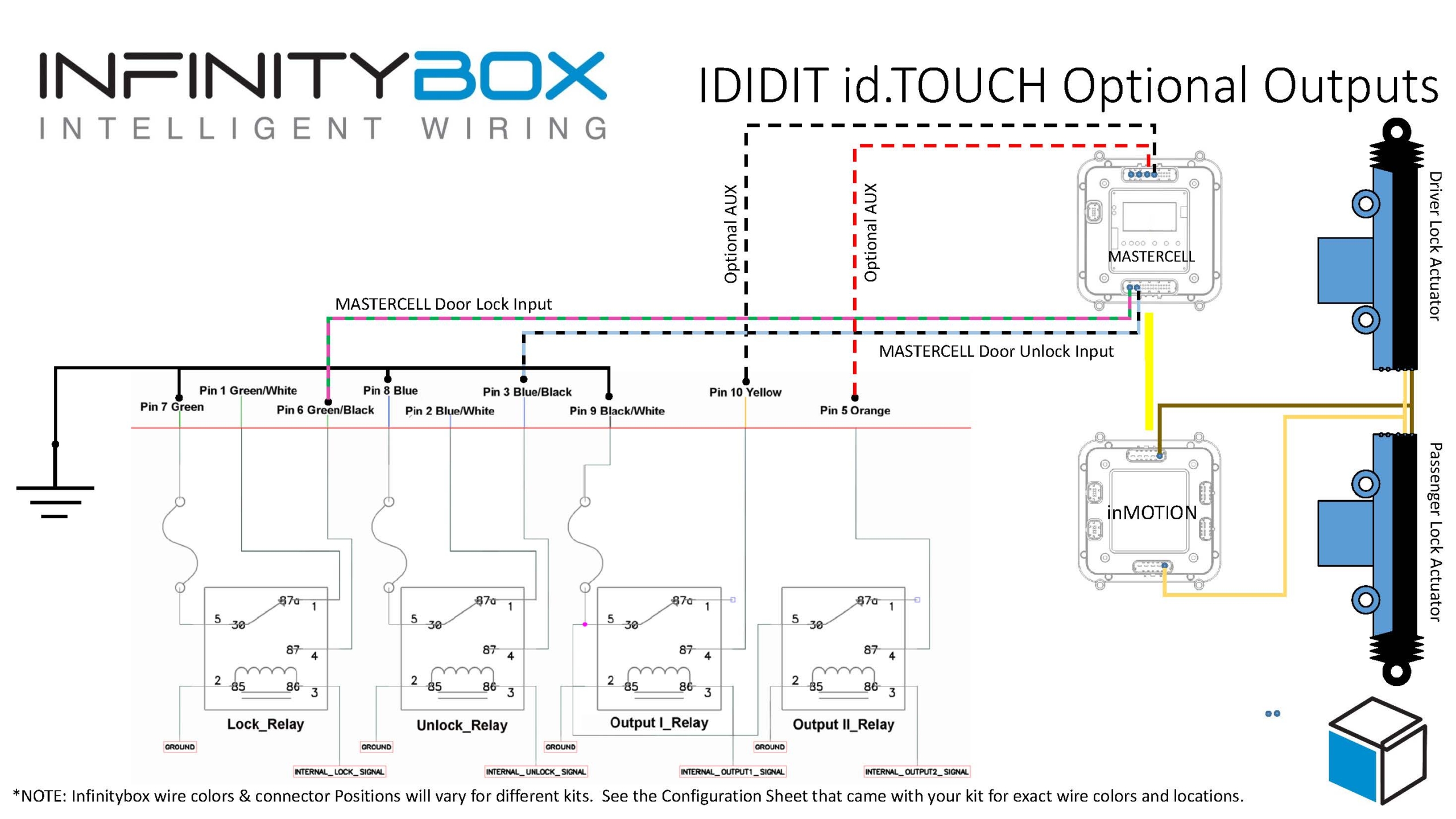
41 pbs 3 wiring diagram
Control wires were made from electrical wiring in unused portions of the castle. A glider expert, Lorne Welch, was asked to review the stress diagrams and calculations made by Goldfinch. The glider constructed was a lightweight, two-seater, high wing, monoplane design. It had a Mooney-style rudder and square elevators.
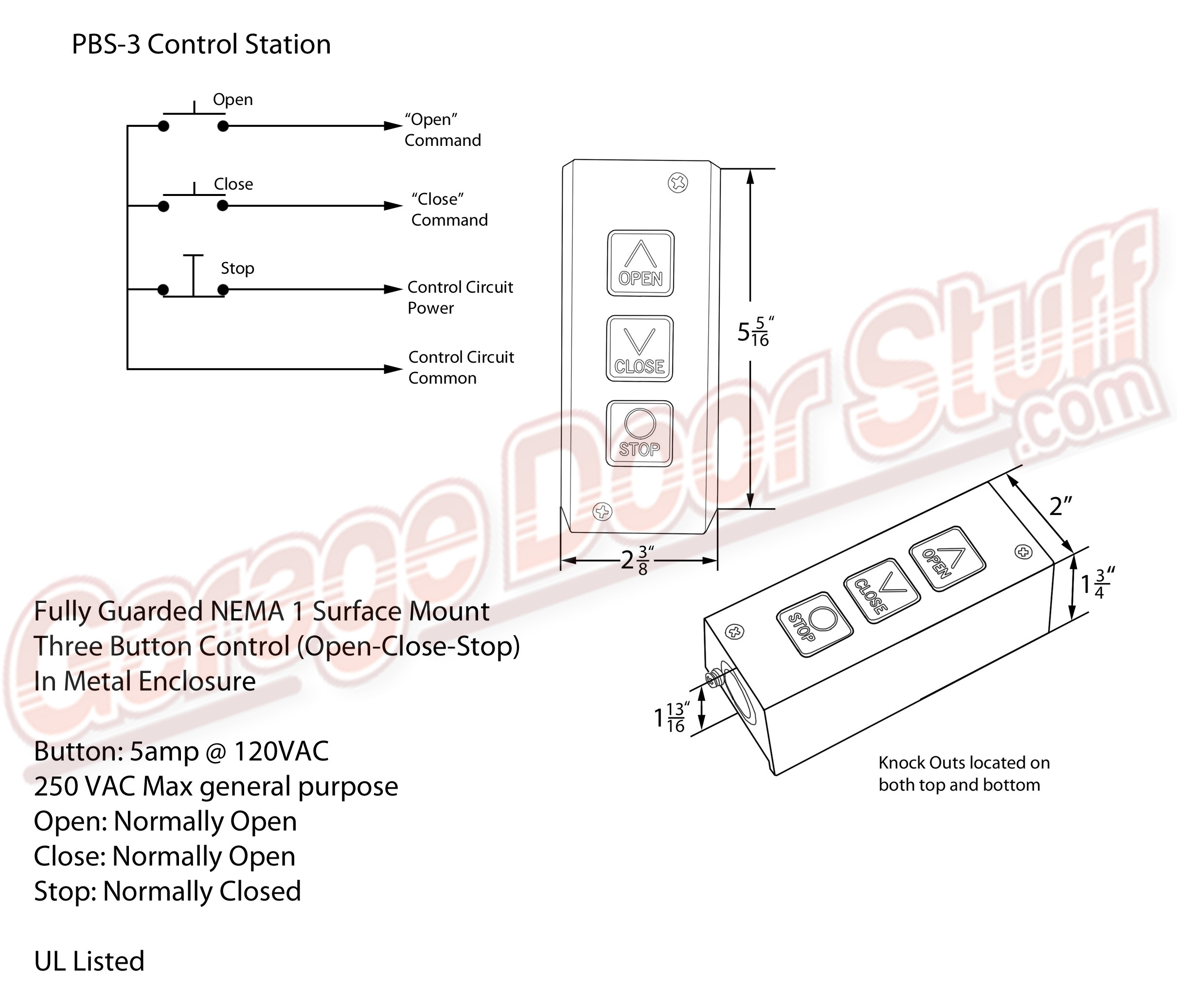
This control station is simple to install and can be used to operate a single gate or multiple gates or garage doors. Simply run wire (sold separately) to the ... Rating: 4.5 · 3 reviews · $58.01
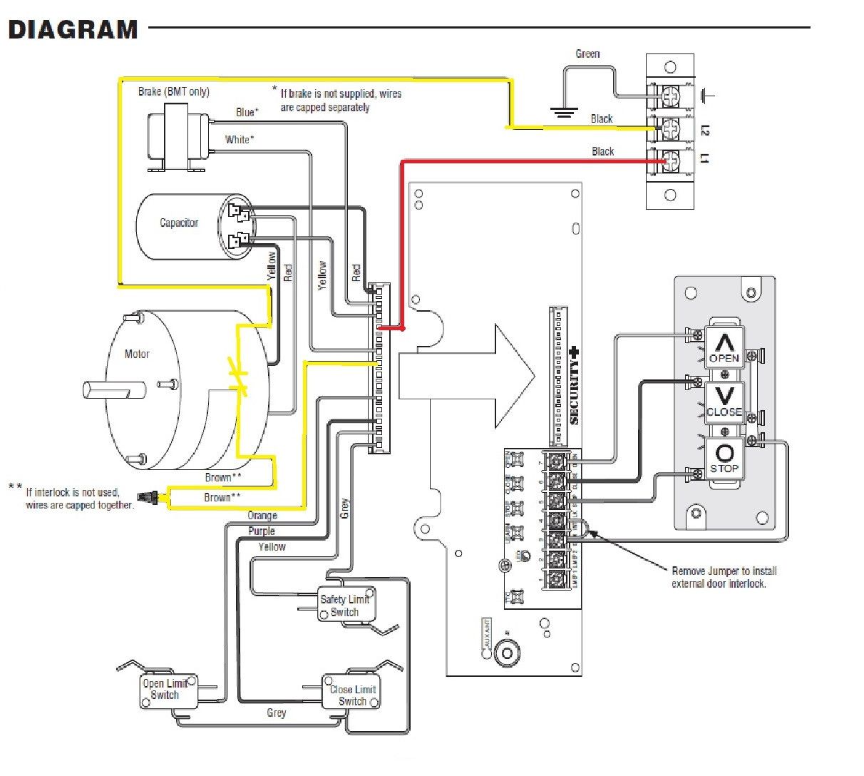
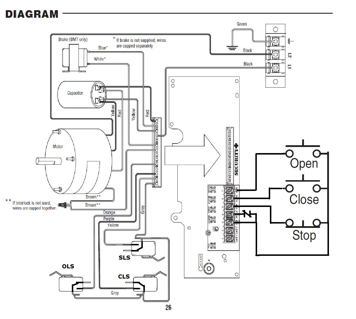
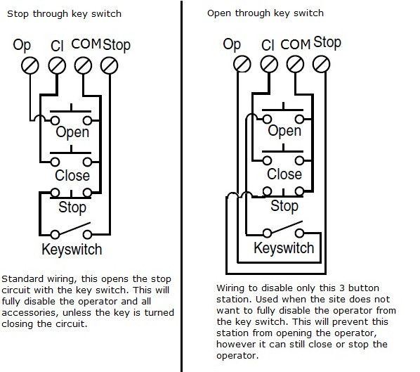
Wiring Schematic. Single 3-Button Station. Double 3-Button Stations. Multiple 3-Button Stations. Refer to the operator manual to verify wiring connections.1 page

Pbs 3 wiring diagram
3 Button Station / 1 Button Station / Interlock Wiring . ... appropriate terminals as per the wiring diagram and connect a ground wire to the grounding ...26 pages
SIMATIC S5 S5-115U Programmable Controller Manual CPU 941-7UB11 CPU 942-7UB11 CPU 943-7UB11 and CPU 943-7UB21 CPU 944-7UB11 and CPU 944-7UB21 EWA 4NEB 811 6130-02b
The open and close are normally open buttons. This did not work with my Viking gate that has the necessary 4 wires. I could open or close the gate but not stop ... Rating: 4.7 · 517 reviews
Pbs 3 wiring diagram.
This model features a durable, metal housing for enhanced safety and quality plus a momentary contact switch on the open, close and stop buttons. In addition to ... Rating: 5 · 2 reviews · $17.00 · In stock
PBS-3. Nema 1 Three Button Interior Surface Mount Control Station. Momentary Contact, OPEN-CLOSE-STOP H=5-5/16" W=2-3/8" D=1-13/16" with Metal Housing.
Jun 24, 2021 · 2011 Ford F150 Fuse Diagram for Power Distribution Box. 1 Powertrain control module (PCM) relay (3.7L, 5.0L and 6.2L engines) 2 Starter relay 3 Blower motor relay 4 Rear window defroster relay 5 Electric fan relay (high speed) 6 Trailer tow (TT) park lamp relay 7 Run/start relay 8 Fuel pump relay 9 TT Battery charger relay 10 PCM relay (3.5L ...
Jun 19, 2020 · Working voltage: DC3.3-5V; Photoresistor Model: 5516; Module pins: 3-pin or 4-pin (an additional analog output AO for 4-pin) Common circuit diagram (3)Photoresistor application circuit diagram. The following figure is a schematic diagram of the application of the photoresistor in the light control switch.
Secret Sessions Lisa Gcrusy from pbs.twimg.com Julia sessions 24 set star. Find the latest breaking news and information on the top stories, weather, business, entertainment, politics, and more. Secret session lisa photos full hd4k videos.
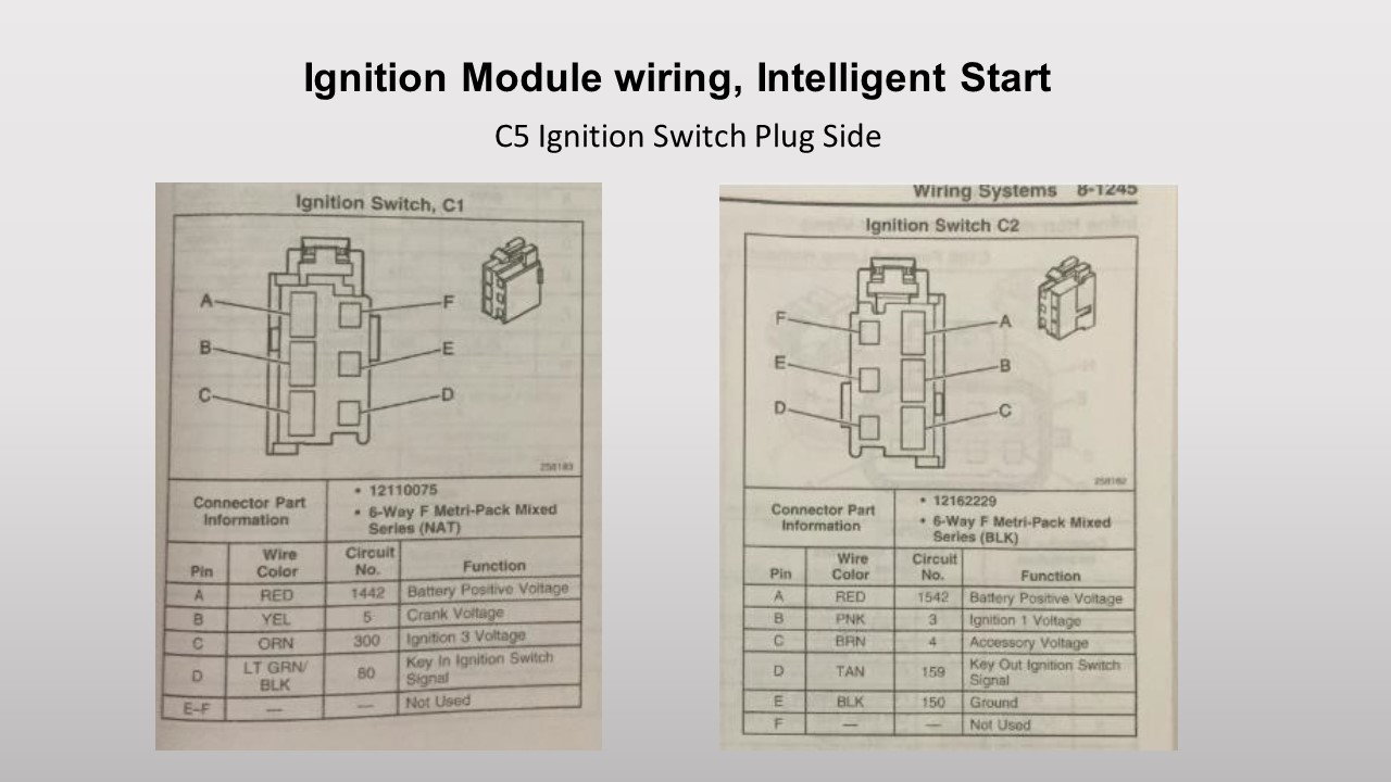
Wiring Diagram Pictures Detail: Name: 3 position ignition switch wiring diagram – When turned to the 2nd position ignition terminals 2 5 and 3 white. PDF Catalogs. M. Get link. It will have 3 wires running into it from the harness, 2 from the distributor and 1 spark plug wire.
Control Stations. 3-Button Indoor Surface Mount Station. NEMA 1 steel enclosure, indoor surface-mount installation. Installation and wiring instructions can ...
Wiring the Holley Dominator EFI: Wiring the Holley Terminator EFI: FAST EZ-EFI Wiring: FAST XFI 2.0 EFI Wiring: MSD Atomic EFI: Speartech LS-58X Engine Wiring: Wiring Diagram for AEM Infinity ECU: Wiring Diagram for Holley Sniper EFI System: Wiring Diagram for FiTech Go EFI: Wiring Diagram for MS3Pro EVO ECU: Wiring Diagram for VaporWorx Fuel ...





.jpg)







0 Response to "41 pbs 3 wiring diagram"
Post a Comment