41 shear and moment diagram examples
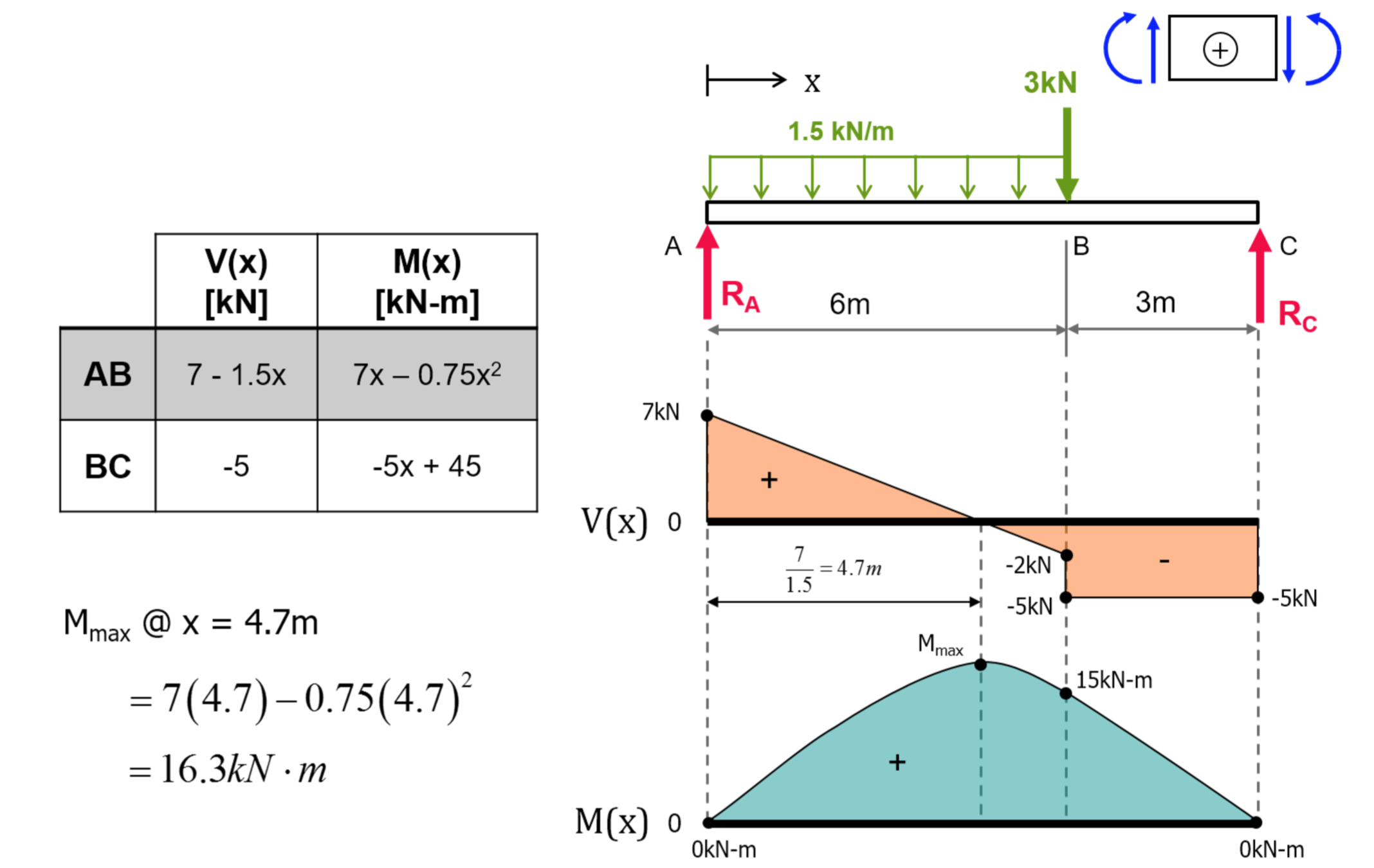
Basic Example to Construct a Shear and Moment Diagram : Constructing shear and moment diagrams is similar to finding the shear and moment at a particular point on a beam structure. However, instead of using an exact location, the location is a variable distance 'x'. This allows the shear and moment to be a function of the distance, x.
Examples: Level 1: Single Point Load. This is example shows how to use the steps outlined in the "Steps" tab to draw shear force and bending moment diagrams. Level 2: Distributed Force. This example deals with a constant distributed force (shear is a linear function of x). Level 3: Point Moment. In this example, the point moment causes no shear ...
As you encounter changes in the shear diagram, draw the moment diagram as outlined in Note B. Label magnitude of the moment at the maximum and minimum points along the function as well as what point along the X axis they occur. Note A. A point load (a force at a single point) causes the shear diagram to jump straight up or down; up if the load is pushing up and down if the force is pushing ...

Shear and moment diagram examples
❑The weight of the beam is an example of distributed loading, but ... 4.3 Shear- Moment Equations and Shear-Moment Diagrams. ❑ The determination of the ...42 pages
the shear and bending moment diagrams. 7 V and M are in the opposite directions of the positive beam sign convention. 8 Shear and Bending Moment Diagrams Zero Shear. Maximum. Positive. Bending. Moment ⇒ 9 Principle of Superposition. 10 Example Problem Shear and Moment Diagrams Calculate and draw the shear force and bending moment equations ...
Example: Draw the shear and moment diagrams for the following beam using superposition. 10 ft. A 5 k/ft. 10 k 10 ft. Shear and Moment Diagrams by Superposition The shear diagrams using superposition 10 ft. A 5 k/ft. 10 k 10 ft. 5 k/ft. + 10 k x V (k) 50 x V (k) 10 x V (k) 60 10 Shear and Moment Diagrams
Shear and moment diagram examples.
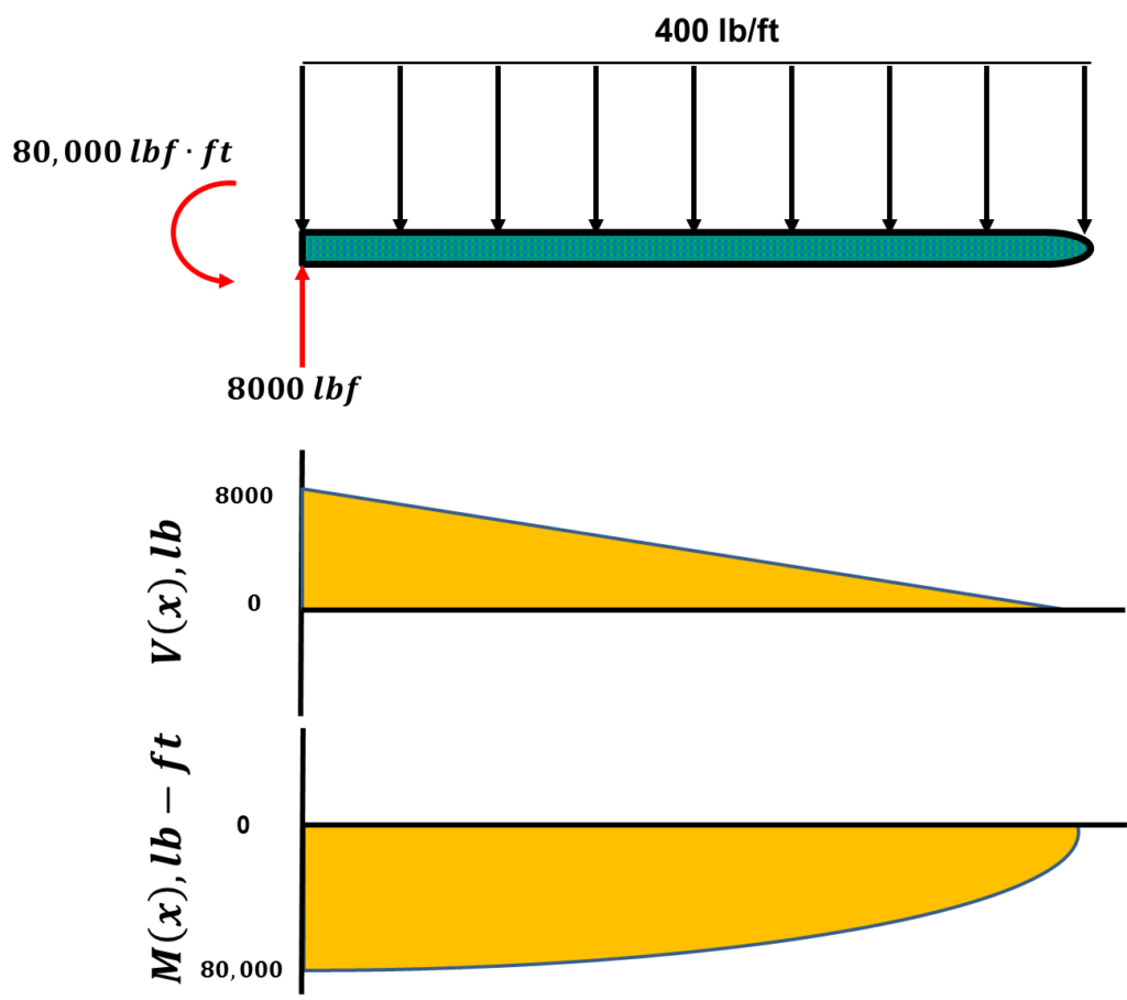
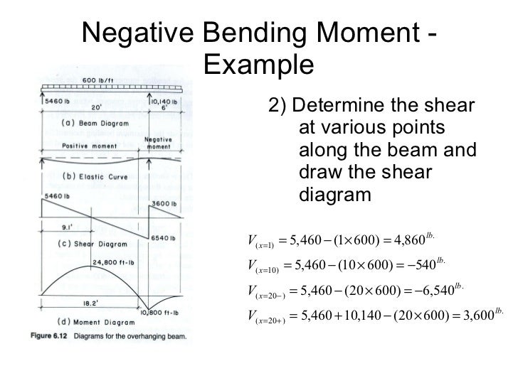
The equation also suggests that the slope of the moment diagram at a particular point is equal to the shear force at that same point. Equation 6.1 suggests the following expression: ΔM = ∫ V (x)dx Δ M = ∫ V ( x) d x (Equation 6.2) Equation 6.2 states that the change in moment equals the area under the shear diagram.
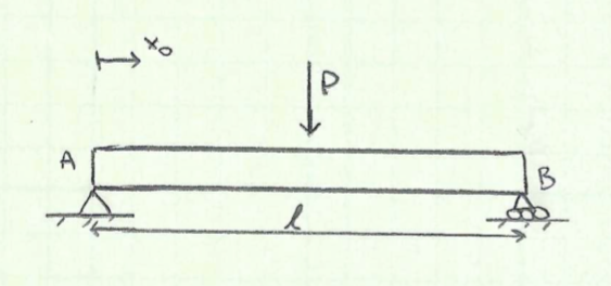
Shear and Moment Diagrams Consider a simple beam shown of length L that carries a uniform load of w (N/m) throughout its length and is held in equilibrium by reactions R1 and R2. Assume that the beam is cut at point C a distance of x from he left support and the portion of the beam to the right of C be removed. The portion removed must then be replaced by vertical shearing
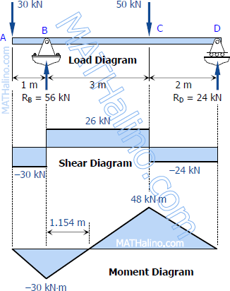
Draw the shear and moment diagrams for the beam. Indicate values at the supports and at the points where a change in load occurs.
2 LECTURE 13. BEAMS: SHEAR AND MOMENT DIAGRAMS (GRAPHICAL) (5.3) Slide No. 2 ENES 220 ©Assakkaf Example 8 (cont'd) A free-body diagram for the beam is shown Fig. 17. The reactions shown on the
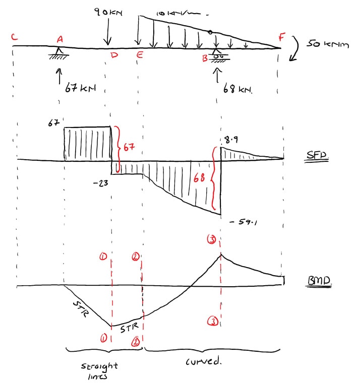
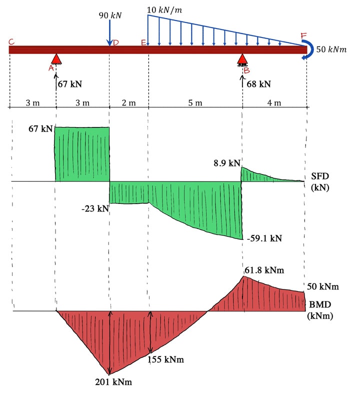
Consider the shear force between A and D for example; it’s constant, which means the slope of the bending moment diagram is also constant (an inclined straight line). Between D and E, the shear force is still constant but has changed sign. This tells us the slope of the bending moment diagram has also changed sign, i.e. the bending moment diagram has a local peak at D.
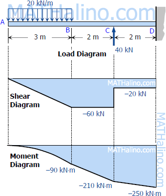
Shear Diagram. Moment Diagram. 1. Point loads cause a vertical jump in the shear diagram. The direction of the jump is the same as the sign of the point load. 2. Udl result in a straight, sloped line on the shear diagram. 3. The shear diagram is horizontal for distances along the beam with no applied load.
Shear and Moment Diagrams Diagrams. As an alternative to splitting a body in half and performing an equilibrium analysis to find the internal forces and moments, we can also use graphical approaches to plot out these internal forces and moments over the length of the body. Where equilibrium analysis is the most straightforward approach to finding the internal forces and moments at one cross ...
Shear Diagram : Recall, the shear is the derivative of the moment, dM/dx = V, and thus the moment will be a maximum (or minimum) when the shear is 0. From the shear diagram it is noticed that the shear is zero at x = 0.5 ft and x = 1.5 ft. At those points, the moment is -40 ft-lb (x = 0.5) and 20 ft-lb (x = 1.5).
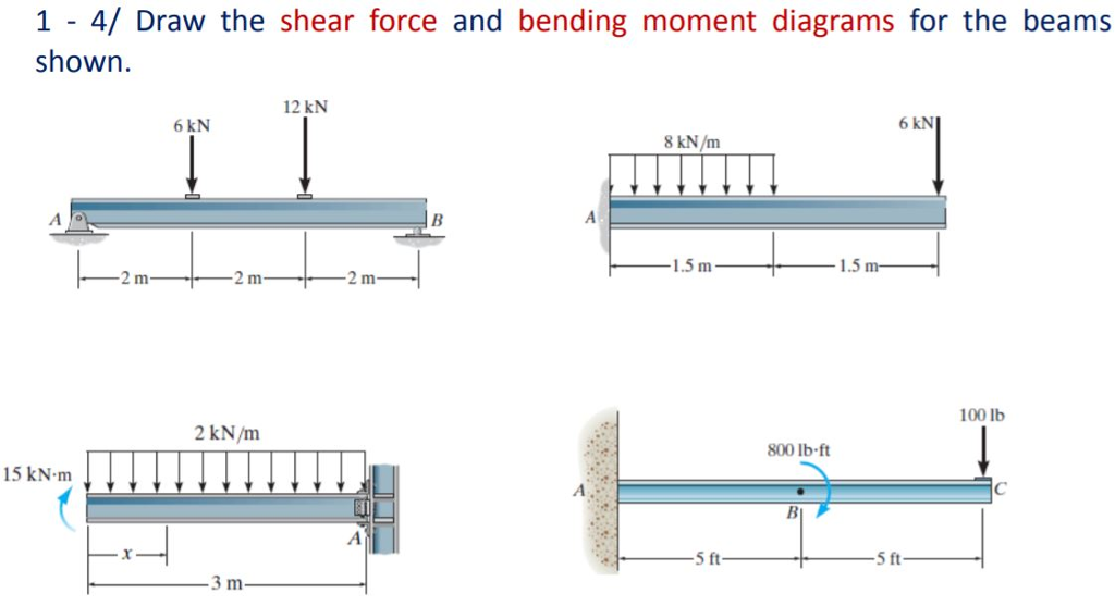
Problem 403 Beam loaded as shown in Fig. P-403. [collapse collapsed title="Click here to read or hide the general instruction"]Write shear and moment equations for the beams in the following problems. In each problem, let x be the distance measured from left end of the beam. Also, draw shear and moment diagrams, specifying values at all change of loading positions and at
CE 331, Fall 2007 Shear & Moment Diagrams Examples 3 / 7 max MD = 16.0k-ft at Support 2 3. Calculate the max. moment due to live load (ML) at the location of the max. moment due to dead load (MD). 3.1 Determine where to place the live load to cause the max ML at the middle of Span 1. As mentioned on Page 1, the location of live loads is variable.
this is a detailed example of shear and moment diagrams, i recommend skipping around to the sections shown below if you already have a feel for the subject:i...
Lesson 12: Drawing Shear and Moment Diagrams Example- Mechanics of Materials and Statics. This is a detailed example of shear and moment diagrams. Lessons. Lesson 1: Statically Indeterminate Explanation – Structural Analysis; Lesson 2: Is it statically indeterminate? Examples – Structural Analysis ; Lesson 3: Calculating Reactions for Beam with Hinge – Statics/Mechanics Example; Lesson 4 ...
Example of drawing a shear and moment diagram graphically for a simply supported beam with a concentrated moment and linearly distributed load. I recommend ...
PDF_C8_b (Shear Forces and Bending Moments in Beams) Q6: A simply supported beam with a triangularly distributed downward load is shown in Fig. Calculate reaction; draw shear force diagram; find location of V=0; calculate maximum moment, and draw the moment diagram. 6k/ft 9 ft RA = (27k)(9-6)/9= 9k A B F = (0.5x6x9) = 27k x = (2/3)(9) = 6 ft
Being able to draw shear force diagrams (SFD) and bending moment diagrams (BMD) is a critical skill for any student studying statics, mechanics of materials, or structural engineering. There is a long way and a quick way to do them. The long way is more comprehensive, and generates expressions for internal shear and internal bending moment in terms of x: V(x) and M(x), respectively. This is ...
Shear and Moment Diagrams If the variation of V and M are written as functions of position, x, and plotted, the resulting graphs are called the shear diagram and the moment diagram. Developing the shear and moment functions for complex beams can be quite tedious.
















0 Response to "41 shear and moment diagram examples"
Post a Comment