41 stress strain diagram steel
The stress-strain diagram provides a graphical measurement of the strength and elasticity of the material. Also, the behaviour of the materials can be studied with the help of the stress-strain diagram, which makes it easy with the application of these materials. What is the relation between stress and strain?
the stress-strain curve and a straight line with slope of E and beginning at 0.002 (0.2%) on the strain axis. The most satisfactory definition of yield strength for aluminum alloys and many other materials. Note: At this definition of yield, the plastic portion of the strain is 0.002 and the elastic portion of the strain is . σ y σ σ y E E 1 ...
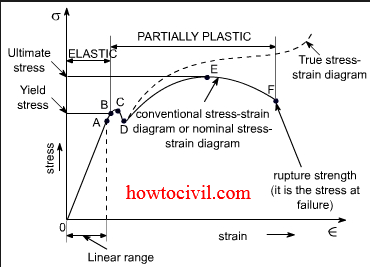
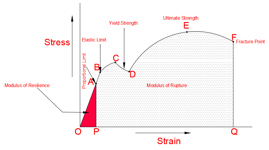
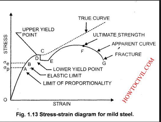
The diagram below shows the stress strain diagram for a typical ductile steel. The important points on this graph are identified as follows. The stress strain relationship is a straight line between 0 and A . Within this region if the load is removed the specimen would return to its original length.
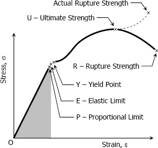
Stress strain diagram steel
The entire process is plotted in a curve and the same is known as stress-strain curve of steel. Stress-strain curve of materials Stress strain curve of steel, aluminum, cast iron, elastomers etc., are described. Stress Strain Curve for Steel Curve Refer to below diagram for stress strain curve of steel. Stress Strain Curve for Steel
The stress-strain diagram is also used to determine the static load capacity of spring steel. The stress-strain diagram shows the strain behaviour of the spring steel up to fracture during the tensile test. For the designer, the stress-strain diagram is an important design specification, as he can read off from this diagram how much force the ...
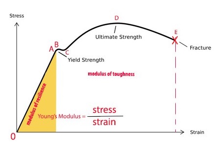
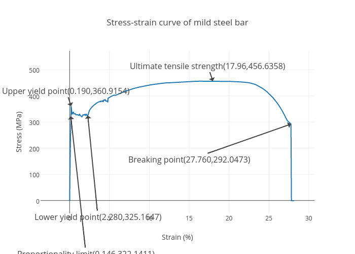
Value of stress correspond to peak point on stress strain curve for mild steel is the ultimate stress. It is denoted by point E in diagram. Breaking stress Point on the stress strain curve where material fails, is known as breaking point. Stress correspond to this point is known as breaking stress. Summary
Stress strain diagram steel.
G ⇒Shear Modulus- Slope of the initial linear portion of the shear stress-strain diagram. G (Steel) ≈ 12 x 106psi G (Aluminum) ≈ 4 x 10⁶psi Percent Elongation- The strain at fracture in tension, expressed as a percentage = ((final gage length - initial gage length)/ initial gage length) x 100. Percent elongation is a measure of ductility.
the load, we can plot a diagram of stress versus strain Stress-strain diagrams were originated by: Jacob Bernoulli (1654-1705) and J. V. Poncelet (1788- 1867) Developing a Stress-Strain Diagram Stress-Strain for Steel The first material we will discuss is: structural steel A stress-strain diagram for a typical structural steel in
Alloy steel stress-strain diagram. The engineering tension test is widely used to provide basic design information on the strength of materials and as an acceptance test for the specification of materials. In the tension test a specimen is subjected to a continually increasing uniaxial tensile force while simultaneous observations are made of ...
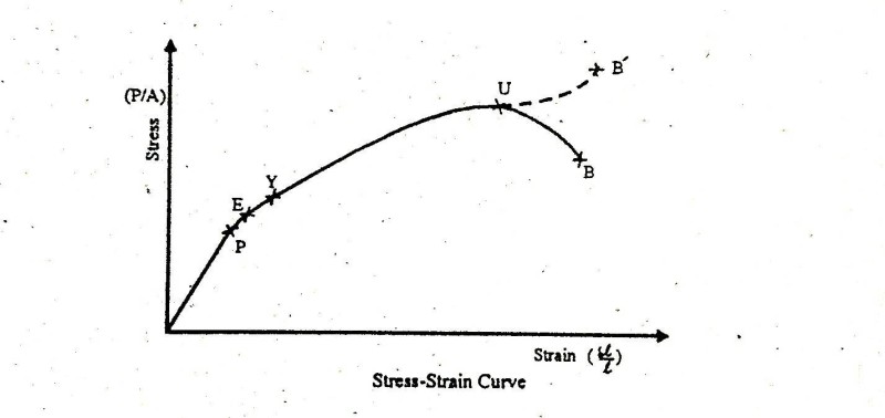
1. sketch stress-strain curve (S) 2. identify proportional limit, elastic limit and yield point (S) 3. predict ultimate tensile strength and breaking stress(S) 4. list four uses of stress-strain diagram (T) 5. identify ductile and brittle regions from stress-strain curve (E)
When steel is curved, it is important to keep the stress-strain curve ratio for mild steel in mind. Below is a stress-strain graph that reviews the properties of steel in detail. If tensile force is applied to a steel bar, it will have some elongation. If the force is small enough, the ratio of the stress and strain will remain proportional.
The formula that is used for the calculation of stress and strain are Where, σ = stress P = Load e = strain dL = extension produced in the rod L = original length A = cross section area We plot a graph between the stress and strain and a curve is obtained. This curve so obtained is called the stress strain curve or stress strain diagram.
STRESS-STRAIN CURVES David Roylance Department of Materials Science and Engineering Massachusetts Institute of Technology Cambridge, MA 02139 August 23, 2001
Stress-Strain Diagrams of Steel. version 1.0.1 (1.9 KB) by Ayad Al-Rumaithi. Calculates stress value of steel given strain and material properties . 5.0 (1) 185 Downloads. Updated 06 Jun 2019. View Version History. × Version History. Download. 6 Jun 2019 ...
The above image shows the stress-strain diagram of mild steel. There are many different points or regions located on the stress-strain diagram explain below 1. Proportional limit 2. Elastic limit 3. Yield point · Upper Yield point · Lower Yield point 4. Ultimate point 5. Fracture point Proportional limit
STRESS-STRAIN DIAGRAM: The mechanical properties of a material are determined in the laboratory by performing test on the small specimens of the material. Most common material test is the Tension Test. In this test, loads are measured on the main dial of the machine while the elongations are measured with the help of extensometers.
Academia.edu is a platform for academics to share research papers.
stress-strain diagram for Copper. You may watch this video for gathering the best knowledge of it . If You have any Questions Please comments below! please share stress-strain curve for mild steel and concrete and copper. thanks. Researchgate.
Some examples of ductile materials are aluminum, mild steel and some of its alloys i.e. copper, magnesium, brass, nickel, bronze and many others. Stress Strain Diagram For Ductile Material: We have taken annealed mild steel as a ductile material. Different Points On Stress Strain Curve:
In this experiment we will look at the stress-strain behavior of two types of steel that bound the range usually seen in civil engineering applications - from a very mild, hot rolled steel to a hard, cold rolled one. Principles The term steel is commonly used to denote a material that is principally iron (Fe), often in the 95% to 98% range.
As shown below in the stress strain curve. From the diagram one can see the different mark points on the curve. It is because, when a ductile material like mild steel is subjected to tensile test, then it passes various stages before fracture. These stages are; Proportional Limit Elastic Limit Yield Point Ultimate Stress Point Breaking Point
A schematic diagram for the stress-strain curve of low carbon steel at room temperature is shown in figure 1. There are several stages showing different behaviors, which suggests different mechanical properties. To clarify, materials can miss one or more stages shown in figure 1, or have totally different stages.
The Figure 7.1 shows the stress-strain diagram for mild steel. The elastic limit, upper yield point, lower yield point and proportional limit are represented by (a) A, B, C, D (b) A, C, D, B (c) B, C, D, A (d) C, B, D, A (e) B, C, A, D 8.
The stress strain diagram for mild steel and. Stress strain curve is a behavior of material when it is subjected to load. The rod in the example above is 2 m long and made of steel with modulus of elasticity 200 gpa 200 10 9 nm 2. Welcome to howtocivil. There are several stages showing different behaviors which suggests different mechanical ...
Stress vs. strain relationship Structural analysis and design requires understanding of the system of the applied forces and the material behavior The behavior of a material can be studied by means of mechanical testing Stress vs. strain diagrams are often used to describe the material behavior Stress vs. strain diagrams are supposedly ...
Ramberg-Osgood Equation The stress-strain curve is approximated using the Ramberg-Osgood equation, which calculates the total strain (elastic and plastic) as a function of stress: . where σ is the value of stress, E is the elastic modulus of the material, S ty is the tensile yield strength of the material, and n is the strain hardening exponent of the material which can be calculated based on ...
The graph of these quantities with the stress σ along the y-axis and the strain ε along the x-axis is called the stress-strain diagram. The stress-strain diagram differs in form for various materials. The diagram shown below is that for a medium-carbon structural steel.
Strain. Strain is the change in the dimension (L-L 0) with respect to the original. It is denoted by the symbol epsilon (ε). The formula is ε = (L-L 0) / L 0. For a shear force, strain is expressed by γ (gamma) From the origin O to the point called proportional limit, the stress-strain curve is a straight line.
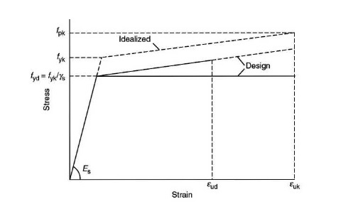
The stress-strain curve describes the behavior of steel bars under loads. It is created by testing steel specimens. A steel specimen is gradually pulled through a testing machine until it breaks, and stress and corresponding strains are recorded.
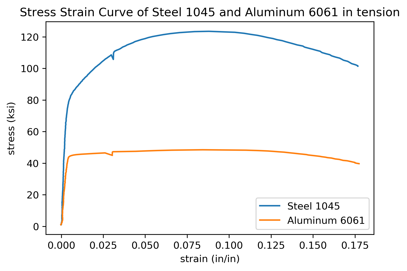
The stress-strain curves of an AISI 1008 steel. The steel is not highly ductile. Even in the annealed condition, the fracture occurred at a strain of 0.18. The stress-strain curve following the 58.5% cold reduction exhibits the yield point extension. View chapter Purchase book Raw materials for terry fabrics













0 Response to "41 stress strain diagram steel"
Post a Comment