42 bending moment diagram examples
Being able to draw shear force diagrams (SFD) and bending moment diagrams (BMD) is a critical skill for any student studying statics, mechanics of materials, or structural engineering. There is a long way and a quick way to do them.
Technical Background. As a methods of structural analysis, the matrix stiffness method is particularly suited for computer-automated analysis of complex structures including the statically indeterminate type.
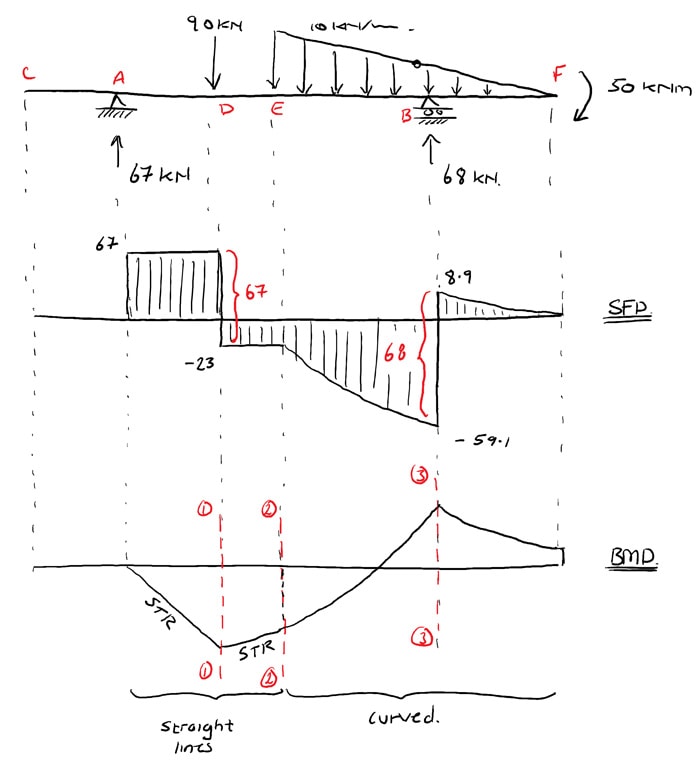
Once you have the reactions, draw your Free Body Diagram and Shear Force Diagram underneath the beam. Finally calculating the moments can be done in the following steps: 2. From left to right, make “cuts” before and after each reaction/load. To calculate the bending moment of a beam, we must work in the same way we did for the Shear Force ...
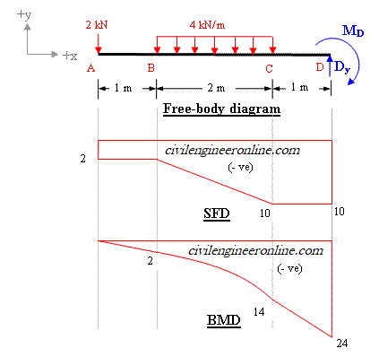
Bending moment diagram examples
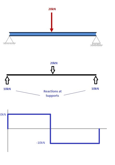
Examples: Level 1: Single Point Load. This is example shows how to use the steps outlined in the "Steps" tab to draw shear force and bending moment diagrams. Level 2: Distributed Force. This example deals with a constant distributed force (shear is a linear function of x). Level 3: Point Moment. In this example, the point moment causes no shear ...
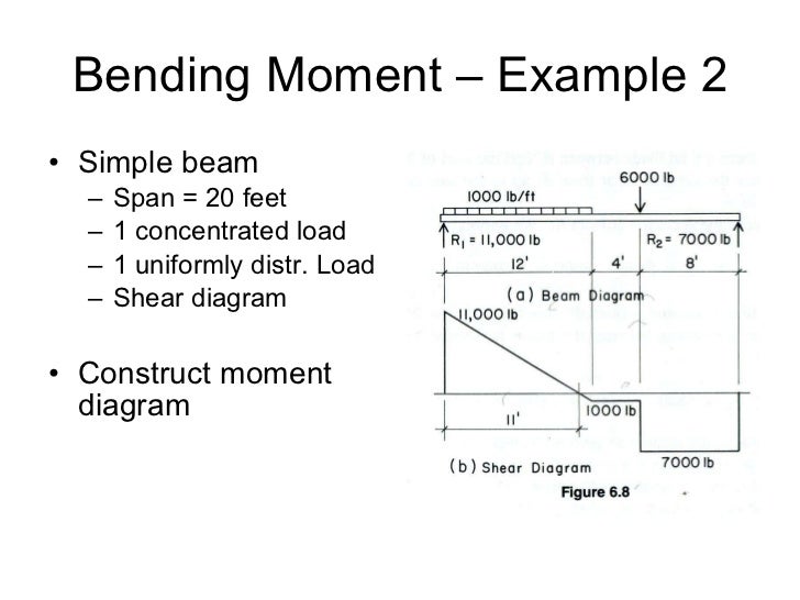
CE 331, Fall 2007 Shear & Moment Diagrams Examples 2 / 7 2. Draw the shear and moment diagram due to dead load. Note the magnitude and location of the maximum bending moment, MD. 3. Calculate the moment due to live load, ML. We will assume that the maximum moment due to dead plus live loads (MD+L) occurs at the location of the maximum moment ...
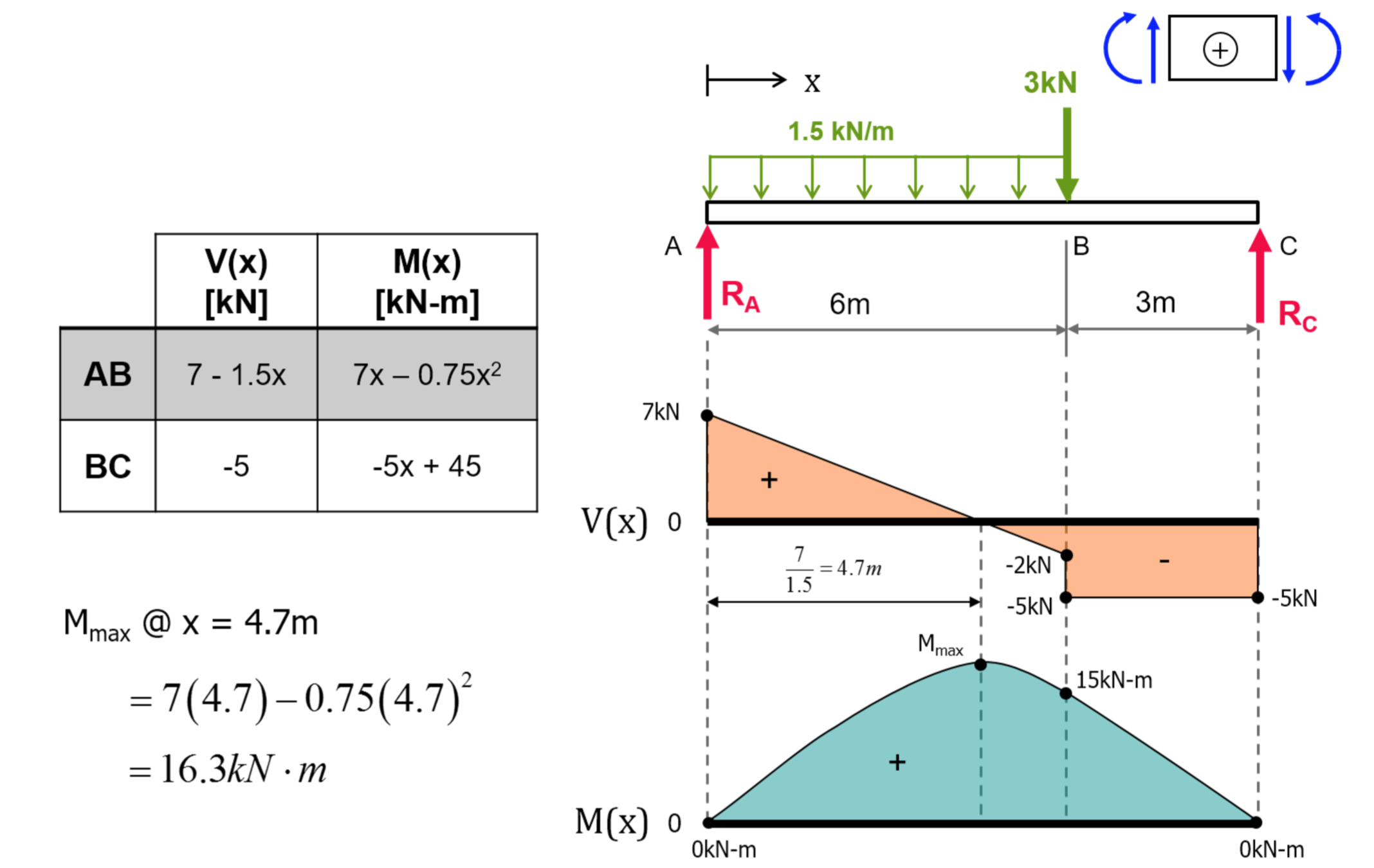
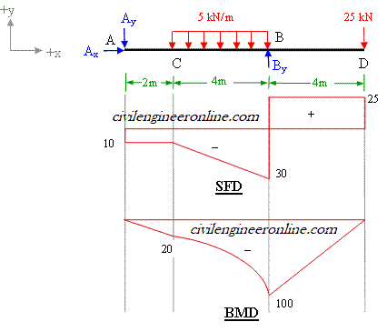
3.2 - Shear Force & Bending Moment Diagrams What if we sectioned the beam and exposed internal forces and moments. This exposes the internal Normal Force Shear Force Bending Moment ! What if we performed many section at ifferent values Of x, we will be able to plot the internal forces and bending moments, N(x), V(x), M(x) as a function Of position!
Bending moment diagram examples.
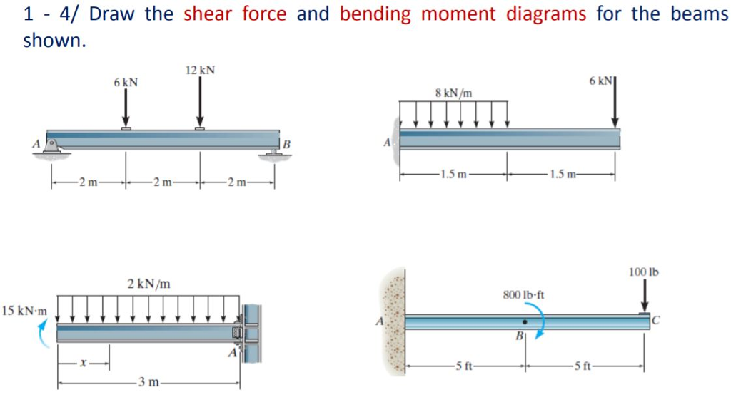
Shear and bending moment diagrams are analytical tools used in conjunction with structural analysis to help perform structural design by determining the value of shear force and bending moment at a given point of a structural element such as a beam.These diagrams can be used to easily determine the type, size, and material of a member in a structure so that a given set of …
Strength of Materials Prof. M. S. Sivakumar ∑ Indian Institute of Technology Madras Problem 3: Computation of Reactions Determine the reactions at A and B …
Statics of Bending: Shear and Bending Moment Diagrams David Roylance Department of Materials Science and Engineering Massachusetts Institute of Technology
Shear force and bending moment diagram examples: Calculate the shear force and bending moment for the beam subjected to a concentrated load, then draw the shear force diagram (SFD) and bending moment diagram (BMD). Answer: By taking the moment at A, MA = 0 – RBy × 5 + 15 × 3 = 0 . RBy = 9 kN . Fy = 0 . RAy + RBy = 15 .
A bending moment (BM) is defined as the algebraic sum of the moments of all the forces either to the left or to the right of a section. Fig. 5.5. Bending moment at section Bending Moment at section x-x = Sign convention of SF and BM For Shear force: We shall remember one easy sign convention, i.e., to the right side of a section, external force
PDF_C8_b (Shear Forces and Bending Moments in Beams) Q6: A simply supported beam with a triangularly distributed downward load is shown in Fig. Calculate reaction; draw shear force diagram; find location of V=0; calculate maximum moment, and draw the moment diagram. 6k/ft 9 ft RA = (27k)(9-6)/9= 9k A B F = (0.5x6x9) = 27k x = (2/3)(9) = 6 ft
Bending Moment at XX is obtained by treating the load to the left of XX as a concentrated load of the same value (w.x) acting through the centre of gravity at x/2. S.F and B.M diagram Therefore, the bending moment at any cross-section XX is . 2.. x 22 x wx Mwx Therefore the variation of bending moment is according to parabolic law.








0 Response to "42 bending moment diagram examples"
Post a Comment