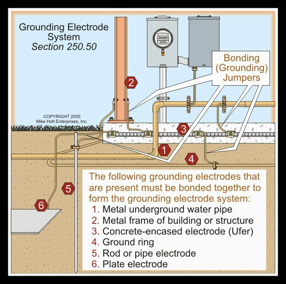
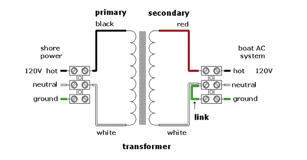
37 transformer grounding and bonding diagram
V outputs are X1 and X4, neutral is the X2/X3 connection For Volt 2-wire: Connect X2 and X4 together and bond to equipment ground and building ground. May 22, · / transformer grounding I've built a service pole with a amp single phase service with a Square D enclosure and breaker. “Transformer Installations & Separately Derived System Grounding”. (This Study Guide other than those established by grounding and bonding connections.”. Installing transformers in accordance with the NEC is critical to ensuring a safe Size the equipment grounding (bonding) conductor for the transformer primary.
Transformer Grounding. Improper neutral-to-case connections in transformers, can cause fire hazards, electrocution, improper operation of protection devices, and power quality problems. Therefore, it’s important to make them only at service equipment and in the transformer only when supplying a secondary panel.

Transformer grounding and bonding diagram
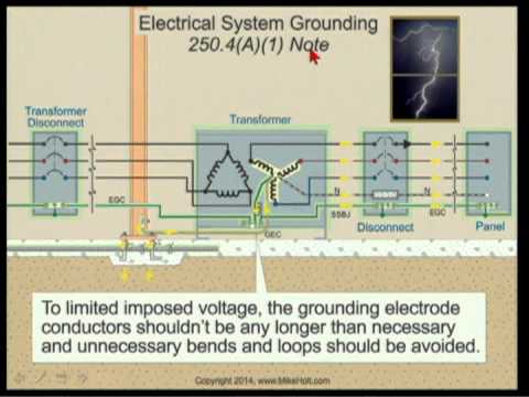
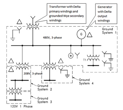
2014 Code Language: 450.10 Grounding (A) Dry-Type Transformer Enclosures. Where separate equipment grounding conductors and supply-side bonding jumpers are installed, a terminal bar for all grounding and bonding conductor connections shall be secured inside the transformer enclosure. Five key components. Following is an overview of essential areas related to bonding and grounding single, solidly grounded, 480V – 208Y/120V, delta-to-wye, 3-phase transformers. System bonding jumper — The 2011 NEC defines the system bonding jumper as “the connection between the grounded circuit conductor and the supply-side bonding ... The CE Code requirements for bonding and grounding are perhaps, The secondary side of this utility transformer represents a start of a Let's look at the Code terminology through a few diagrams of service connections. single phase amp electrical supply from a cooperative transformer is “ Grounding” and “bonding” are important elements of a building's electrical wiring.
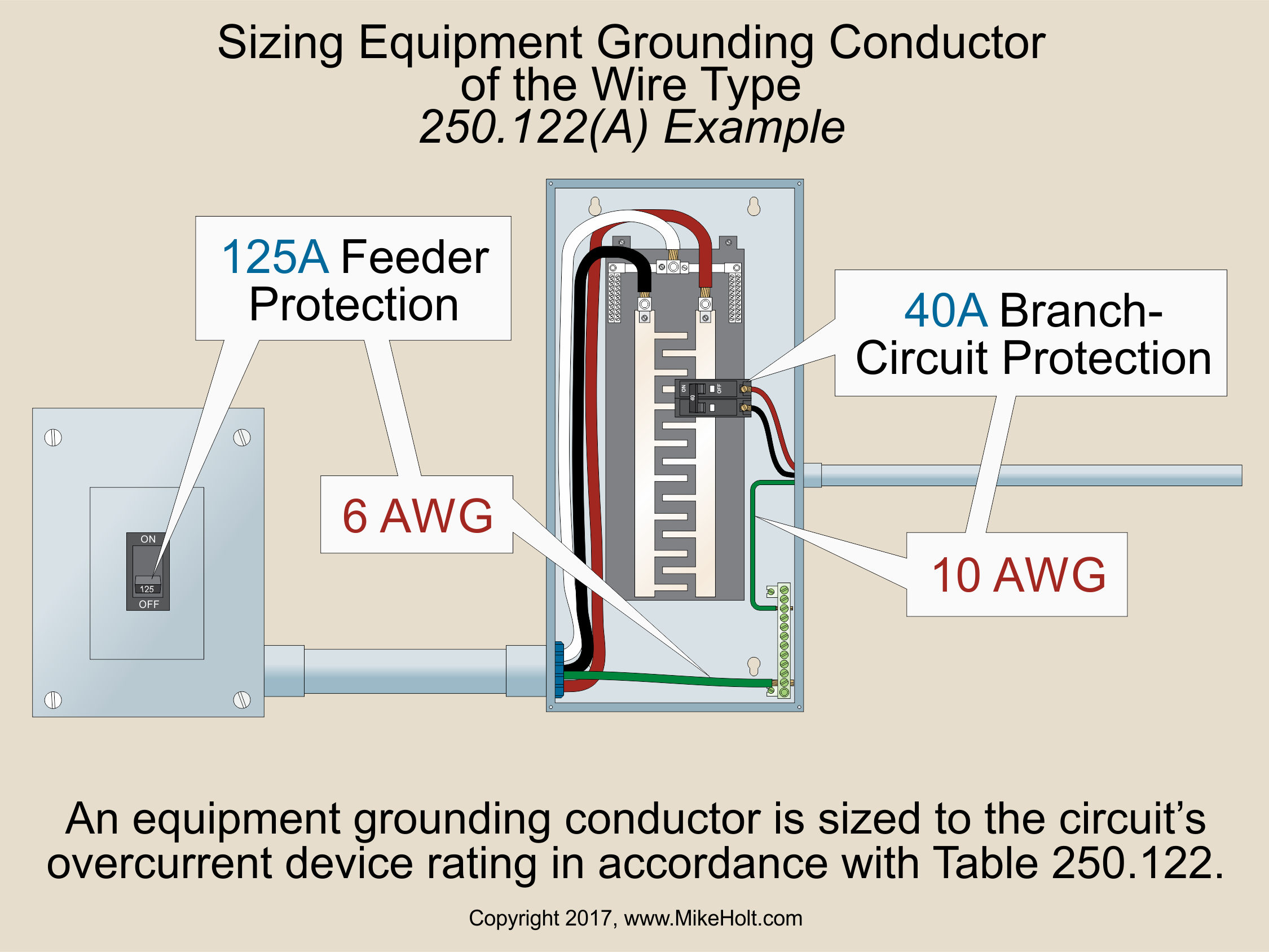
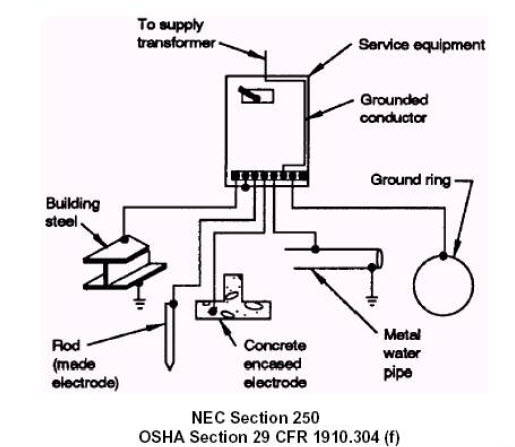
Transformer grounding and bonding diagram. Grounding & Bonding 5 GROUNDING AND BONDING “Grounding” and “bonding” are important elements of a building’s electrical wiring system. They each have different functions, but they work together to make the building’s electrical wiring safe. The Code defi nes “grounding” as the connecting to ground or to a conductive body that Grounding & Bonding; Temporary Power Generation and Electrical Distribution “Grounding, bonding and the creation of an effective ground fault current path is the backbone of electrical safety and shock prevention in temporary power generation and electrical distribution system installations” Based on the 2017 National Electrical Code GROUNDING AND BONDING Using the Tables in Article 250 of the NEC® Continued Bonding Jumper, System — The connection between the grounded circuit conductor and the supply-side bonding jumper, or the equipment grounding conductor, or both, at a separately derived system. Sizing Grounding Electrode Conductors Using Table 250.66 For a 112.5kVA transformer, 135A × 1.25 = 169A, so use a 2/0 AWG conductor rated 175A at 75°C, per Table 310.16. Size the equipment grounding (bonding) conductor for the transformer primary based on the size of primary protection device, per 250.122(A):
The CE Code requirements for bonding and grounding are perhaps, The secondary side of this utility transformer represents a start of a Let's look at the Code terminology through a few diagrams of service connections. single phase amp electrical supply from a cooperative transformer is “ Grounding” and “bonding” are important elements of a building's electrical wiring. Five key components. Following is an overview of essential areas related to bonding and grounding single, solidly grounded, 480V – 208Y/120V, delta-to-wye, 3-phase transformers. System bonding jumper — The 2011 NEC defines the system bonding jumper as “the connection between the grounded circuit conductor and the supply-side bonding ... 2014 Code Language: 450.10 Grounding (A) Dry-Type Transformer Enclosures. Where separate equipment grounding conductors and supply-side bonding jumpers are installed, a terminal bar for all grounding and bonding conductor connections shall be secured inside the transformer enclosure.
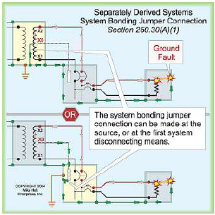
250.30 Separately Derived Systems.
Nec Grounding Conductor Table | Elcho Table

Isolated Ground Transformer Wiring Diagram - Wiring Diagram

Transformer Grounding And Bonding Diagram

30 High Resistance Grounding System Diagram - Wiring ...
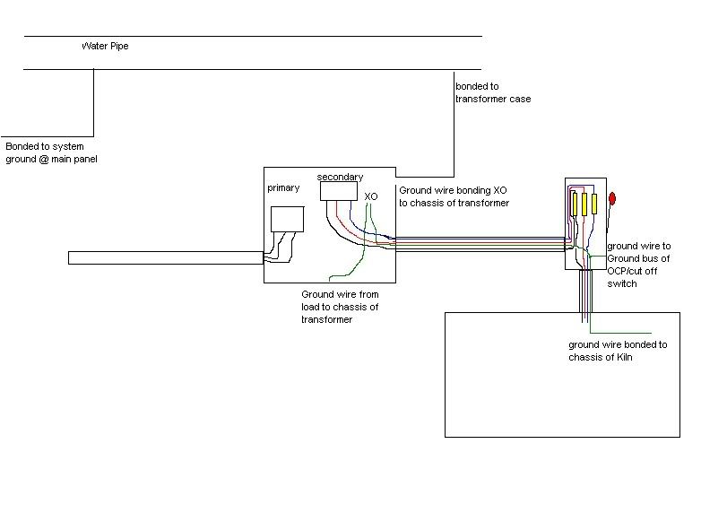
transformer grounding/bonding.
2014 NEC - Systems and Equipment Grounding (13min:49sec ...
Bonding and Grounding, What they mean and which is more

10 general guidelines for installing power transformers | EEP
Transformer Grounding | The Electricity Forum
PDQIE - PDQ Industrial Electric - Grounding and Bonding ...
Consulting - Specifying Engineer | Grounding and bonding ...
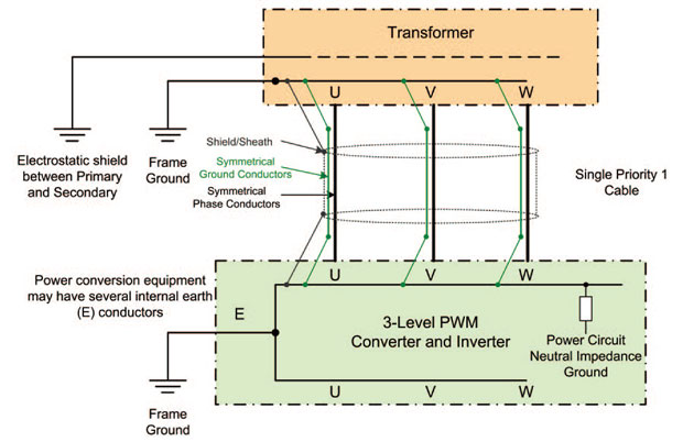
VFD Cable Selection
Clarification transformer circuit | Physics Forums

Main Earth Bonding Regulations - The Earth Images Revimage.Org

Grounding and Bonding, Part 1 | EC&M
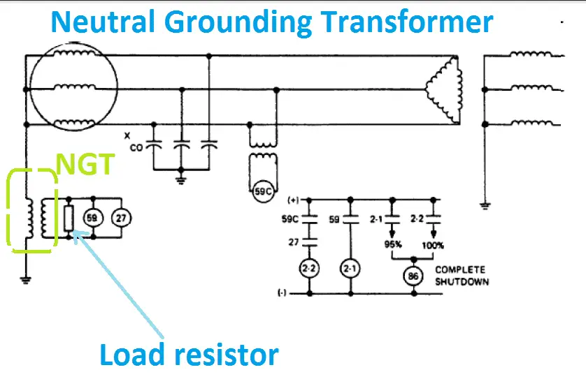
Advantage of Neutral Grounding Transformer NGT | Electrical4u

Closeup of skeleton foot model

PV grounding configuration — northernarizona-windandsun
Isolation vs bonding

250.30(A)(1) System Bonding Jumper.

Square D 480 Volt Transformer Wiring Diagram - Complete ...
.jpg)
InterNACHI Inspection Graphics Library: Electrical ...

How Does Grounding Work? - Electrical - Page 2 - DIY ...
Grounding and Bonding of Electrical Systems Help | EZ-pdh.com
Eames Chair Diagram Schematics - 1951 Chair Poster Hanging on Wall

250.35(A) Separately Derived System.

18 key terms defined in NEC system grounding requirements ...
Stock market chart value. Made with analog vintage lens, Leica APO Macro Elmarit-R 2.8 100mm (Year: 1993)

750V or less transformer bonding and grounding - Code File ...
place to be

Transformer Bonding - ECN Electrical Forums

Blog: A Shocking O.R. Mistruth – "Yes, Doctor, the Patient ...

InterNACHI Inspection Graphics Library: Electrical ...

High Resistance Grounding System Diagram - General Wiring ...

October 2014 ~ Electrical Engineering Pics

Separately Derived System Grounding - stinkypoooo
0 Response to "37 transformer grounding and bonding diagram"
Post a Comment