38 based on the ray diagram and distances shown in figure 1
Thus, for the concave mirror, the reflection of principal ray 1 goes through focal point F, as shown in part (b) of the figure. For the convex mirror, the backward extension of the reflection of principal ray 1 goes through the focal point (i.e., a virtual focus). Principal ray 2 travels first on the line going through the focal point and then is reflected back along a line parallel to the ... We use the diagram shown below to answer the questions. a) angle of incidence: i = 90 - 56 = 34 °. b) angle of reflection r = i = 34 ° (by the law of reflection) c) q = 90 - r = 90 - 34 = 56 °. d) i + r = 34 + 34 = 68 °. Example 2: A ray of light is reflected by two parallel mirrors (1) and (2) at points A and B.
Following figure illustrates the ray diagram for the formation of images by a concave mirror. The position of the object is beyond the centre of curvature of the concave mirror. On the basis of the given diagram, answer the questions.

Based on the ray diagram and distances shown in figure 1
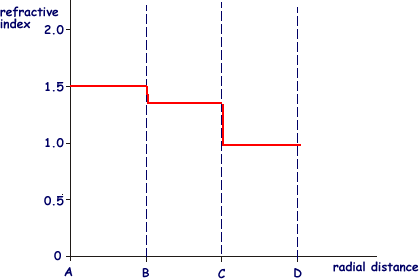
Which of the following ray diagrams is correct for the ray of light incident on a concave mirror as shown in figure? Answer: Explanation: Ray of light parallel to the principal axis towards the mirror after reflection from the mirror will pass through the focus. Question 24. The refractive index of four substances P, Q, R and S are 1.50, 1.36, 1.77 and 1.31 respectively. The speed of light … The four steps of the process for drawing a ray diagram are listed, described and illustrated below. 1. Draw the image of the object. Use the principle that the object distance is equal to the image distance to determine the exact location of the object. Pick one extreme on the object and carefully measure the distance from this extreme point ... Figure 1. (a) A ray of light crosses a boundary where the speed of light increases and the index of refraction decreases. That is, n 2 < n 1. The ray bends away from the perpendicular. (b) The critical angle θc is the one for which the angle of refraction is. (c) Total internal reflection occurs when the incident angle is greater than the ...
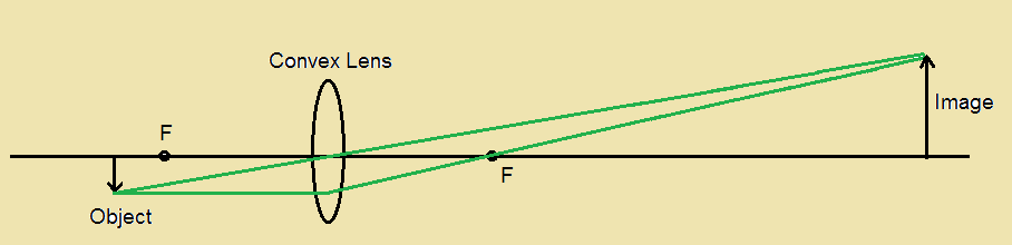
Based on the ray diagram and distances shown in figure 1. Following figure illustrates the ray diagram for the formation of images by a concave mirror. The position of the object is beyond the centre of curvature of the concave mirror. On the basis of given diagram, answer the questions. If the focal length of the concave mirror is 10 cm, the image formed will be at a distance _____. Figure 1 ShOWS parallel rays of light being refracted by a convex lens. Figure 1 What is distance 'X' called? / [1 mark] or Lenses can be used to form the image of an object. Complete the ray diagram in Figure 2 to show how a convex lens forms the image of the object. Use an arrow to represent the image. Do not write outside the box 2 [2 marks] The ray tracing technique shows qualitatively where the image will be located. The distance from the mirror to the image, d i, can be found from the mirror equation: do di f 1 1 1 + = do = distance from object to mirror di = distance from image to mirror f = focal length Sign Conventions: di is positive if the image is in front of the mirror ... To answer such questions, we can use a ray diagram to determine where an image is formed and what its characteristics are. EXPLORATION 23.2 – Using a ray diagram to find the location of an image Figure 23.9: An arrow located some distance in front of a plane mirror. Step 1 – An arrow is placed in front of a vertical plane mirror, as shown
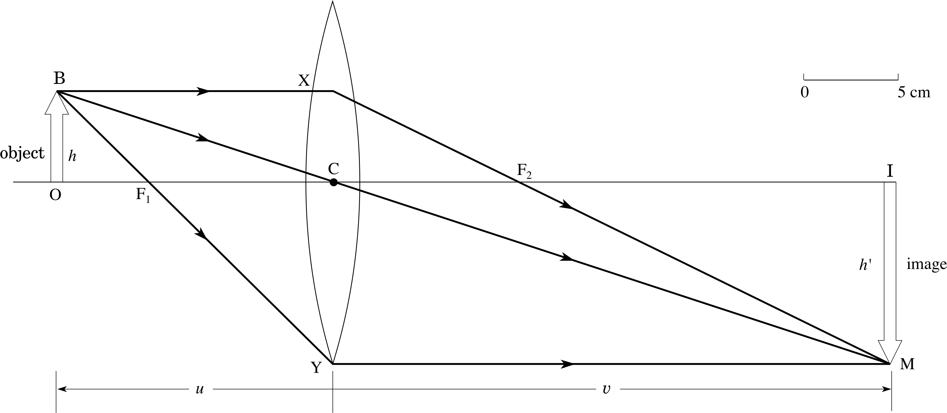
The figure shows three rays from many rays that emanate from the tip of the arrow. These three rays can be traced by using the ray-tracing rules given above. Ray 1 enters the lens parallel to the optical axis and passes through the focal point on the opposite side (rule 1). Ray 2 passes through the center of the lens and is not deviated (rule 2). Some ray diagrams may also show a third ray. Convex lenses. The type of image formed by a convex. lens depends on the lens used and the distance from the object to the lens. Figure 1 shows the principal-ray diagram of the image formation by a converging lens with focal length f and object distance s = 2f/3 to the left of the lens. a. Use the equation m = y'/y = -s'/s to find the image distance s' in terms of f. b. Based on your result, is the image real or virtual? Is it to the left or right of the 39 . Show that, for a flat mirror, h i = h o. h i = h o, given that the image is the same distance behind the mirror as the distance of the object from the mirror. 40 . Use the law of reflection to prove that the focal length of a mirror is half its radius of curvature. That is, prove that. f = R / 2. f = R / 2.
The energy meter, based on the photoelectric effect, uses a detector with a work function of ... Based on the ray diagram and distances shown in Figure 1, ... Look at the ray diagram shown in the figure. The distances are measured from the pole P. The incident ray (from the object to the mirror) is from the left to the right. Thus, u, v and f are all negative (by sign convention). The u versus v graph is shown in the figure. The important points in this figure are: Distance between man and the image of chart = Distance between man and the mirror + Distance between mirror and the image of the chart = 2 m + 2.5 m = 4.5 m Question 39 A ray of light strikes a plane mirror PQ at an angle of incidence of 30 o , is reflected from the plane mirror and then strikes a second plane mirror QR placed at right angle to ... Using the HR Diagram in Figure 1, estimate the luminosity and temperature of all the stars listed in Table 1 and record their values in Table 1. Now calculate the stars’ radii in units of meters and solar radii (see EQs #2 and 3). You must show your calculation explicitly for at least one star in the space below. Enter the radii in units of meters and solar radii in Table 1.
draw a labelled ray diagram to locate the image of an ...
30 Mar 2019 — Based on the ray diagram and distances shown in Figure 1, the focal length of the lens is: 3 cm. 4 cm. 8 cm. 16 cm. 1. 7 comments
Flagpoles 🤙ðŸ»
(See Figure 5, and see ray 2 in Figure 1 and Figure 2.) A ray entering a converging lens through its focal point exits parallel to its axis. (The reverse of rays 1 and 3 in Figure 1.) A ray that enters a diverging lens by heading toward the focal point on the opposite side exits parallel to the axis. (The reverse of rays 1 and 3 in Figure 2.)
A Cyberphysics Page
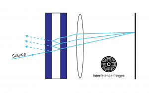
monochromatic light€was directed at two closely spaced slits, as shown in Figure 1. A pattern of bright and dark fringes due to this light passing through the slits was seen on the screen. Figure 1 (a)€€€€ Explain why this fringe pattern was formed. You may be awarded marks for the quality of written communication in your answer.

(a) Histogram of inter-trabeculae distances (mm) in the 25 ...
Feb 10, 2016 · 8. Pre-Medical. Mar 15, 2016. #1. Mar 15, 2016. #1. Content from Imgur. The question asks for the focal length of the lens. All parallel lines going through converging lens should pass through focal point, and light from a single source going through converging lens should exit in parallel rays...but the figure shows neither.

Cue Mechanics Pool School - Some league players and ...
the initial distance between you and your image be d 1. After you run for 1 s at 2 m/s, the distance between you and your image is d 2. You have moved 2 m, and your image has moved 2 m, so the distance between you and your image has decreased by 4 m – at a speed of 4 m/s. Your image approaches you at a speed of (d 1 - d 2)/(1s) = 4 m/s d 1 2 m d 2 2 m

Image formation in a concave mirror. The object O sends ...
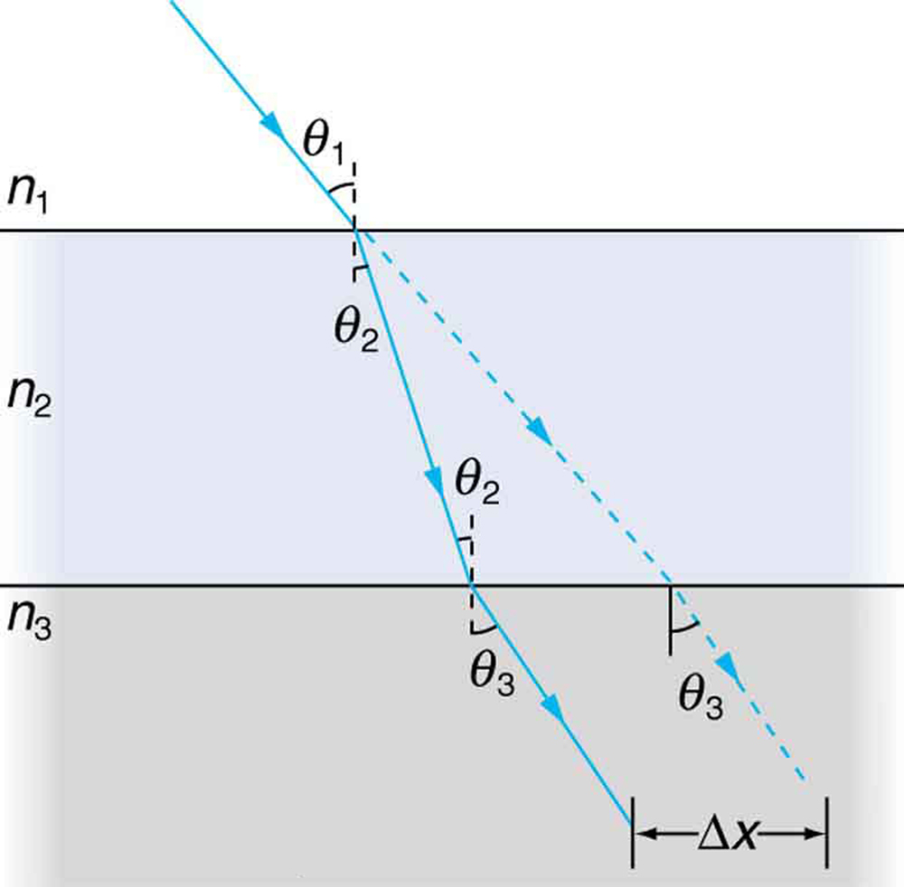
The ray of light shown in Figure passes from medium 1. to medium 2 to medium 3. The index of refraction in medium 1 is nY, in medium 2 it is n2> n1, and in medium 3 it is n3 > n2 Show that medium 2 can be ignored when calculating the angle of refraction in medium 3; that is, show that n1 sin θ1 = n3 sin 03. Solution:
Solved: Based On This Figure, Is It Possible For An Electr ...
(c) In the experiment shown in the diagram below, the fringe pattern in the image in part (a) is produced. s = 0.60 ± 0.02 mm . D = 1.500 ± 0.002 m . Using these data and your answers to part (a) and part (b), determine
Solved: Part A Consider The Following Diagrams Noting That ...
03.08.2020 · Draw a ray diagram to show the path of the reflected ray corresponding to an incident ray of light parallel to the principal axis of a concave mirror. Mark the angle of incidence and angle of reflection on it. (CBSE 2014, 2017) Answer: Incident ray AM is parallel to the principal axis of a concave mirror. Hence, it will pass through the principal focus (F) of the …

Top scoring HypoGen pharmacophore HypoA1 along with intra ...
Concave Mirror Ray Diagram. Concave Mirror Ray Diagram lets us understand that, when an object is placed at infinity, a real image is formed at the focus. The size of the image is much smaller compared to that of the object. When an object is placed behind the center of curvature, a real image is formed between the center of curvature and focus.
An object is placed 3 centimeters to the left of a convex ...
1/v1 1/v2 1/v3 Figure 4: Travel-time diagram for the 3-layer case In the model shown in Figure 4 the velocites are v1=3.5km/s, v2=5km/s, v3=8km/s. The layer thicknesses are h1=10km and h2=25km. 3. Reduced time In refraction seismology as well as in global seismology we often find travel-time diagrams where reduced time is used. In principle this means that the refraction …

Physics 4C HYNyein: Experiment 9: Concave and Convex Mirrors
3.1.1 Basic Operation of Oscilloscope Figure 1: Block diagram of a basic cathode-ray oscilloscope The basic parts of CRO are shown in Figure 1. In inexpensive, general-purpose oscilloscopes, the left horizontal deflection plate (looking toward the screen) and the lower vertical deflection plate are sometimes connected to ground.

Rietveld refinement diagram based on synchrotron X-ray ...
Figure Based Short Answers. Question 1: ... The ray diagram is shown in figure. For the object AB, the images is A'B'. ... This is shown in figure. The distance of second focal point F 2 from the optical centre O of the lens (i.e., OF 2) is called the second focal length f 2.

ins:billow926
The ray diagram shows the position and size of the image, I, of an object, O, formed by a lens, L. (a) What type of lens is shown in the ray diagram? _____ (1) (b) Name the point labelled P. _____ (1) (c) The ray diagram has been drawn to scale. Use the equation to calculate the magnification.
TN2020-06 Etalons Explained - Manx Precision Optics
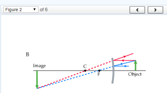
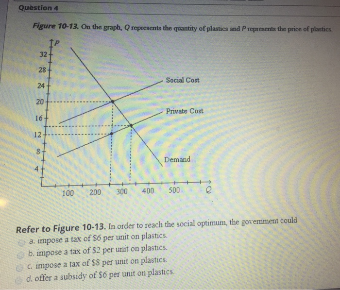
Figure 1. Figure 2. Part A. Consider the following diagrams noting that the scale is different between diagrams. In these diagrams, C and F represent the center of curvature and the focal point of the convex mirror, respectively. The image formed by the mirror is obtained using the ray tracing technique. Which diagram (s) are correct? (Figure 1)
A schematic diagram of the microfocus X-ray CT-based ...
(Figure 1) shows a small plant near a thin lens. The ray shown is one of the principal rays for the lens. Each square is 1.5 cmcm along the horizontal direction, but the vertical direction is not to the same scale. Use information from the diagram to answer the following questions: Using only the ray shown, decide what type of lens this is.

The two mirrors in the figure below meet at a right angle ...
(But note that this set of diagrams differs from the prior sets.) Rank the diagrams based on the speed at which the other galaxy is moving away from your galaxy as the universe expands, from fastest to slowest. If two (or more) of the diagrams show galaxies moving at the same speed, show this equality by dragging one diagram on top of the other(s).
(a) XRD profiles of representative samples with increasing ...
(a)€€€€ Complete Figure 1 by drawing wave fronts after they have left the glass block. (1) (b)€€€€ Figure 2 shows a ray of light incident on a semi-circular glass block. Figure 2 Complete the ray diagram in Figure 2 . •€€€€€€€ Draw the ray of light passing through and leaving the glass block.

Summary of Amino Acid Interaction Energies Based on the ...
Images 1 and 2 result from rays that reflect from only a single mirror, but image 1,2 is formed by rays that reflect from both mirrors. This is shown in the ray-tracing diagram in part (b) of . To find image 1,2, you have to look behind the corner of the two mirrors.
Comparison of the effective solid angle calculated for the ...
Figure 6: Problem 32-21 (c) Compute the image size, using Eq. 32-3. Solution: m = di do hi = mho = di do ho = 6.0cm 18cm 3.0mm = 1.0mm. Problem Giancoli 32-21 (II) Show, using a ray diagram, that the magni cation m of a convex mirror is m = di/do, just as for a concave mirror.[Hint: Consider a ray from the top of the object that re
Solved: Question 13 Figure 6-33 The Diagram Shows The Effe ...
Lloyd Dingle, Mike Tooley · 2006 · Technology & EngineeringRay diagrams To determine the position and size of the image any two ofthe following three rays(Figure 4.120) need to be drawn: 1. A ray of light parallel ...
(a) The phylogenetic tree of miRNAs shown in Table 1 based ...
Question 1 - Case Based Questions (MCQ) - Chapter 10 Class 10 - Light - Reflection and Refraction (Term 1) Following figure illustrates the ray diagram for the formation of images by a concave mirror. The position of the object is beyond the centre of curvature of the concave mirror. On the basis of the given diagram, answer any four questions ...

The Hubble diagram or the velocity-distance relation plot ...
In general, if sin q1 > (n2 / n1), we have NO refracted ray; we have TOTAL INTERNAL REFLECTION. For example, light in water which is incident on an air surface with angle q1 > qc = sin-1(1.0/1.33) = 48.8 °will be totally reflected. This property is the basis for the optical fiber communication. incident ray reflected ray refracted ray q2 q1 qr ...

X-ray diffraction (XRD) patterns of samples based on TiO2 ...
Richard Boyle, Bahram Parvin, Darko Koracin · 2010 · Computers(b) Ray diagram illustrating the formation of the two images, ... As shown in Figure 2(g), the prism is placed at the end of the camera lens.

Physics 4C HYNyein: Experiment 9: Concave and Convex Mirrors
(c) €€€€R and S are two charged parallel plates, 0.60 m apart, as shown in Figure 2 . They are at potentials of + 3.0 V and + 1.0 V respectively. Figure 2 € (i)€€€€€ On Figure 2 , sketch the electric field between R and S, showing its direction. (2) (ii)€€€€€Point T is mid-way between R and S.

HG-unique criteria. Shown are WC and HG A•T and G•C bps ...
Figure 1. (a) A ray of light crosses a boundary where the speed of light increases and the index of refraction decreases. That is, n 2 < n 1. The ray bends away from the perpendicular. (b) The critical angle θc is the one for which the angle of refraction is. (c) Total internal reflection occurs when the incident angle is greater than the ...

An example of partial shape matching of anterior-inferior ...
The four steps of the process for drawing a ray diagram are listed, described and illustrated below. 1. Draw the image of the object. Use the principle that the object distance is equal to the image distance to determine the exact location of the object. Pick one extreme on the object and carefully measure the distance from this extreme point ...

Pulse-height spectrum of the 241 Am source (1-59.6 keV ...
Which of the following ray diagrams is correct for the ray of light incident on a concave mirror as shown in figure? Answer: Explanation: Ray of light parallel to the principal axis towards the mirror after reflection from the mirror will pass through the focus. Question 24. The refractive index of four substances P, Q, R and S are 1.50, 1.36, 1.77 and 1.31 respectively. The speed of light …

Physics 4C HYNyein: Experiment 9: Concave and Convex Mirrors

Dependence of r on the ray lateral distance h from the ...

Plane-Based Sampling for Ray Casting Algorithm in ...
PPLATO | FLAP | PHYS 6.3: Optical elements: prisms, lenses ...

Schematic figure of the X-ray diffraction measurement ...

draw the ray diagram to show the image formation and an ...
The Law of Refraction | Physics
which type of lens is used in projector - Physics ...

Performance Evaluation of the Thick Pinhole Gamma Rays ...
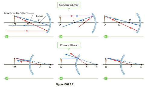
The top row of Figure CQ23.2 shows three ray diagrams for ...

Draw a labelled ray diagram for the formation of image by ...
0 Response to "38 based on the ray diagram and distances shown in figure 1"
Post a Comment