40 24 volt alternator wiring diagram
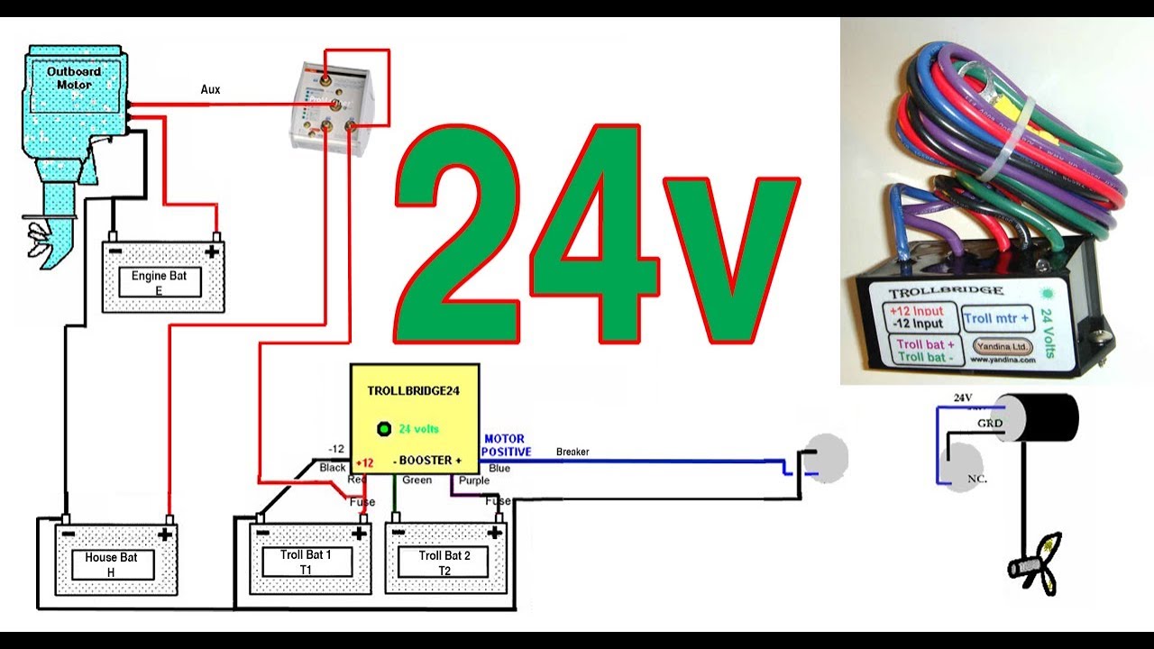
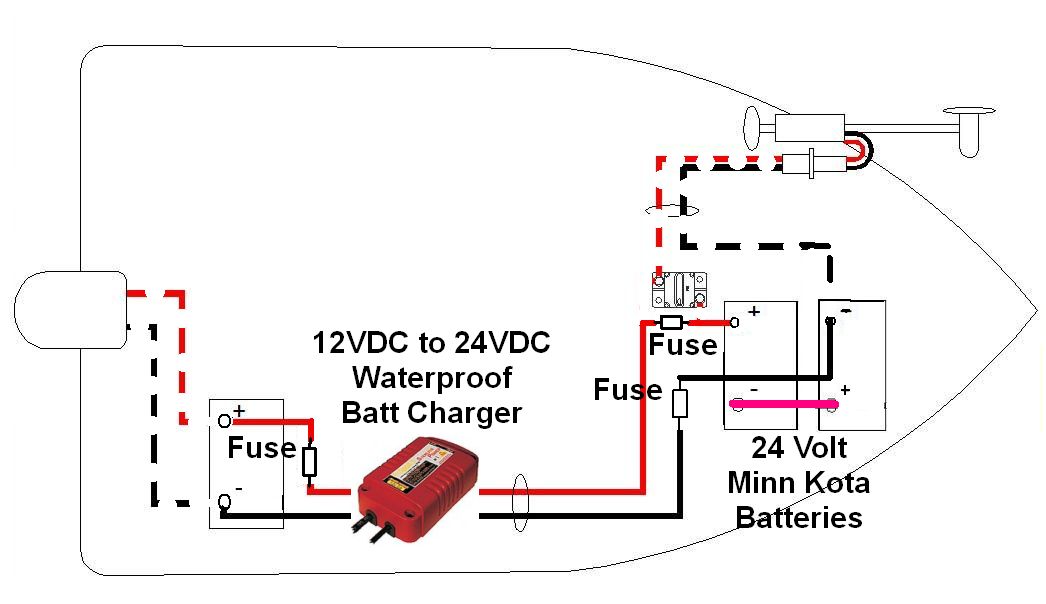
PRESTOLITE 8RG3008 24 VOLT ALTERNATOR WIRING DIAGRAM PDF. Should the voltage raise or decrease drastically, the regulator will increase or decrease the output of the alternator to maintain a steady flow of voltage to the battery. Cooper Wiring 4409-BOX Armored Yellow 3 Wire 20 Amp 5 on Wiring Amp 5. We are promise you will like the 2290317527 ... 13+ 24 Volt Alternator Wiring Diagram. To identify an alternator system, inspect wire or wires that come from under or behind the blower housing. I've seen a lot of videos where people mount charging systems in their boats and plug them in to charge when they get home. Then the charge volts across the battery bank should read 26 to 29.
Dec 17, 2021 · The charging from alternator is typically very slow (less than 10 amps) and should, generally, not be relied on to provide adequate power for recharging deeply depleted house battery banks. ... the adds at the bottom (that I almost signed up for) etc. Oh, I bought your 12-volt wiring diagram that I have no use for. The mistakes I made so far: 1 ...

24 volt alternator wiring diagram
24 Volt Battery Wiring Diagram – 12 24 volt battery wiring diagram, 24 volt battery bank wiring diagram, 24 volt battery charger wiring diagram, Every electric structure is composed of various different parts. Each part should be placed and linked to different parts in specific way. If not, the structure will not work as it should be. Step 4. Follow the red, 24-volt cable from the positive battery terminal. It leads to the alternator and connects to the terminal labeled "B" or "Bat." Place the sensor on the end of the red wire from the multimeter onto the metal alternator terminal. If you have a two-wired alternator, place the metal sensor on the end of the black wire onto ... #chevy alternator wiring diagram. #10si alternator wiring. #24 volt delco 10si three wire alternator diagram. #gm alternator wiring diagram. #delco 10si. 10Si Alternator Operating Principles. A typical 10Si series wiring diagram is illustrated in Figure 3. The basic operating principles are explained as follows. The No. 2 terminal is connected ...
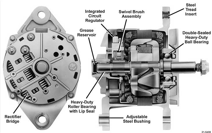
24 volt alternator wiring diagram. Understanding the Alternator • Four wires connect the alternator to the rest of the charging system. • B is the alternator output wire that supplies current to the battery. • IG is the ignition input that turns on the alternator/regulator assembly. • S is used by the regulator to monitor charging voltage at the battery. Solar Panel Wiring Diagram and Installation Tutorials. Electrical Technology. 15 ... a second inverter designed to take the 12 volt + DC voltage directly from the charger/controller and convert it to 120 AC with a power drop detector that will swiitch-back to batteries when the solar alone will not support you load draw. ... They can be ... Jul 01, 2020 · A 12 volt solar panel can not charge a 24 volt battery. A typical 12 volt solar panel has an operating voltage of around 18 volt. This voltage goes into a charge controller that regulates it to charge a 12 volt battery. To charge a 24 volt battery, you need a 24 volt solar panel that outputs above 36 volts. Connect the red lead to a 24 volt post on the bank of chassis batteries (refer to the wiring diagram on the inside of the RH side chassis door). Your multimeter used in this fashion is gong to give you precise readings. The gauge inside the coach may be less precise because there is a current drop when the voltage passes through a long run of wire.
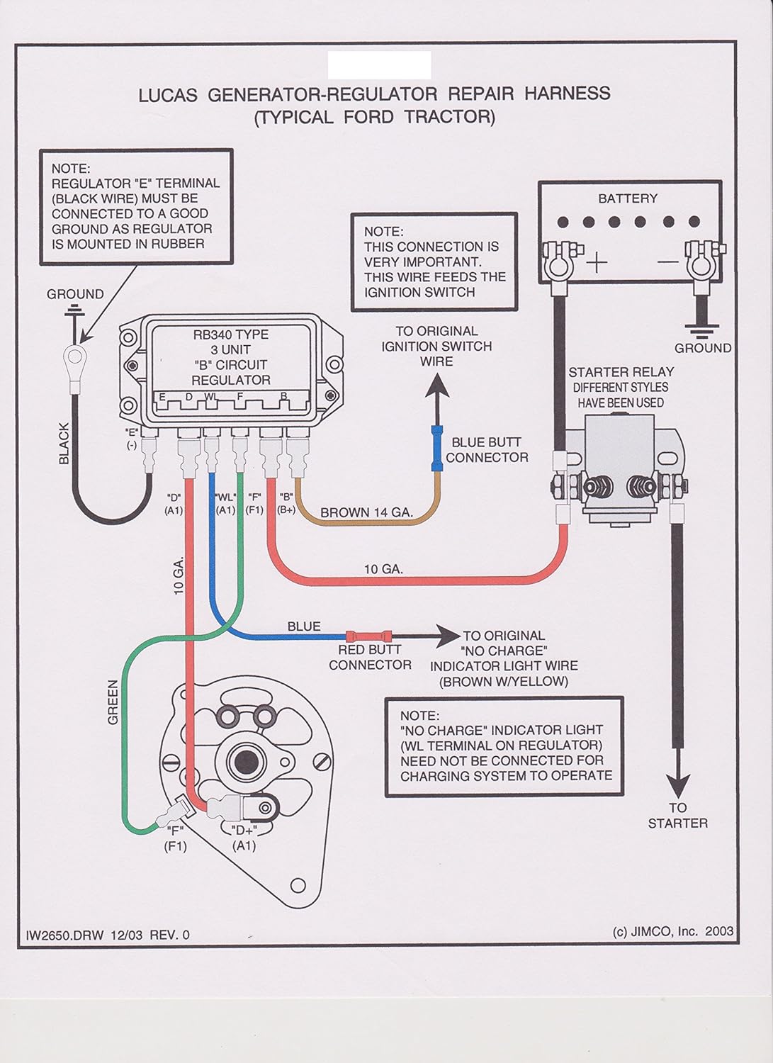
May 22, 2019 · : 2 from the alternator, 1 from/to the battery positive, 1 to ground, (Negative) and another also to the battery positive when the ignition is turned on. If I cannot find a replacement, is there any way of wiring two 12 volt units in series to do the job? Perhaps there is another make of bike with a single phase 6 volt system that would be ... A typical 3-wire alternator wiring diagram with an internal voltage regulator. Computer-Controlled Voltage Regulation. Many late-model vehicles use the engine computer, which is often referred to as the powertrain control module (PCM), to control alternator output. Most modules use an internal driver to turn the alternator’s field circuit on ... turn switch, electric fan, horn, battery feed, alternator and alternator exciter wire, coil, and air conditioning. Included in the 18-circuit kit are trunk accessory, door locks, power windows, reverse switch and electric fuel pump. (24v system) (alternator output [b+] terminal to battery positive terminal at full output). for obtaining additional wiring installation information, see heavy duty application manuals or contact a remy inc. representative. follow engine or vehicle manufacturer’s instructions for removing the old alternator from the
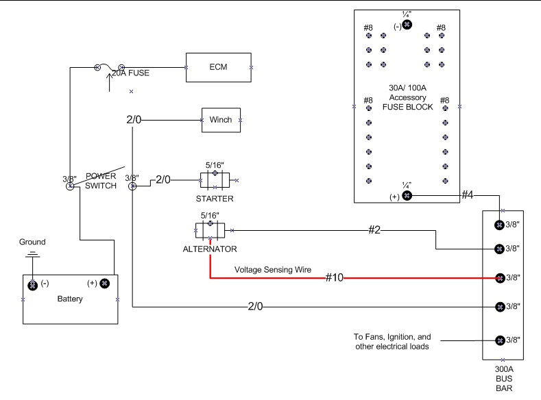
Oct 26, 2018 · 120v Ac Capacitor Motor Reversing Switch Wiring Diagram 26.10.2018 26.10.2018 0 Comments on 120v Ac Capacitor Motor Reversing Switch Wiring Diagram To complete a single phase motor direction change, you will need to motors go in forward and reverse depending on their wiring and the resulting magnetic field. (tach) wire if needed and other necessary wiring. Connect alternator to Balmar regulator wiring harness as indicated in wiring diagram included on Page 12. The alternator’s positive and ground cables should be sized according to the chart on Page 3. 7. If a new regulator is being installed along with the alternator, complete its wiring ... Following your diagram wiring for the battery alternator relationship. Your alternator works with your battery so the alternator wiring to the battery is very important to maintain top alternator amp wire load, this is important with 12v battery setups as well as 24v battery systems. ... 24 Volt 30-50 12 AWG 10 AWG 8 AWG 6 AWG 6 AWG 4 AWG 24 ... 7 3.0 CONTENTS OF THE PAINLESS WIRE HARNESS KIT Refer to Figure 3-1 to take inventory. See that you have everything you're supposed to have in this kit. If anything is missing, contact the dealer where you obtained the kit or Painless Performance at (800) 423-9696.
4020 12 Volt Alternator Wiring Diagram - Wiring Forums
Mar 24, 2019 · duramax engine parts diagram - GMC Sierra question.6 Duramax Firing Order Diagram ~ hello friends our site, this is images about 6 duramax firing order diagram posted by Maria Nieto in 6 category on Nov 10, You can also find other images like wiring diagram, parts diagram, replacement parts, electrical diagram, repair manuals, engine diagram ...

Noministnow: Bosch 24 Volt Alternator Wiring Diagram
#chevy alternator wiring diagram. #10si alternator wiring. #24 volt delco 10si three wire alternator diagram. #gm alternator wiring diagram. #delco 10si. 10Si Alternator Operating Principles. A typical 10Si series wiring diagram is illustrated in Figure 3. The basic operating principles are explained as follows. The No. 2 terminal is connected ...

Mitsubishi Alternator Wiring Diagram 24 Volt - Wiring Diagram
Step 4. Follow the red, 24-volt cable from the positive battery terminal. It leads to the alternator and connects to the terminal labeled "B" or "Bat." Place the sensor on the end of the red wire from the multimeter onto the metal alternator terminal. If you have a two-wired alternator, place the metal sensor on the end of the black wire onto ...

12 Volt Delco Alternator Wiring Diagram - Wiring Diagram ...
24 Volt Battery Wiring Diagram – 12 24 volt battery wiring diagram, 24 volt battery bank wiring diagram, 24 volt battery charger wiring diagram, Every electric structure is composed of various different parts. Each part should be placed and linked to different parts in specific way. If not, the structure will not work as it should be.

gmwiringdiagram: Mitsubishi Alternator Wiring Diagram 24 Volt
26SI / 21SI alternator specifications :: Delco Remy

24 Volt Jasco Alternator Wiring Diagram - Wiring Diagram
Ford 9n Wiring Diagram 12 Volt 1 Wire Alternator - Wiring ...
51 24 Volt Alternator Wiring Diagram - Wiring Diagram Plan
12 Volt Delco Alternator Wiring Diagram - Search Best 4K ...

Delco 24 Volt Starter Wiring Diagram - Wiring Diagram

I have 4010 deer with a 24 system that was original i ...
Farmall 400 12 Volt Wiring Diagram - Wiring Diagram & Schemas
12 Volt Trolling Motor Wiring Diagram – Database | Wiring ...

NEW DELCO TRACTOR 24 VOLT REPLACEMENT ALTERNATOR 1-WIRE ...

24SIâ„¢ Brush Type Alternator | Delco Remy

24 Volt Battery Wiring Diagram — UNTPIKAPPS

Mitsubishi Alternator Wiring Diagram 24 Volt - Wiring Diagram

Porsche 24 Volt Alternator Wiring - Wiring Diagram

Porsche 24 Volt Alternator Wiring - Wiring Diagram
24 Volt Alternator Wiring Diagram - Wiring Diagram

24 Volt Jasco Alternator Wiring Diagram Pdf - Wiring ...
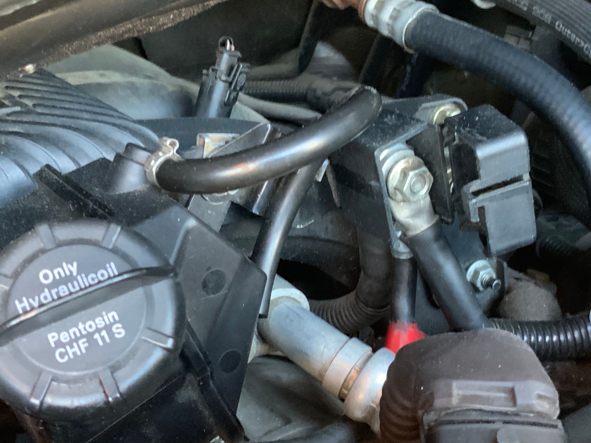
Porsche 24 Volt Alternator Wiring - Wiring Diagram

Mount Fuji at Sunset
Mitsubishi Alternator Wiring Diagram 24 Volt - Wiring Diagram

How To Wire A Light Switch To, Volt Battery Nice Wiring ...

Alternator Wiring Diagram Delco Remy - WIRGREM
![Avenida Vinte e Quatro de Julho [Freguesia de Estrela]](https://images.unsplash.com/photo-1626262316322-9354ef83bee9?ixlib=rb-1.2.1)
Avenida Vinte e Quatro de Julho [Freguesia de Estrela]

Ford 9n Wiring Diagram 12 Volt 1 Wire Alternator - Wiring ...

Mixed 12-volt and 24-volt Primary Power with Three ...

24 Volt Battery Wiring Diagram — UNTPIKAPPS
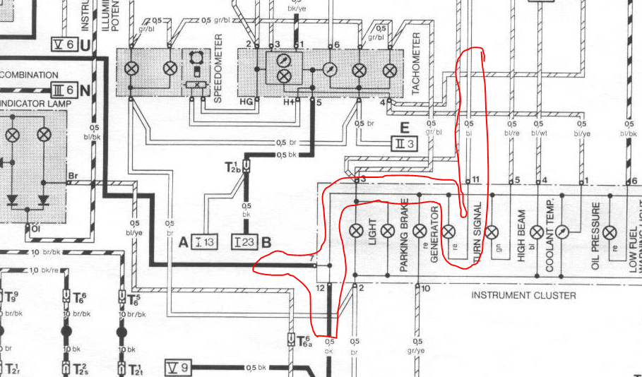
Porsche 24 Volt Alternator Wiring - Wiring Diagram

I have a 4020 Deere and my grandfather converted the ...

Birthday
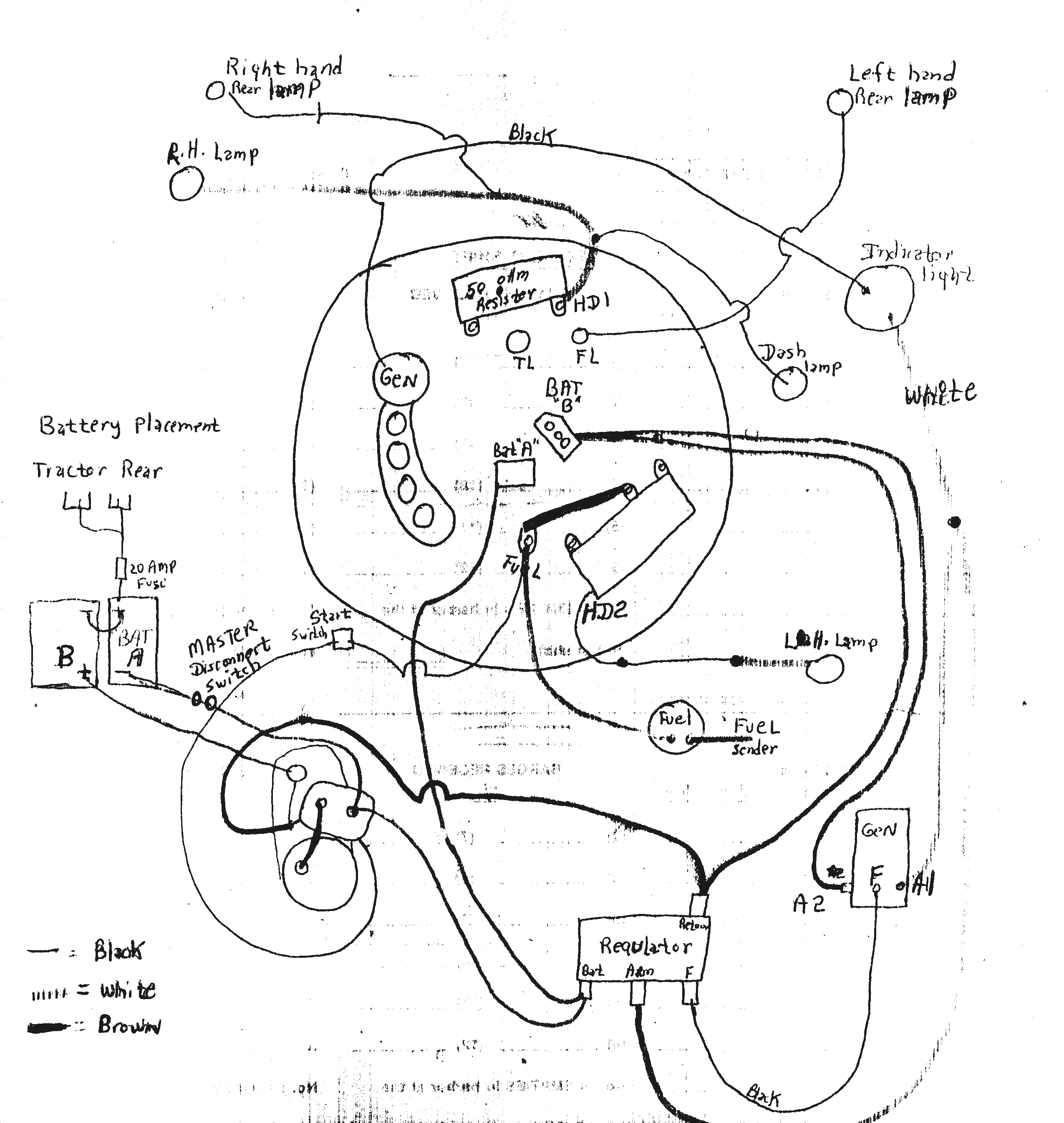
The John Deere 24 Volt Electrical System Explained

41DD 24 Volt 8030 Alternator Wiring Diagram | Ebook Databases
Porsche 24 Volt Alternator Wiring - Wiring Diagram

24V Alternator Wiring Diagram - Wiring Diagram And ...
Spark, Redux

Reyhan Blog: Bosch 24 Volt Alternator Wiring Diagram
0 Response to "40 24 volt alternator wiring diagram"
Post a Comment