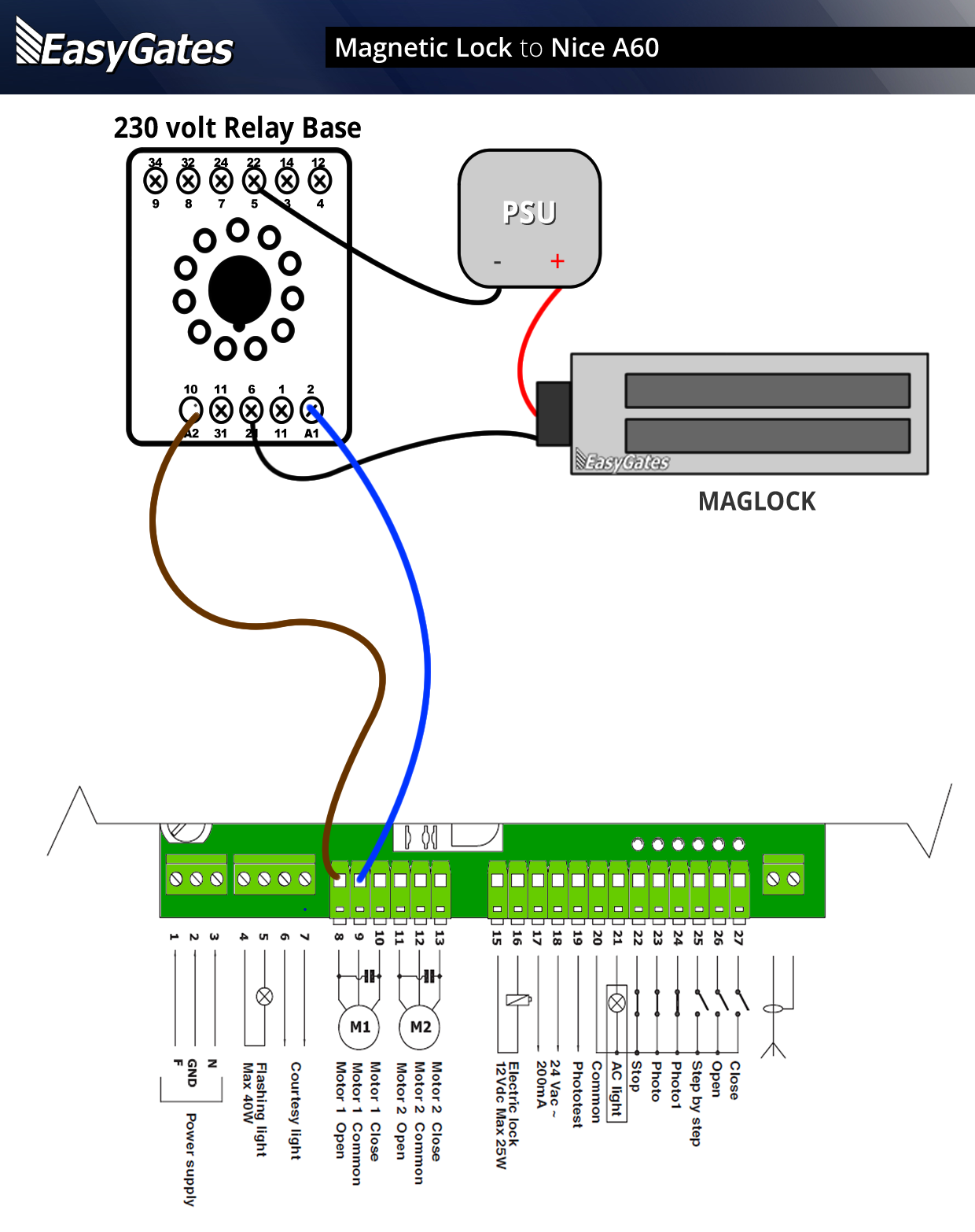
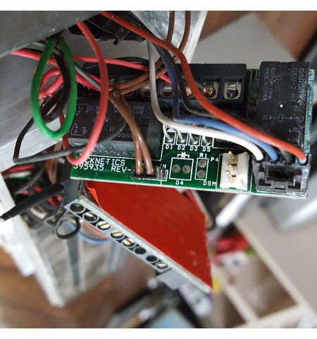
42 locknetics maglock wiring diagram
Created Date: 10/30/2018 11:41:16 AM Locknetics provides the most complete selection of electromagnetic locks in the industry. The GF3000 Series Shear Lock features a patented design offering advances over any Shear Lock on the market. Unique mounting features provide a "floating" action of both the lock assembly and the armature. This design
Monitored Maglock Wiring Diagram. Door entry maglock install guide smart security mag ock access control how to wire with a lock magnalock models m32 m62 and m82b installation instructions cables wiring diagram kisi electromagnetic locks manualzz keypad strike architecture basic magnetic system hubpages rgl exml1200 gate monitored external ...

Locknetics maglock wiring diagram
Wiring for the electromagnet must enter the top of the unit through the wire access hole drilled in the frame header (see template). Be certain provisions can be made to bring the wire through the header into the top of the unit. Frame conditions may require the use of filler plates and/or angle brackets. These items are available from Locknetics. For double doors without a center mullion, the Securitron DM62 Magnalock supplies two model M62 Magnalocks in a single, brushed stainless steel housing. Whole House Generator Transfer Switch Wiring Diagram Download. whole house generator transfer switch wiring diagram - A Beginner s Guide to Circuit Diagrams An initial consider a circuit layout could be complex, yet if you could review a subway map, you could review schematics. The purpose is the very same: getting from factor A to point B. Literally,…
Locknetics maglock wiring diagram. STEP 4: WIRING Provision must be made to get wiring to the device on the door. Common methods are an electric hinge, door cord, or power transfer device. A model 798-18 Armored Door Cord Kit is included as standard equipment with each 692 TouchBar to facilitate power transfer. Make wiring connections as required by the system wiring diagram. Name: 2001 dodge ram 1500 pcm wiring diagram - Wiring Diagram 2001 Dodge Ram 1500 And 2002. File Type: JPG. Source: jasonandor.org. Size: 460.19 KB. Dimension: 918 x 1142. DOWNLOAD. Wiring Diagram Sheets Detail: Name: 2001 dodge ram 1500 pcm wiring diagram - Wiring Diagram 2007 Dodge Ram 1500 Best Ecm Details For 1998 2002. LOCKNETICS 575 Birch Street, Forestville, CT 06010 Phone (860) 5840158 Fax (860) 584-2136 Www.locknetics.com 268M / 268MN MORTISED MAGNETIC LOCK INSTALLATION AND WIRING INSTRUCTIONS The 268M series electromagnetic powerlock is a custom engineered electromagnetic lock designed to be mortise mounted into both the door frame and the door. Sep 30, 2021 · N. Korea's parliamentary session. This photo, released by North Korea's official Korean Central News Agency on Sept. 30, 2021, shows Kim Yo-jong, North Korean leader Kim Jong-un's sister and currently vice department director of the ruling Workers' Party's Central Committee, who was elected as a member of the State Affairs Commission, the country's highest decision-making body, during the ...
You can purchase our magnetic lock kits at http://www.allsecurityequipment.com/categories.asp?cat=Magnetic+Lock+KitsInstructions on how to wire a magnetic lo... mag lock wiring diagrams . chexit wiring diagram . lever locks for fire doors . emergency release tool . two single doors with panic bars . two single doors with panic bars . push button release electric strike . HOT ELECTRIC TRIM . is there an rga form? ... 8 Connect wiring to board (plus model). 8a Review wiring connections. TB1 TB2 TB3 RED Note: Two MBS plugs are interchangeable. RTD Adjuster Min. Time Max. Time From MBS From MBS From LED From Magnet Polarized Black/Red NO NC C NO NC C DC(+) DC(-) DC Power DPS: 0.25A, 30VDC, Resistive Contacts shown in open-door state MBS: 1A, 30VDC, Resistive M400 Series Electromagnetic Lock. The M400 Series offers 16 models that are designed to make quick, light work of installation with a bayonet mounting bracket and slide-together components for easy in-field handing and wiring.
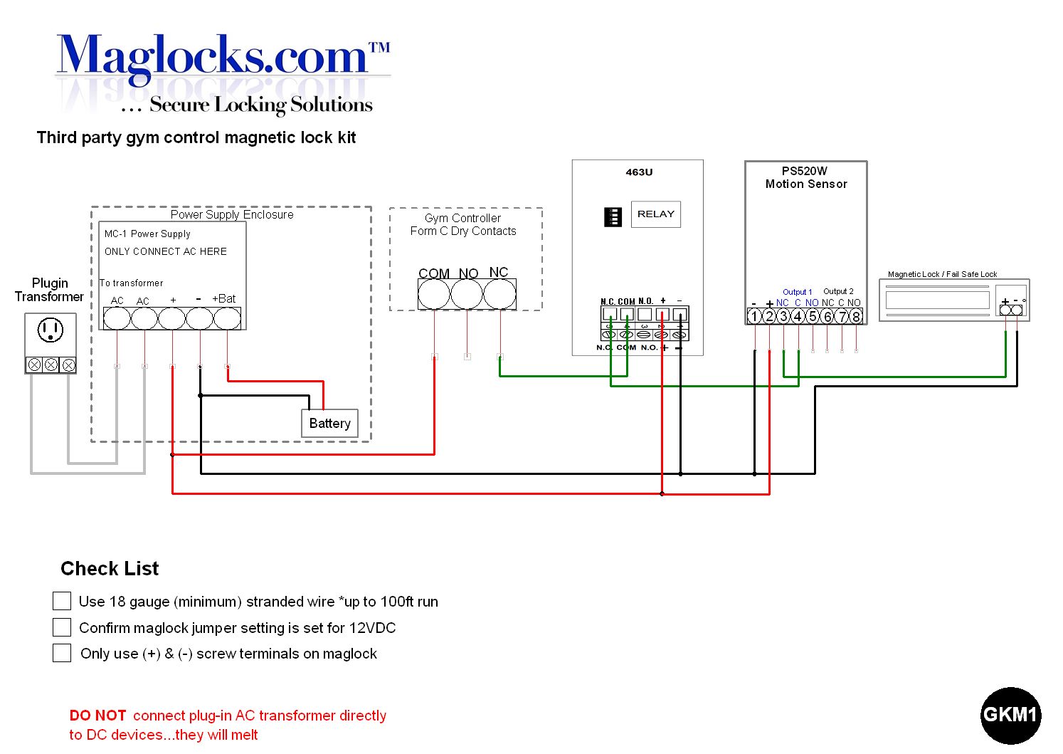
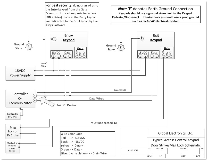
WIRING AND TECHNICAL INFORMATION Form 39873 2 10/13/2003 MBS: (Magnetic Bond Sensor - indicates lock status, shown unlocked: changes state when a good magnetic bond is indicated) WHITE: C. WHITE: N.O. (RATING:0.250A@30VDC) NOTE: POLARITY IN THIS CASE DOES NOT MATTER. IT IS SHOWN AS A SUG-GESTION TO KEEP WIRING WITHIN A SYSTEM CONSISTENT. MBS ... locknetics maglock wiring diagram - What is a Wiring Diagram? A wiring diagram is an easy visual representation with the physical connections and physical layout of the electrical system or circuit. It shows how a electrical wires are interconnected which enable it to also show where fixtures and components might be connected to the system. 1 SPDT voltage output . The SDC ACM-1 Access Control Module is an magnetic lock or electric strike. . (for two door or tamdem applications). The next step is to have a 'fail safe' method of cutting the power to the lock to ensure the Where access control equipment is fitted to a fire escape door which includes an Wiring Break glass units and fire alarm interfaces The FIB provides a switching ... How to wire a magnetic lock with, backup battery, exit button and key switch. This and other diagram and tutorials are available on our website at; www.there...
6. Continue to fasten mounting plate to heading using remaining screws. Then, reassemble maglock assembly to mounting plate. 7. Route the enclosed wiring harness through the rectangular hole in the mounting plate. Make the electrical connection as shown below. 8. Make sure that armature/strike plate can be shaken slightly.
Locknetics Maglock Wiring Diagram. Wiring Diagram 74 views. Wiring Diagram for A House. Wiring Diagram 175 views. Cushman Turf Truckster Wiring Diagram. Wiring Diagram 1036 views. Search for: Recent Posts. 1 Xbox 360 Wireless Controller Wiring Diagram. 2 Wiring A Switch Diagram. 3 Guitar Amp Wiring Diagram.
17.09.2018 17.09.2018 1 Comments on Locknetics Maglock Wiring Diagram. Locknetics offers many sizes of each. Herculite door brack- connections (see wiring instructions on next page). Install circuit board(s) (if OUTSWINGING MAGNETIC LOCK with AVS SEE DIAGRAMS ABOVE. PC BOARD.
Discover the Simplicity of Locknetics Backed by the strength and promise of Allegion, Locknetics provides electromechanical hardware for access control solutions. Designed to fit the challenges of everyday, on the job applications, the Locknetics portfolio, with electric strikes, electro-magnetic locks and access control accessories, offers ...
a wiring diagram is a streamlined standard pictorial depiction of an electrical circuit. the kit meets a variety of building, fire and life safety codes. locknetics products. the device will create a 15 second delay with audible alarm when an unauthorized person tries to ex. mag locks on double egress doors.
locknetics maglock wiring diagram - Architectural electrical wiring diagrams show the approximate locations and interconnections of receptacles, illumination, and long-term electric solutions in a building. Adjoining cable routes may be revealed roughly, where particular receptacles or fixtures should get on a typical circuit.
- WIRING INSTRUCTIONS— Magnetic lock or fail safe strike with button, keypad, maintained button and remote receiver. wired in series Power Supply for fail safe strikes and magnetic locks should be DC. If this is not available you may use an AC power source and wire inline a "Full Wave Bridge" rectifier. This will conver t the AC to DC.
Locknetics Maglock Wiring Diagram This manual covers the complete installation and wiring instructions for the following. GF . Make final wiring connections (see Wiring Diagram: on page LOCKNETICS. M I MN MORTISED MAGNETIC LOCK. INSTALLATION AND WIRING INSTRUCTIONS. Birch Street, Forestville, CT. Wiring should be protected by conduit.
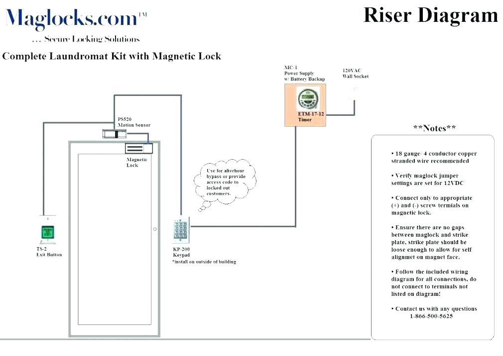
Wiring the Electromagnetic Locking System. In the simple diagram above, you can see that the electricity travels in an unbroken loop. It starts at the "+" (positive) terminal of the power supply, travels through the exit and entry switches, into the positive terminal of the magnetic lock, and out through the negative (-) terminal of the mag back in through the negative terminal of the power ...
39 grandfather clock oiling diagram. Use a small pair of pliers to remove it, if necessary. Place a small amount of clock oil onto the gears within the clock, and oil the clock mechanisms once every three years for maintenance. Examine the weights on your Tempus Fugit Grandfather clock. Carefully remove the pendulum -- which is the piece that ...
Whole House Generator Transfer Switch Wiring Diagram Download. whole house generator transfer switch wiring diagram - A Beginner s Guide to Circuit Diagrams An initial consider a circuit layout could be complex, yet if you could review a subway map, you could review schematics. The purpose is the very same: getting from factor A to point B. Literally,…
For double doors without a center mullion, the Securitron DM62 Magnalock supplies two model M62 Magnalocks in a single, brushed stainless steel housing.
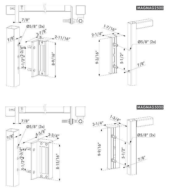
Wiring for the electromagnet must enter the top of the unit through the wire access hole drilled in the frame header (see template). Be certain provisions can be made to bring the wire through the header into the top of the unit. Frame conditions may require the use of filler plates and/or angle brackets. These items are available from Locknetics.
















0 Response to "42 locknetics maglock wiring diagram"
Post a Comment