39 draw a ray diagram of the lens system you set up in c6
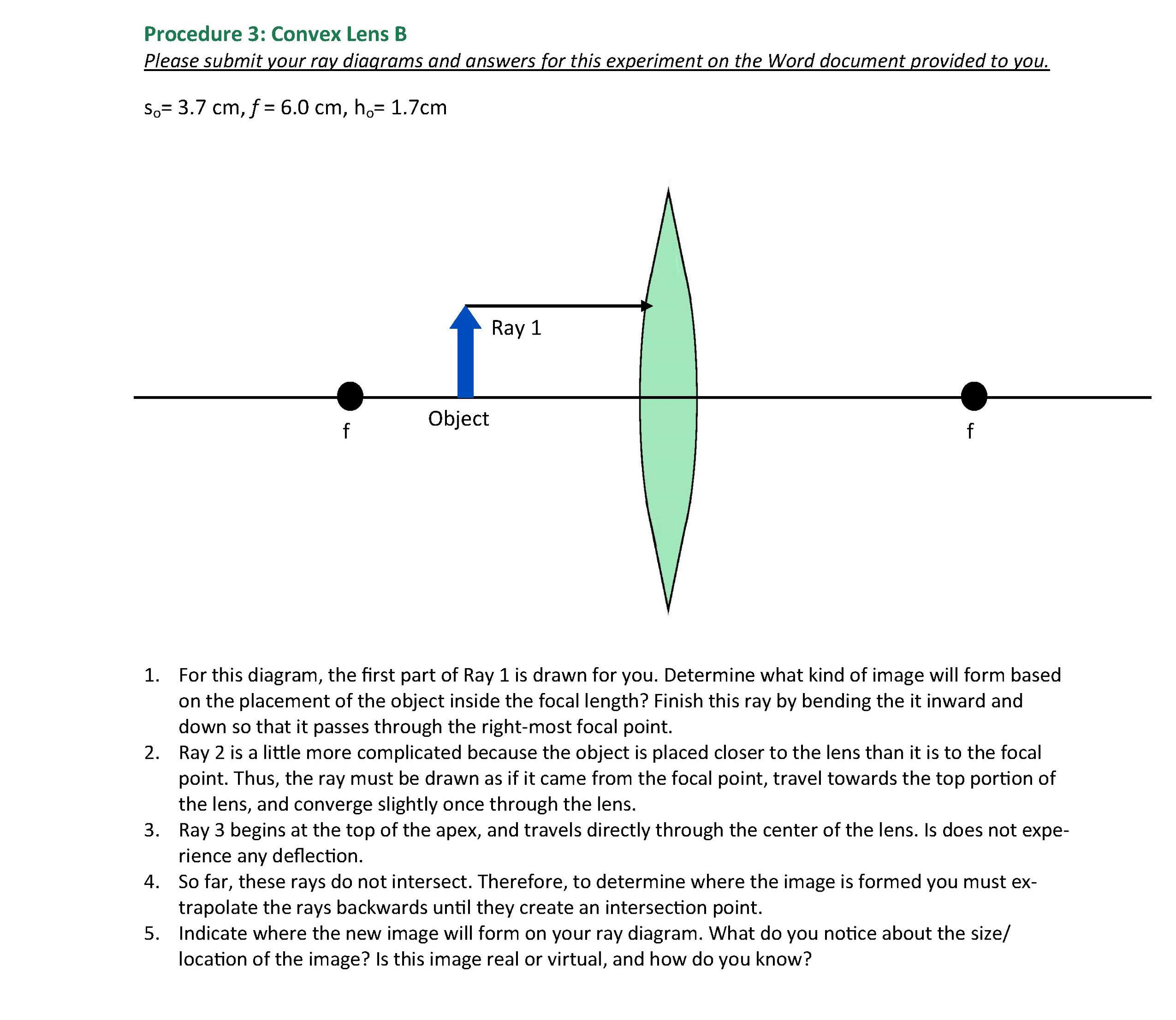
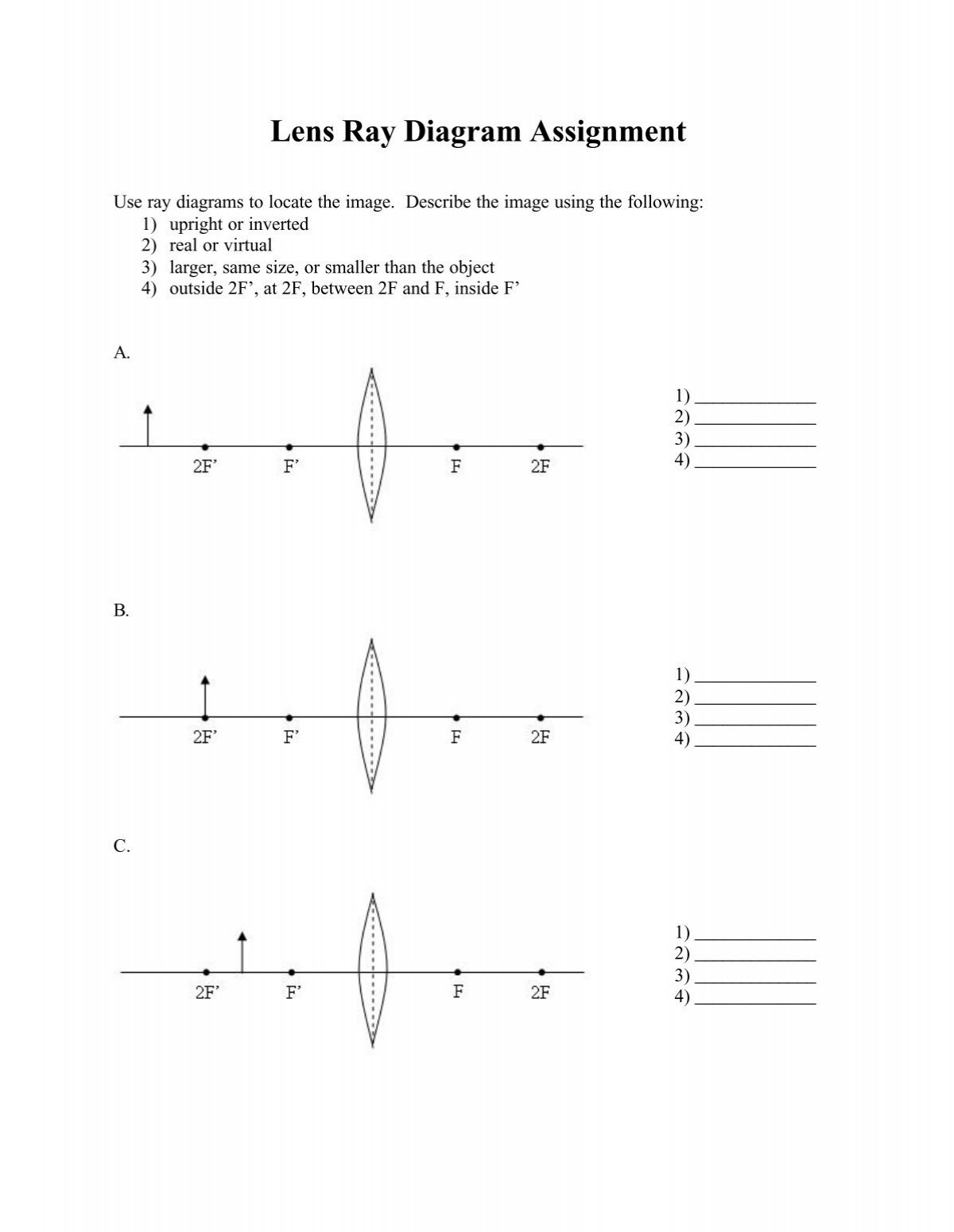
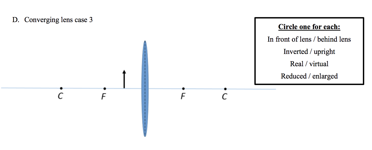
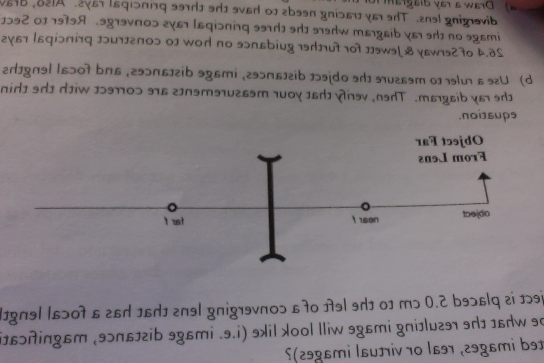
10.a.Draw a ray diagram of the lens system as it should look at the end of Step C6 (the set up for forming the image of areal image).Draw the ray diagram roughly to scale and label all lengths (based on the values given in the dataset.)b. Describe in one sentence the final image as accurately as possible (characterize its type and its ... Step-by-Step Method for Drawing Ray Diagrams. The method of drawing ray diagrams for double convex lens is described below. The description is applied to the task of drawing a ray diagram for an object located beyond the 2F point of a double convex lens. 1. Pick a point on the top of the object and draw three incident rays traveling towards the lens.
dot diagram for phosphorus; draw a ray diagram of the lens system you set up in c6; dry cell battery diagram; dryer motor wiring diagram; duraspark wiring diagram; e30 wiring diagram; e39 belt diagram; ear diagram with labels; eaton 3 way switch wiring diagram; ebay wireless winch remote wiring diagram; echo srm 225 parts diagram; electrolux ...
Draw a ray diagram of the lens system you set up in c6
Designed with you in mind, LG products offer innovative solutions to make life good. With intuitive, responsive controls, sleek, stylish designs, and eco-friendly features, our collection gives you the power to do more at home and on the go. Nov 18, 2021 · First, we draw a ray parallel to principal axis. So, it passes through focus after refraction. We draw another ray which passes through Optical Center. So, the ray will go through without any deviation. Where both refracted rays meet is point A'. And the image formed is A'B'. This image is formed between beyond 2F 2. Draw a ray diagram of the lens system as it should look at the end of Step C6 (the setup for forming the image of a real image). Draw the ray diagram roughly to scale and label all lengths (based on the values given in the dataset.) b.
Draw a ray diagram of the lens system you set up in c6. Enter the email address you signed up with and we'll email you a reset link. Draw a ray diagram of the lens system as it should look at the end of Step C6 (the set up for forming the image of areal image).Draw the ray diagram roughly to scale and label all lengths (based on the values given in the data set.) b. Describe in one sentence the final image as accurately as possible (characterize its type and its appearance ... We ship you all installation materials ... Start with a new lens, and enter system and surface ... Analysis>Diagnostics>Ray Aberration Curves or OPD.39 pages Defining the lens system data . ... Extending the rays in the lens drawing . ... the diagram, click on the Setup Window/Toolbar icon in the.135 pages
on other side of lens until you get an image on it. 5.Measure the distance of image from the v stand of lens (image distance 'v') and also measure the distance between candle and stand of lens (object distance 'u'). 4QDraw ray diagrams for the following positions and explain the nature and . position of image. [AS6] A) Object placed at c2 Jan 14, 2022 · Step-by-Step Method for Drawing Ray Diagrams. The method of drawing ray diagrams for double convex lens is described below. The description is applied to the task of drawing a ray diagram for an object located beyond the 2F point of a double convex lens. 1. Pick a point on the top of the object and draw three incident rays traveling towards the ... Suggestion: Drawing a ray diagram would be helpful. ... Suggestion: Draw a top-view diagram to ... lens is set up with its axis pointing toward the light-.264 pagesMissing: c6 | Must include: c6 Nov 21, 2007 · This Demonstration lets you visualize the ray diagrams for converging and diverging lenses. By manipulating the object and lens locations, you can create real or virtual images. The rays parallel to the principal axis and the ray through the center of the lens are drawn.Locators allow you to drag both the object and the lens. You can change the focal length using a slider. The degree of magnificat
To obtain the object distance/image distance, you need to take the difference between these values) C6:The meter reading for the setup of the real image of the ...4 answers · Top answer: So discussion belongs to the chapter lens and optical instrument and which says that a line ... Construct ray diagrams and use thin lens and mirror equations to locate the images formed by lenses and mirrors. Only transverse waves can be polarized. You can also from a light is very high, properties of light worksheet answers ebook, in intensity of plant and. Analyze scientific data by using, interpreting, and comparing numbers in several ... Free Online CBSE Class Notes, NCERT Solutions, Self Study material for Class 6, Class 7, Class 8, Class 9, Class 10, Class 11 and Class 12 dodge dakota tail light wiring diagram; dot diagram for phosphorus; draw a ray diagram of the lens system you set up in c6; dry cell battery diagram; e30 wiring diagram; e39 belt diagram; eaton 3 way switch wiring diagram; ebay wireless winch remote wiring diagram; electrolux washer parts diagram; electron dot diagram for rubidium; elements and ...
Draw a ray diagram of the lens system as it should look at the end of Step C6 (the setup for forming the image of a real image). Draw the ray diagram roughly to scale and label all lengths (based on the values given in the dataset.) b.
Nov 18, 2021 · First, we draw a ray parallel to principal axis. So, it passes through focus after refraction. We draw another ray which passes through Optical Center. So, the ray will go through without any deviation. Where both refracted rays meet is point A'. And the image formed is A'B'. This image is formed between beyond 2F 2.
Designed with you in mind, LG products offer innovative solutions to make life good. With intuitive, responsive controls, sleek, stylish designs, and eco-friendly features, our collection gives you the power to do more at home and on the go.



![Solved 10. (1.5 pts] {Section C} a. Draw a ray diagram of ...](https://media.cheggcdn.com/media/74c/74c29763-952b-4550-947f-37f0d6c3fb35/php5yYACe)





0 Response to "39 draw a ray diagram of the lens system you set up in c6"
Post a Comment