39 draw the shear diagram for the beam. 7.93
Feb 04, 2022 · 7.79 draw the shear diagram for the beam. Nov 24, 2016 This question can be found in Engineering Mechanics: Statics (SI edition), 13th edition, chapter 3, question 3-43. Leave a comment Cancel reply Your email address will ⋯ Computing the mass and weight of a man on earth and on the 7-88. Engineering Civil Engineering Q&A Library Derive the expressions for V and M and draw the shear force and bending moment diagrams. Neglect the weight of the beam. Wo Derive the expressions for V and M and draw the shear force and bending moment diagrams. Neglect the weight of the beam. 120 lb/ft B 8 ft 6 ft
Draw the shear and moment diagrams for the overhang beam. SOLUTION The maximum span moment occurs at the position where shear is equal to zero within the region of the beam.This location can be obtained using the method of sections. By setting Fig. b, we have Ans.
Draw the shear diagram for the beam. 7.93
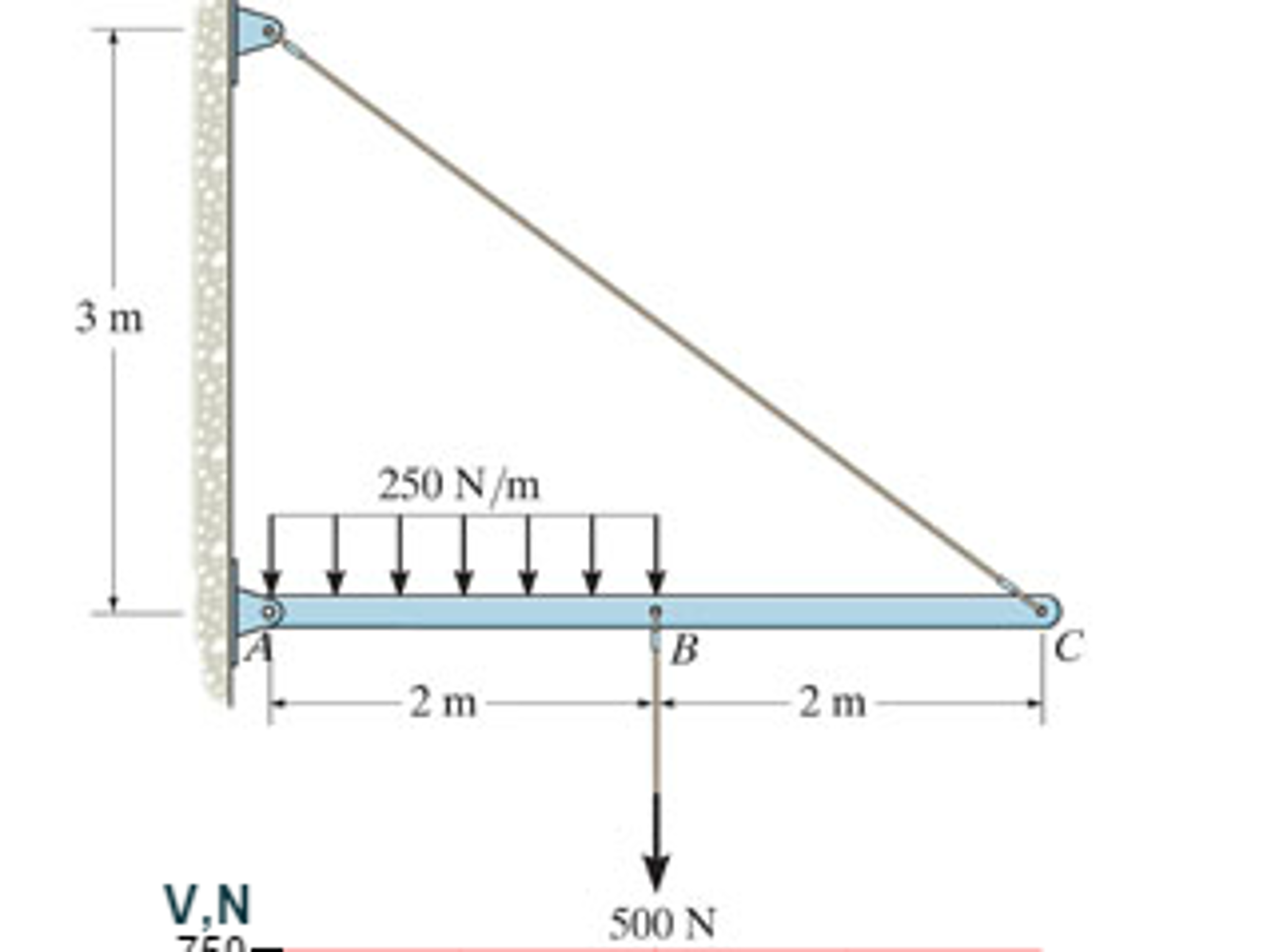
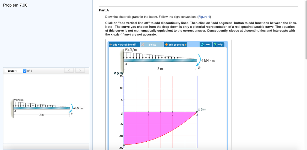
•7–93. Determine the force P needed to hold the cable in the position shown, i.e., so segment BC remains A E horizontal. Also, compute the sag yB and the maximum yB 3m tension in the cable. ... Draw the shear and moment diagrams for beam CD. Solved: 7-93. Draw The Shear And Moment Diagrams For The B... | Chegg.com. engineering. mechanical engineering. mechanical engineering questions and answers. 7-93. Draw The Shear And Moment Diagrams For The Beam 3 KN/m Prob. 7-93. Question: 7-93. Draw The Shear And Moment Diagrams For The Beam 3 KN/m Prob. 7-93. Transcribed image text: Problem 7.93 〈 3016 〉| Draw the shear diagram for the beam. Follow the sign convention. (Figure 1) Click on "add vertical line ...
Draw the shear diagram for the beam. 7.93. Solution for 2 kip /ft 1 kip/ft -15 ft - Prob. 7-93. Q: The procedure of designing spread footing foundations on the basis of field exploration data (standa... A: The footing takes all the load coming from slab beam and column thus being the most important elemen... 7-22 Determine the internal normal force, shear force, and moment at points D and E in the overhang beam. Point D is located just to the left of the roller support at B, where the couple moment acts. Exercises Corresponding to Section 7.2 7-46 Draw the shear and moment diagrams for the beam (a) in terms shear and moment diagrams for the beam. 11/09/2021 · > Engineering Mechanics Statics 13th Edition ( Solutions Manual) R. 76. 79 10. The distributed load is the slope of the shear diagram and each point load represents a jump in the shear diagram. 9 C+ 73. 7.79 draw the shear diagram for the beam. In the Eighth Edition of Answer to Solved Draw the shear diagram for the beam. Draw the moment.
7–93. Draw the shear and moment diagrams for the beam. Who are the experts? Experts are tested by Chegg as specialists in their subject area. We review their content and use your feedback to keep the quality high. Transcribed image text: 7-93. Draw the shear and moment diagrams for the beam. 6 kN 12 kN/m А В , 6 m 3 m. 7-88. Draw the shear and moment diagrams for the beam.... 7-89. The shaft is supported by a smooth thrust bearing at A and a smooth journal bearing at B. Draw the shear and moment diagrams... 7-90. Draw the shear and moment diagrams for the overhang beam.... 7-91. Draw the shear and moment diagrams for the beam.... 7-92. The beam consists of ... Problem 7.93 Click on add discontinuity to add discontinuity lines. Then click on add segment. Part B Draw the moment diagram for the beam Click on add ... Determine from the beam and the loads shown: Reactions on supports. Shear force diagram. Bending moment diagram. The neutral axis. The moment of inertia. The first moment of area. Consider a section located 1100 mm from point A. Determine: The maximum normal stress of the section. The maximum shear stress of the section. Deflection. The slope
Draw the shear and moment diagrams for the 2000 lb 500 lb/ ft A B 9 ft 7–82. 9 ft Draw the shear and moment diagrams for the beam. w0 A B L 629 L 7 Solutions 44918 1/27/09 10:39 AM Page 630 © 2010 Pearson Education, Inc., Upper Saddle River, NJ. 7.79 draw the shear diagram for the beam. This question can be found in Engineering Mechanics: Statics (SI edition), 13th edition, chapter 2, question 2-19. Leave a comment Cancel reply Your … Course Help Online - Have your academic paper written by a Christiaan Huygens was born on 14 April 1629 in The Hague, into a rich and For the given simply supported beam: If P=84 N/m, W=84 N/m, L1=7.93 meter, L2=1.33 meter A L1 L2 Calculate the vertical reaction at A. check_circle Expert Answer. ... Draw the shear and bending moment diagrams of the beams loaded as shown in the figures below. Round ... Problem 7.93. Draw the shear diagram for the beam. Click on add discontinuity to add discontinuity lines. Show transcribed image text ...
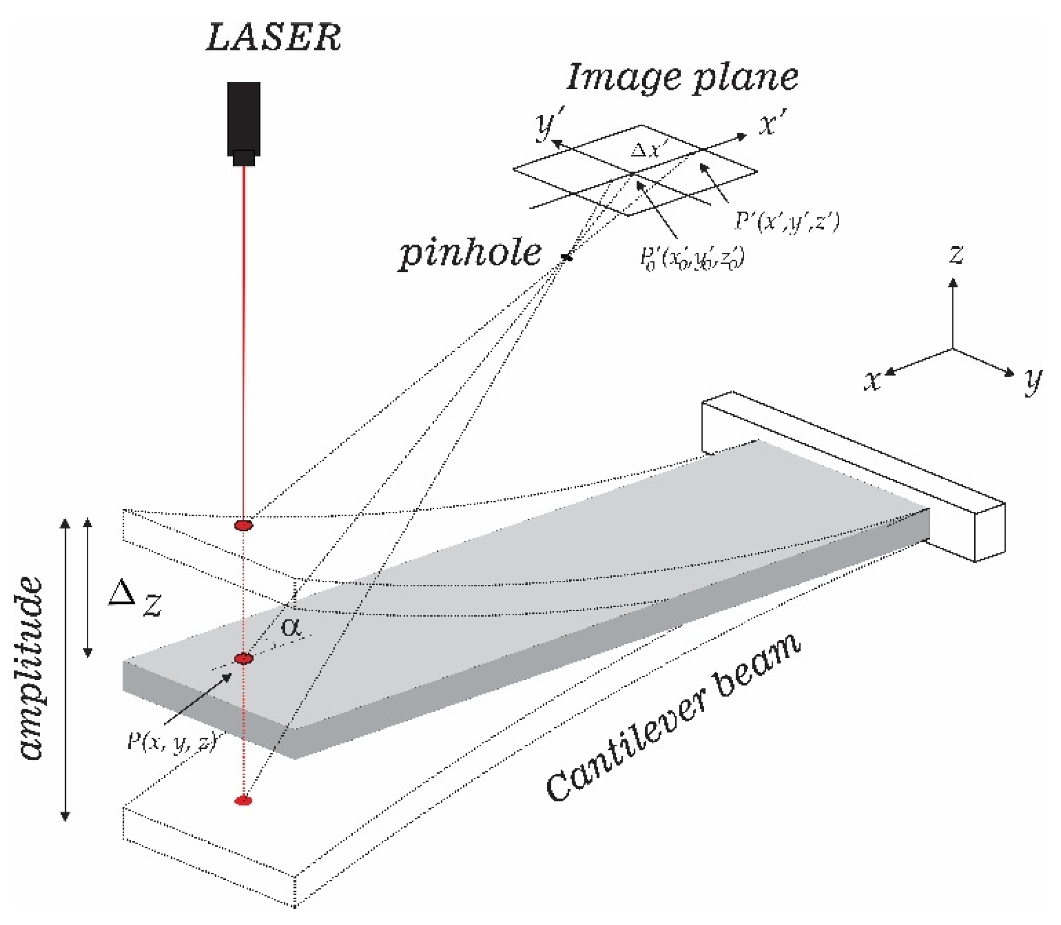
Symmetry | Free Full-Text | Vibration Measurement Using Laser ...
4 kip / ft 20 kip 20 kip 15 ft A B 30 ft 15 ft Prob. 7-73 7-74. Draw the shear and moment diagrams for the simply-supported beam. w 0 2 w 0 L / 2 L / 2 A B Prob. 7-74 7-75. Draw the shear and moment diagrams for the beam. The support at A offers no resistance to vertical load. L A B w 0 Prob. 7-75 PROBLEMS 7-70.
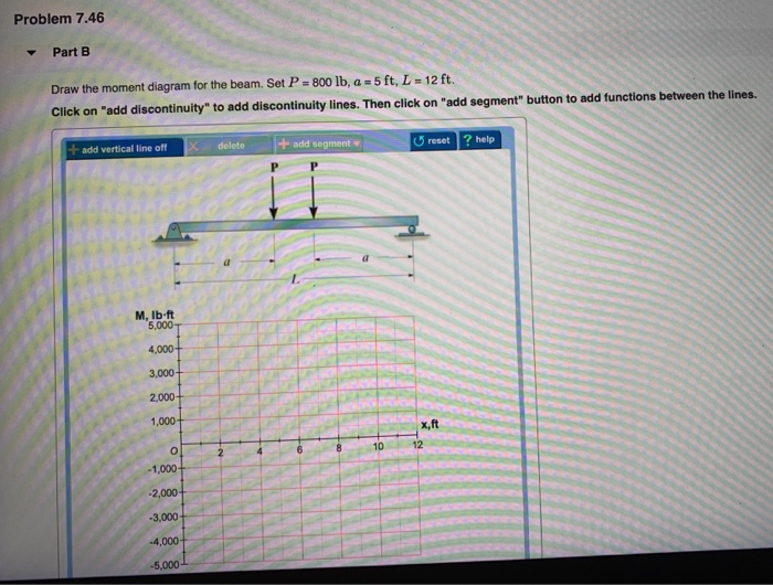
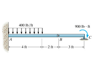
Solved Problem 7.46 12 ft Draw the shear diagram for the ...
Draw the shear and moment diagrams for the beam. Problem 7–90 7–91. The beam consists of two segments pin connected at B. Draw the shear and moment diagrams for the beam. Problem 7–91 *7–92. Draw the shear and moment diagrams for the beam. Problem 7–92 7–93. Draw the shear and moment diagrams for the beam. Problem 7–93

CHAPTER OBJECTIVES Determine stress in members caused by ...
For the beam and loading shown, (a) draw the shear and bending-moment diagrams, (b) determine the maximum absolute values of the shear and bending moment.

Relative influences of cracking and connection yield on ...
7.79 draw the shear diagram for the beam. Statics chapter 5 solutions Engineering Mechanics: Statics 14th ed Hibbeler
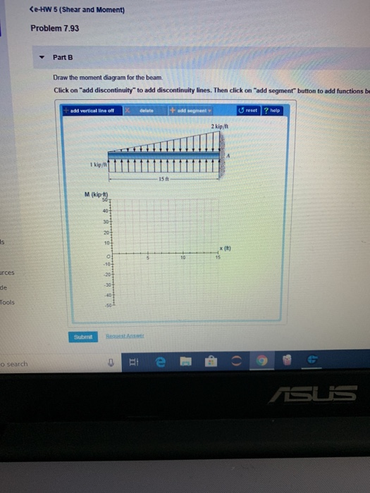
Solved Problem 7.93 Draw the shear diagram for the beam ...
Draw the shear and moment diagrams for the beam. StudySoup. Log in Sign Up. ... Problem 7-93. Draw the shear and moment diagrams for the beam. Step-by-Step Solution: Step 1 of 3. Chemical Tools: Experimentation and Measurement • Recognize the seven basic SI units of measure. • Give the numerical equivalent of the common metric prefixes used ...
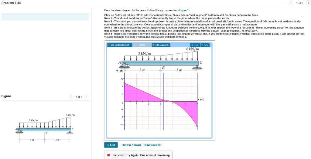
Solved Draw the shear diagram for the beam. Follow the sign ...
Draw the shear and moment diagrams for the beam. Solution. 5 (1 Ratings ) Solved. Electrical Engineering 2 Years Ago 108 Views. This Question has Been Answered! View Solution. Related Answers 7-93. Draw the shear and moment diagrams for the beam. ... 7-94. Determine the tension in each segment of the cable and the cable's total length. Set ...
Solved Problem 7.75 Part A Draw the shear | Chegg.com
2010 · The details of dissociation, however, are still subject to debate (figure 7) [79, 80]. 1-197 16. Draw the shear and moment diagrams for the cantilevered beam. 1-13 16. 0. Draw the shear and moment diagrams for the double O"erhnng beam.Trend Hunter's long-awaited 2022 Trend Report research is ready -- and this year it's free!
Solved a) Draw the shear diagram for the beam. b) Draw ...
7-93 for Seismic Performance Cate-gories (A) through (D). 3. The manufacturer shall verify that the unit provides continuous load paths with adequate strength and stiffness to transfer all forces from the point of application to the point of resistance at the foundation. The design and detailing of the unit shall comply with Section 9.3.6 of ASCE
Solutions Mannual statics bedfort second section
The distance traveled by the latter beam in excess of the first is twice the thickness of the film and its equivalent air path is: 2 nt where n is the refractive index and t is the thickness of Oct 26, 2021 · engineering-mechanics-statics-rc-hibbeler-12th-edition-solution-manual-pdf 2/3 Downloaded from 66. 79 draw the shear diagram for the beam.
Solved Draw the shear and moment diagram for the beam ...
Question: 7-93. Draw the shear and moment diagrams for the beam. 2 kip/ft 1 kip/ft 1s in Prob. 7-93 Draw the shear and moment diagrams for the beam. 2 kip/ft 1 kip/ft 1s in Prob. 7-93 This problem has been solved!

Problem 7.56 4 of 4 Part A Draw the shear diagram for the ...
Exercises Corresponding to Section 7.2 7-46 Draw the shear and moment diagrams for the beam (a) in terms of the parameters shown; (b) set P = 800 lb, a = 5 ft, L = 12 ft. F 7-8 Determine the shear and moment as a function of x then draw the shear and moment diagrams.,
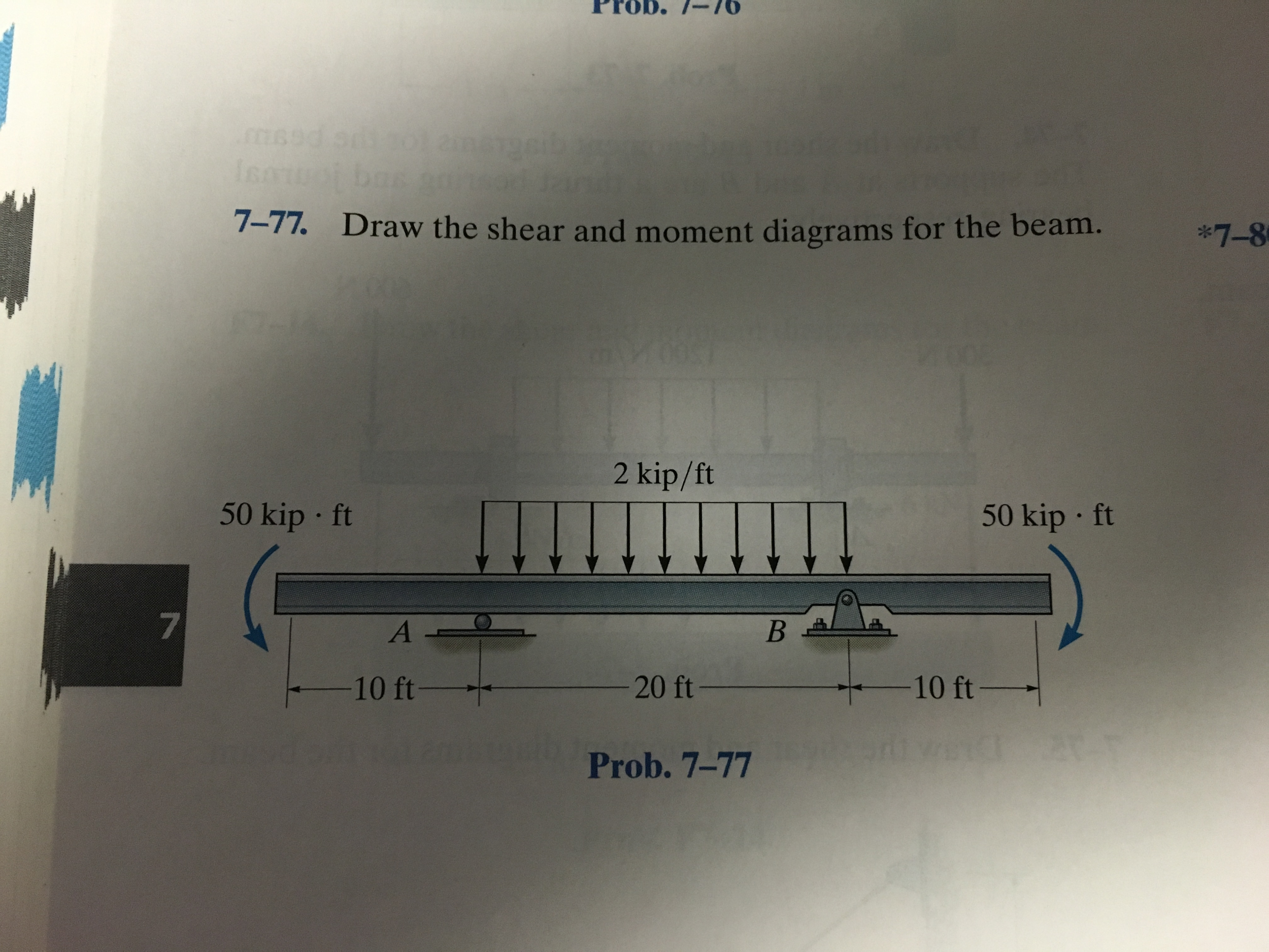
Solved 7-77 Draw the shear and moment diagrams for the beam ...
See the answer See the answer done loading. 7.93 Draw the shear diagram for the beam. Expert Answer. Who are the experts? Experts are tested by Chegg as specialists in their subject area. We review their content and use your feedback to keep the quality high. 100% (10 ratings)
Buildings | Free Full-Text | Experimental Investigation of ...
The answer to “Draw the shear and moment diagrams for the beam. 15 ft 1 kip/ft NLS/ft A Prob. 793” is broken down into a number of easy to follow steps, and 17 words. The full step-by-step solution to problem: 7-93 from chapter: 7 was answered by , our top Engineering and Tech solution expert on 11/10/17, 05:25PM.
Index 450-450 Series Florida Slab Beams
dissociation, however, are still subject to debate (figure 7) [79, 80]. 1-197 16. Draw the shear and moment diagrams for the cantilevered beam. 1-13 16. 0. Draw the shear and moment diagrams for the double O"erhnng beam. (PDF) Engineering Mechanics Statics 13th Edition-Solution Description For Statics Courses. A Proven
Design and investigation of the fiber Bragg grating pressure ...
Solution for Draw the shear and moment diagrams for the following beams show your solution. menu. Products. Subjects. Business. Accounting. Economics. Finance. Leadership. Management ... Draw the shear and moment diagrams for the following beams show your solution. close. Start your trial now! First week only $4.99! arrow_forward.
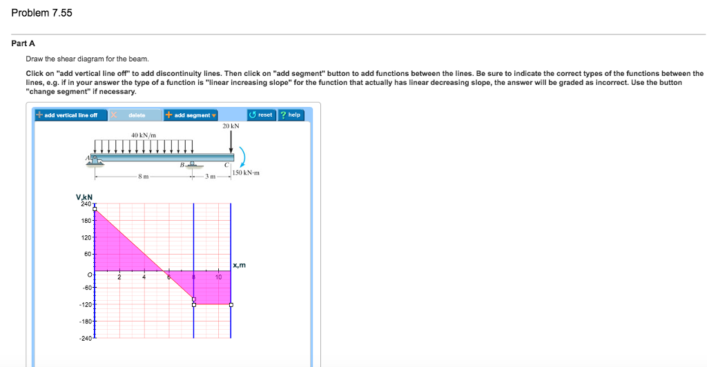
Solved Problem 7.55 Part A Draw the shear diagram for the ...
Transcribed image text: Problem 7.93 Draw the shear diagram for the beam Click on add discontinuity to add discontinuity lines. Then click on "add segment" ...
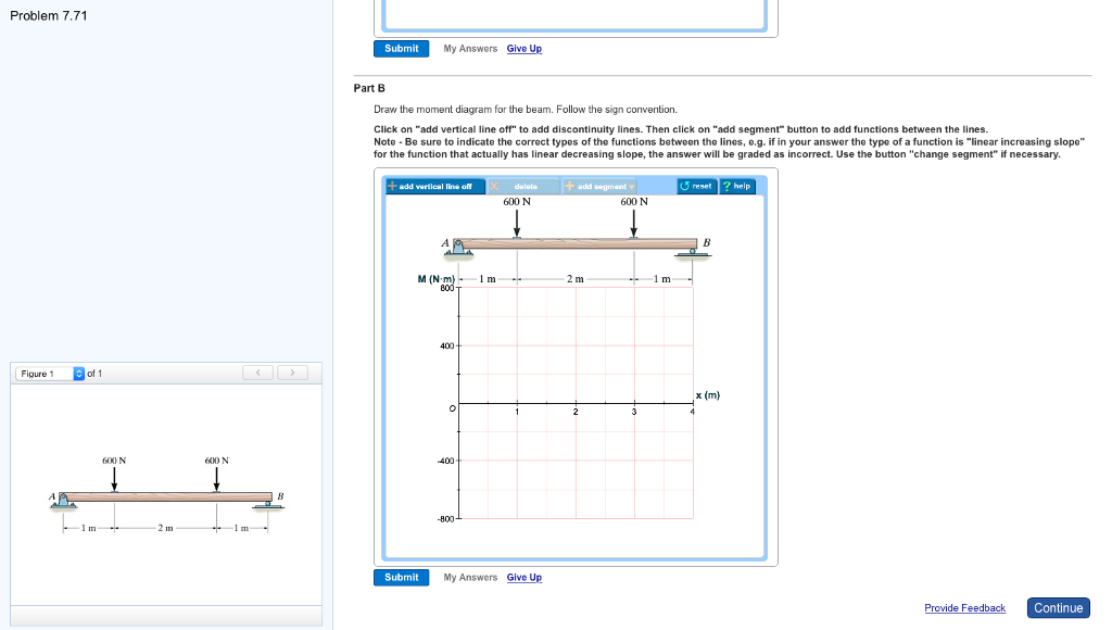
Solved Problem 7.71 Part A Draw the shear diagram for the ...
7-85. Draw the shear and moment diagrams for the beam. ... 7-86. Draw the shear and moment diagrams for the beam.... 7-87. Draw the shear and moment diagrams for the beam.... 7-88. Draw the shear and moment diagrams for the beam.... 7-89. The shaft is supported by a smooth thrust bearing at A and a smooth journal bearing at B. Draw the ...
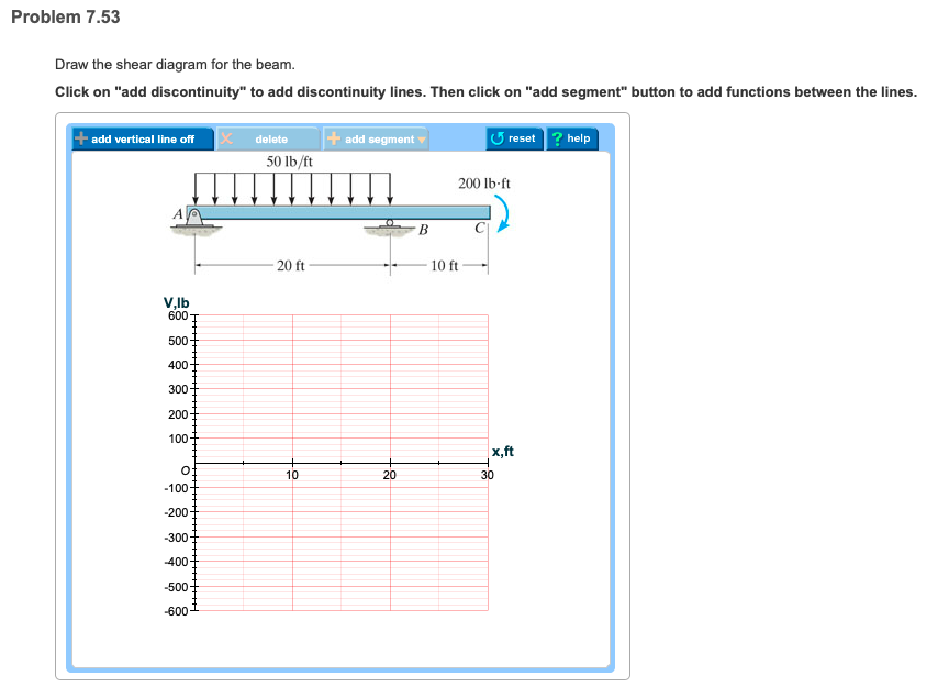
Solved Problem 7.53 Draw the shear diagram for the beam ...
Transcribed image text: Problem 7.93 〈 3016 〉| Draw the shear diagram for the beam. Follow the sign convention. (Figure 1) Click on "add vertical line ...
Solved Problem 7.70 Draw the shear diagram for the beam ...
Solved: 7-93. Draw The Shear And Moment Diagrams For The B... | Chegg.com. engineering. mechanical engineering. mechanical engineering questions and answers. 7-93. Draw The Shear And Moment Diagrams For The Beam 3 KN/m Prob. 7-93. Question: 7-93. Draw The Shear And Moment Diagrams For The Beam 3 KN/m Prob. 7-93.
Solved Draw the shear and the moment diagram for beam ABC if ...
•7–93. Determine the force P needed to hold the cable in the position shown, i.e., so segment BC remains A E horizontal. Also, compute the sag yB and the maximum yB 3m tension in the cable. ... Draw the shear and moment diagrams for beam CD.

Solved) - Draw the shear and bending moment diagrams for the ...

Statics 7.82 - Draw the shear and moment diagrams for the beam.
Eligible Facilities Request - Application Cover Letter - Base ...
Solved Problem 7.90. Draw the shear diagram for the beam ...
Solved problem 7.80 part A draw the shear diagram for the ...

Problem 7.56 4 of 4 Part A Draw the shear diagram for the ...
Applied Sciences | Free Full-Text | Calibration of Design ...

Experimental and numerical investigation of lateral torsional ...
Vibration | Free Full-Text | Nonintrusive Nonlinear Reduced ...
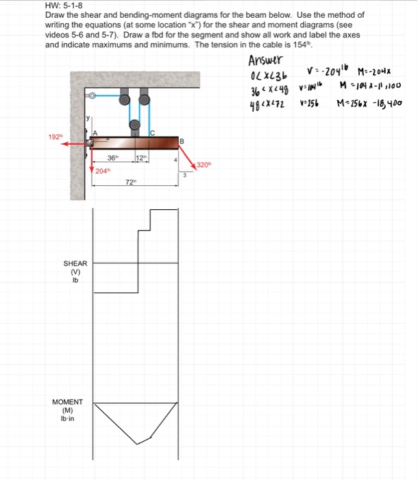
Solved HW: 5-1-8 Draw the shear and bending-moment diagrams ...

Draw the shear and moment diagrams for beam shown below ...

Drawing Shear and Moment Diagrams for Beam - YouTube

Drawing Shear and Moment Diagrams for Beam
Solved) - Draw the shear and moment diagrams for the beam ...

Experimental and Numerical investigations on the cyclic load ...

Symmetry | Free Full-Text | A High Temperature Solid Pressure ...
Bond Behavior of Cleaned Corroded Lap Spliced Beams Repaired ...
Solved Problem 7.53 - Enhanced - with Hints and Feedback < 8 ...
7.93 m Open TBM Shotcrete System Improvement and Innovation ...
0 Response to "39 draw the shear diagram for the beam. 7.93"
Post a Comment