39 rlc circuit phasor diagram
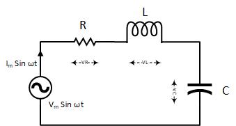
RLC Series circuit, phasor diagram with solved problem. An RLC series circuit contains all the three passive electrical components, Resistor Capacitor, and Inductor in series across an AC source. As there is only one path for current in a series combination, the current in all these components is the same in magnitude and phase. Phasor Diagram of Series RLC Circuit The phasor diagram of series RLC circuit is drawn by combining the phasor diagram of resistor, inductor and capacitor. Before doing so, one should understand the relationship between voltage and current in case of resistor, capacitor and inductor. Resistor
We recall from the previous tutorial about series RLC circuits that the voltage across a series combination is the phasor sum of V R, V L and V C. Then if at resonance the two reactances are equal and cancelling, the two voltages representing V L and V C must also be opposite and equal in value thereby cancelling each other out because with ...

Rlc circuit phasor diagram
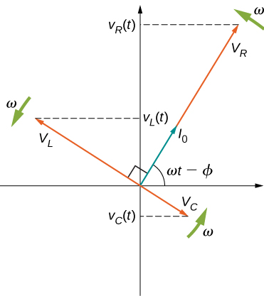
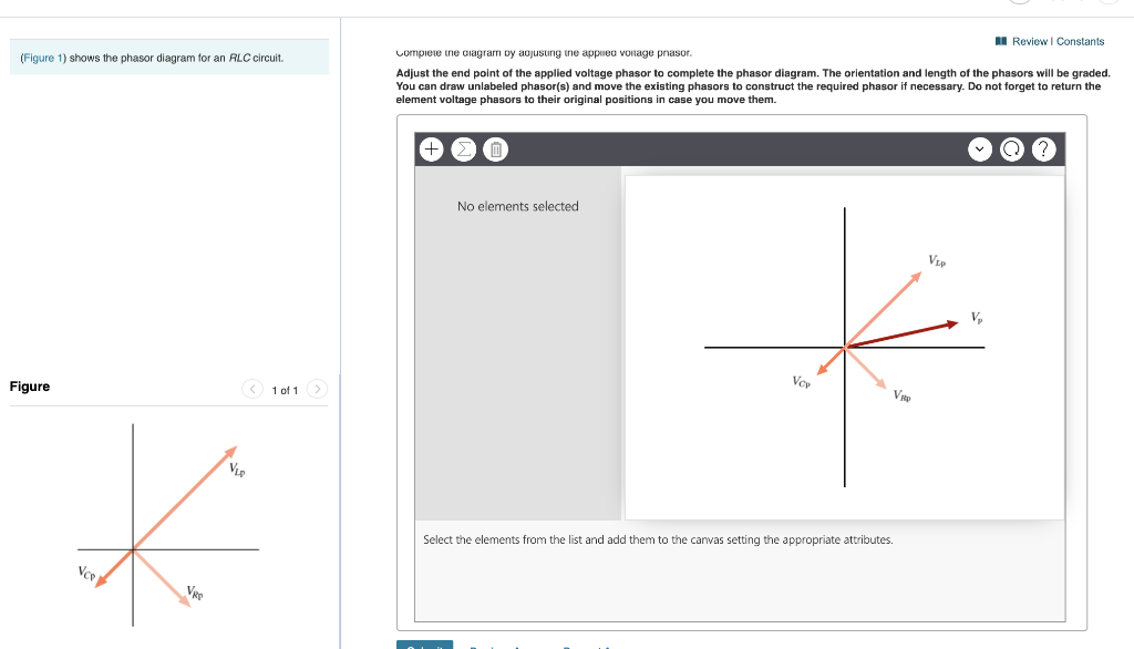
Combining the three independent phasors above and vectorially adding these voltages yields the phasor diagram for a series RLC circuit. Because the current flowing through the circuit is carried by all three circuit elements, we may use it as a reference vector, with the three voltage vectors shown at their corresponding angles in relation to it. Question: (Figure 1) shows the phasor diagram for an RLC circuit. Figure 1 of 1 VLE VCP VRP Complete the diagram by adjusting the applied voltage phasor. Adjust the end point of the applied voltage phasor to complete the phasor diagram. The orientation and length of the phasors will be graded. You can draw unlabeled phasor (s) and move the ... hello everyone, i have a question about rlc circuits. lets say i have a circuit like [this](https://imgur.com/a/9T4agpt) and id like to calculate the impedance. for the parallel part of the circuit the admittance would be Y=G+(1/jwL)+jwC and Y=1/Z so Z= 1\(G+(1/jwL)+jwC) . Now to get the total impedance i would just add Z=R , so Z= 1\(G+(1/jwL)+jwC)+R. How can I split this up into imaginary and real part?
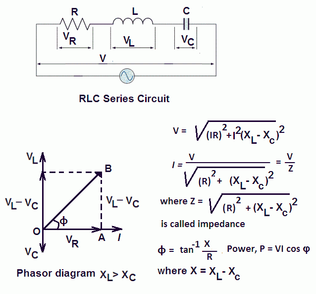
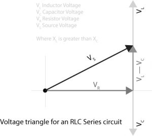
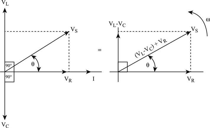
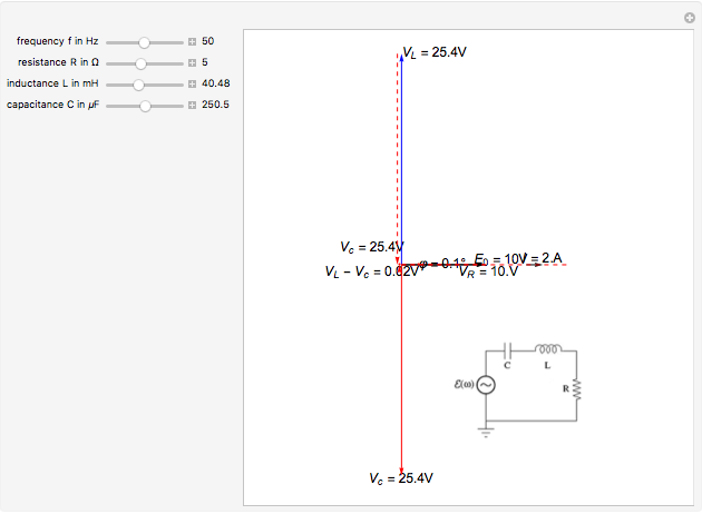
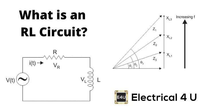
Rlc circuit phasor diagram. In the circuit diagram the RMS value of supply voltage is equal to the vector addition of the voltage across inductor (V L), voltage across resistance (V R) & voltage across capacitor (Vc ). The phasor diagram for the circuit can be drawn which shown the magnitude as well as the phase relationship between the various voltages (V R, V L, Vc, Vs ... Download Wolfram Player. This Demonstration shows a phasor diagram in an AC series RLC circuit. The circuit consists of a resistor with resistance , an inductor with inductance , and a capacitor with capacitance . The current in an RLC series circuit is determined by the differential equation. [more] , where and is the AC emf driving the circuit. Phasor diagram, Circuit Diagram, Formula | Alternating Current (AC) - Resonance in series RLC Circuit | 12th Physics : Electromagnetic Induction and Alternating Current Posted On : 24.03.2019 08:39 pm A series RLC circuit contains elements of resistance, inductance, and capacitance connected in series with an AC source, as shown in Figure 1. Figure 1 Series RLC circuit diagram. RLC Series Circuit Characteristics. The characteristics of the RLC series circuit can be summarized as follows: The current is the same through all components, but the voltage drops across the elements are out of ...
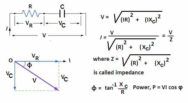
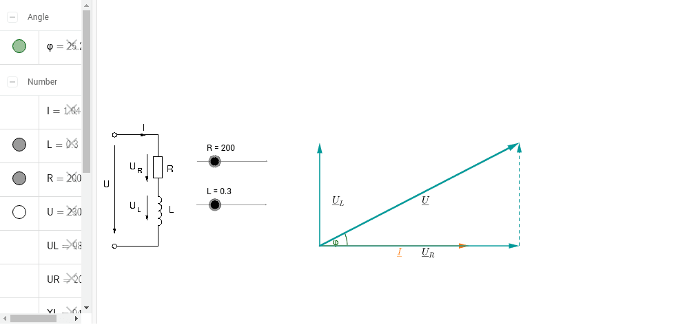
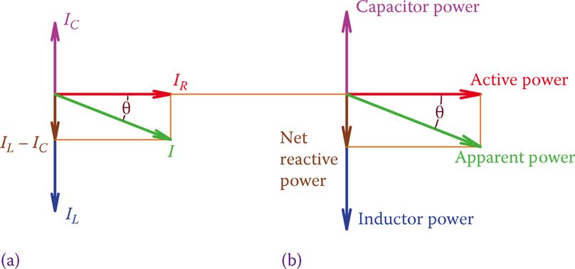
The phasor diagram of the series RLC circuit is then as shown in figure 2(a) Case 2: f The phasor diagram of series RLC circuit is drawn by combining the phasor diagram of resistor inductor and capacitor. P V L I LI dIdT So the entire power factor of the RL circuit is given by the power dissipated by the resistor along with the power absorbed by the inductor. This Demonstration shows a phasor diagram in an AC series RLC circuit. So I have to do a phasor diagrams for this 4 circuits. Number 2 and 4 I think I've done it correctly (but i can be wrong). Number 1 I just draw Uab and I2 and I3 and i dont know what to do next, and number 3 I just dont know how start it ( Ul or U) and how draw Uc and Ur. English is not my 1st language, but i think you will understand. Am I done 2 and 4 correctly? If not what did i do wrong? and how to make 1 and 3? [my diagrams](http://imgur.com/gallery/f6Dbpih) The phasor diagram of the RLC series circuit when the circuit is acting as an inductive circuit that means (V L >V C) is shown below and if (V L < V C) the circuit will behave as a capacitive circuit. Steps to draw the Phasor Diagram of the RLC Series Circuit Take current I as the reference as shown in the figure above An RLC circuit (also known as a resonant circuit, tuned circuit, or LCR circuit) is an electrical circuit consisting of a resistor (R), an inductor (L), and a capacitor (C), connected in series or in parallel. This configuration forms a harmonic oscillator. 2. RLC Series Circuit A phasor diagram for a parallel alternating current circuit is drawn analogically to that for a series circuit. We must take into account that in a parallel circuit, the voltage is the same across all elements, in contrast to a series circuit, where the same current flows through all elements.. How to draw the phasor diagram of a parallel RLC circuit: Draw the phasor of voltage along the x ... Parallel LC Circuit Impedance Calculator • Electrical, RF and ... CHAPTER 3 In many physical situations coupling can be created between two or more oscillatory systems. For instance, two pendulum clocks which are mounted on the same wall will be coupled by the flex. Phasor diagrams and Impedances PHASOR DIAGRAM OF RLC SERIES CIRCUIT As seen from the phasor diagram that Vₗ and Vc are 180 degree out of phase, they are direct opposite to each other. So effective voltage will be (Vₗ-Vc). Applied voltage is phasor sum of the voltage across resistance & effective voltage. V = √ { (Vr)² + (Vₗ -Vc)²} V = √ { (I*R)² + (I*Xₗ - I*Xc)²} Phasor - Wikipedia What Is Rlc Series Circuit Phasor Diagram Impedance Triangle Globe. The phasor diagram shows the phase difference between voltage an current. The LCR circuit analysis can be understood better in terms of phasors. Series RLC Circuit and RLC Series Circuit Analysis So we have R one r on equal Stan home and l equals 0.13 Henry and we also have ah capacitor in the circuit. See, it was 0.2 mil e fad So 0.0 seo two fad From here, the first thing we would have to find a find up capacity resistance equals one over Omega Psi. It was won over by F C F A 60 Hearts Mods bed by 0.123 to fad and that comes out to be 30.26 home. Series RLC Circuit (Circuit & Phasor Diagram) | Electrical4U The phasor diagram of series RLC circuit is drawn by combining the phasor diagram of resistor, inductor and capacitor. How is the sinusoidal response of a series RLC circuit determined? The series RLC circuit above has a single loop with the instantaneous current flowing through the loop being the same for each circuit element. RC | RLC | RL Series Circuits - your electrical guide Hi, I've been given an RL circuit and I need to draw a phasor diagram containing all the I's and V's using Itotal as the reference. The circuit has an inductor in series with 2 inductors in parallel and 2 resistors in parallel. Drawing the necessary phasors for the voltage is simple, but I'm not sure how to go about drawing the individual currents. To me it seems like I should draw the current through the inductor and the current through the resistor as legs of a right triangle with Itotal bein... Series RLC Circuit (Circuit & Phasor Diagram) | Electrical4U RLC Parallel circuit is the circuit in which all the components are connected in parallel across the alternating current source. In contrast to the RLC series circuit, the voltage drop across each component is common and that's why it is treated as a reference for phasor diagrams. Phasor Diagram - an overview | ScienceDirect Topics Phasor Diagrams are a graphical way of representing the magnitude and directional relationship between two or more alternating quantities Sinusoidal waveforms of the same frequency can have a Phase Difference between themselves which represents the angular difference of the two sinusoidal waveforms. Phasor Diagram - RL Series Circuit – GeoGebra The phasor diagram is shown in Figure 12.4(c). Example 12.6. A series RLC circuit consists of a resistance R = 10Ω, inductance L = 0.2H, and capacitance C = 0.2μF. Calculate the frequency of resonance. A10 volts sinusoidal voltage at the frequency of resonance is applied across the circuit. Draw the phasor diagram showing the value of each ... RC | RLC | RL Series Circuits - your electrical guide For the given circuit diagram calculate the RLC series circuit impedance, current, voltage across each component, and power factor. Also draw the phasor diagram of current and voltage, impedance triangle, and voltage triangle. First of all, let me calculate the total impedance with the following formula Resistance: R=12\Omega Phase angle of the electric current, circulating in the RLC ... PHY2054: Chapter 21 2 Voltage and Current in RLC Circuits ÎAC emf source: “driving frequency” f ÎIf circuit contains only R + emf source, current is simple ÎIf L and/or C present, current is notin phase with emf ÎZ, φshown later sin()m iI t I mm Z ε =−=ωφ ε=εω m sin t ω=2πf sin current amplitude() m iI tI mm R R ε ε == =ω Phasor Diagram of RL, RC and RLC Circuits (with Examples) The phasor diagram for a series RLC circuit for capacitive (left), inductive (center) and pure resistive (right) impedance. The voltage vectors on the diagram produce a rectangular voltage triangle with a hypotenuse V T, vertical leg V L -V C and horizontal leg V R. RLC Series circuit, phasor diagram with solved problem In this video, Phasor diagram representation of voltage and current for Series RC, RL and RLC circuit has been explained and the examples based on this phaso... RLC Series Circuits with AC – University Physics Volume 2 For drawing the phasor diagram for RLC series circuit, the current is taken as reference because, in series circuit the current in each element remains the same and the corresponding voltage vectors for each component are drawn in reference to common current vector. The Impedance for a Series RLC Circuit Series RLC Circuit (Circuit & Phasor Diagram) | Electrical4U Steps to draw a Phasor Diagram. The following steps are used to draw the phasor diagram of RC Series circuit. Take the current I (r.m.s value) as a reference vector; Voltage drop in resistance VR = IR is taken in phase with the current vector; Voltage drop in capacitive reactance VC = IXC is drawn 90 degrees behind the current vector, as ... Definition of The Series Rlc Circuit And Phasors | Chegg.com Hi guys I need help with this question: A series RC circuit consists of: 1) 0.1 uF (C1) 2) 0.22 uF (C2) 3) 2 resistors in parallel (100 ohm each) Assume that the applied voltage is 2V (phase angle 0°) and frequency of 15kHz. i) Calculate the total current and voltages across the resistors and capacitors. ii) Draw the voltage phasor diagram for this circuit. I have completed part (i) and have verified my answer. i) V(C1) = 1.30 ∠ -18.0° V, V(C2) = 595 ∠ -18... Chapter 12.3 - Phasor Diagram of Series RLC Circuit ... A series *RLC* circuit consists of a 99.0 Ω resistor, a 0.160 H inductor, and a 36.0 μF capacitor. It is attached to a 120 V/60 Hz power line. Part A What is the peak current I at this frequency? Part B What is the phase angle ϕ? Part C What is the average power loss? ​ I've followed and triple checked my professor's methods, but I just can't seem to wrap my head around it. Any help is appreciated. Phasor Diagram of an RC Circuit Vi(t) C Vo(t) VR Vm Im VC Hi guys I need help with this question: A series RC circuit consists of: 1. 0.1 uF (C1) 2. 0.22 uF (C2) 3. 2 resistors in parallel (100 ohm each) Assume that the applied voltage is 2V (phase angle 0°) and frequency of 15kHz. i) Calculate the total current and voltages across the resistors and capacitors. ii) Draw the voltage phasor diagram for this circuit. I have completed part (i) and have verified my answer. i) V(C1) = 1.30 ∠ -18.0° V, V(C2) = 595 ∠ -18.0° mV,... Phasor Diagram for Series RLC Circuits - Wolfram ... In an RLC series circuit a pure resistance (R), pure inductance (L) and a pure capacitor (C) are connected in series. To draw the phasor diagram of RLC series circuit, the current I (RMS value) is taken as the reference vector. The voltages across three components are represented in the phasor diagram by three phasors V R, V L and V C respectively. Solved Problem 2 The diagram below represents the phasor ... Parallel RL Circuit Phasor Diagram. The relationship between the voltage and currents in a parallel RL circuit is illustrated in the vector (phasor) diagram of Figure 2 and summarized as follows: The reference vector is labeled E and represents the voltage in the circuit, which is common to all elements. Offset problem in simulating current and voltage phase ... Network Theory: Phasor Diagram of Series RLC Circuit Topics discussed:1) Phasor diagram of series RLC circuit.2) Voltage triangle of series RLC circuit.3) Im... Circuit Phasor Diagram for Transformers - Wolfram ... RLC Series circuit As described above the overall phasor will look like below: Phasor diagram of current Vs voltage for resistor, inductor and capacitor for RLC series circuit From the above phasor diagram we know that, V 2 V 2 = (V R)2 + (V L - V c)2 ( V R) 2 + ( V L - V c) 2 —- (1) Solved (Figure 1) shows the phasor diagram for an RLC | Chegg.com hello everyone, i have a question about rlc circuits. lets say i have a circuit like [this](https://imgur.com/a/9T4agpt) and id like to calculate the impedance. for the parallel part of the circuit the admittance would be Y=G+(1/jwL)+jwC and Y=1/Z so Z= 1\(G+(1/jwL)+jwC) . Now to get the total impedance i would just add Z=R , so Z= 1\(G+(1/jwL)+jwC)+R. How can I split this up into imaginary and real part? Series RLC Circuit and RLC Series Circuit Analysis Question: (Figure 1) shows the phasor diagram for an RLC circuit. Figure 1 of 1 VLE VCP VRP Complete the diagram by adjusting the applied voltage phasor. Adjust the end point of the applied voltage phasor to complete the phasor diagram. The orientation and length of the phasors will be graded. You can draw unlabeled phasor (s) and move the ... Series RLC Circuit (Circuit & Phasor Diagram) | Electrical4U Combining the three independent phasors above and vectorially adding these voltages yields the phasor diagram for a series RLC circuit. Because the current flowing through the circuit is carried by all three circuit elements, we may use it as a reference vector, with the three voltage vectors shown at their corresponding angles in relation to it. RLC Series circuit, phasor diagram with solved problem Parallel RL Circuit | Phasor Diagram | Impedance & Power ... Current and Voltages Computations in Series RLC circuit Parallel RLC Circuit and RLC Parallel Circuit Analysis Phasor - Wikipedia Series LC Circuit | Phasor Diagram | Characteristics | Examples Parallel RLC Circuit: Analysis & Example Problems ... Additional Problems(80)Figure \"a\" shows a parallel RLC ... RL Series Circuit Analysis (Phasor Diagram, Examples ... LCR Series Circuits The phasor diagram for an RLC circuit driven by an AC source ... We shall examine three special cases of driven circuits Parallel RLC Circuit: What is it? (Circuit Analysis ...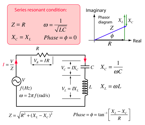


0 Response to "39 rlc circuit phasor diagram"
Post a Comment