41 buffer tank piping diagram
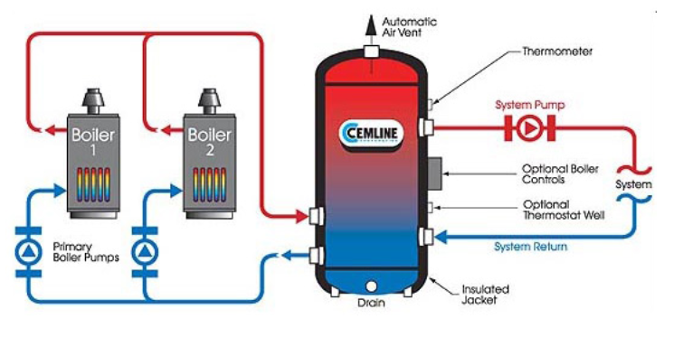
Tanks are built with the location and size of the openings to suit customer requirements. Flanged openings are 150# ANSI standard. Groove-end connections are furnished as required. 6" and below are schedule 40 pipe, 8" and above are schedule 30 pipe. An example of piping a buffer tank follows showing a water source heat pump application. In all applications note that the tank top fitting should be piped the distribution supply line to the air purger and vent. This way the tank will be self
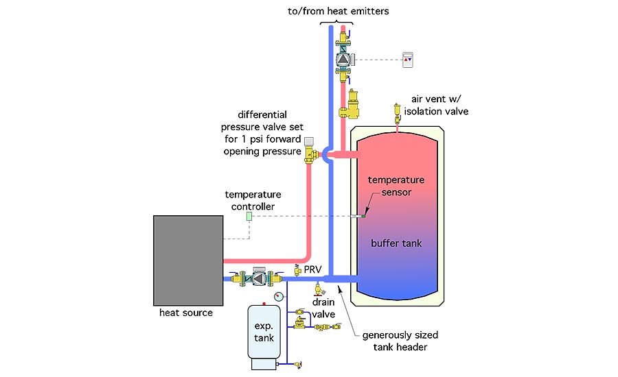
The buffer tank should be sized in accordance with the tank manufacturer’s instructions. B. Piping Buffer Tank Piping using 4 tank connections: For buffer tanks with four system connections, Figure 1.1 shows the recommended piping. Notice that the diagram shows a system sensor on the system supply pipe.
Buffer tank piping diagram
Product Drawings. Piping Diagram. Technical Papers. 3D-Drawings. Spec Sheets. CEMLINE® has made a series of typical piping arrangements for the Model Series: SEH, SSH, SWH, and USG. These drawings are in .DWG format or Adobe®Acrobat® (PDF) format. The Acrobat Reader is available free from Adobe. Note: Select the model and click on the ... A: Buffer tanks provide extra water volume in a closed chilled water system. Q:Are buffer tanks used in every chilled water system? A: No. Some systems have an adequate volume of water in them so the extra storage provided by the buffer tank is not required. Q: How do they work? A: The added capacity, provided by the tank, reduces is available for alternate piping configurations. When configured and piped correctly, Heat-flo hydronic buffer tanks can serve as both a thermal buffer and a hydraulic separator - allowing the heating or cooling source to be hydraulically decoupled from the distribution system. HYDRONIC BUFFER TANKS
Buffer tank piping diagram. Should I Consider A Buffer Tank Heating Help The Wall. Piping Diagram For Chilled Water Buffer Tank Ice Storage How and Why CALMAC April 20th 2019 – Additional savings are delivered from extended free cooling periods and the ef. Either the traditional buffer tank piping shown in Figure 1 or the alternate method shown in Figure 5 can be used. Multi-Purpose Tanks (MPT) Meets ASME Code Section VIII, Division 1 Taco's MPT style Multi-Purpose Tanks product line offering incorporates the features of Taco's Buffer tank, 5900 and Air/Dirt separator product line within a single product. This product line offers tank sizes ranging between 50 and 1050 gallons. Our desuperheater was activated today for the first time and as thrilled as I was to feel the pipe getting warm, I did wonder if this plumbing job was correct. (The heating contractor has done numerous installs but this was the first buffer tank he'd connected. There was a diagram for a buffer tank published in the manual for the unit -- a ... Chilled Water Buffer Tanks Chilled water buffer tanks are essential components in modern day chiller systems. NST buffer tanks are designed to increase the systems capacity so water temperatures stabilize within the chiller manufacturers recommendations. When the cooling systems piping capacity is under sized, compressors will short cycle and
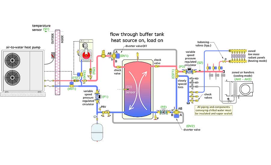
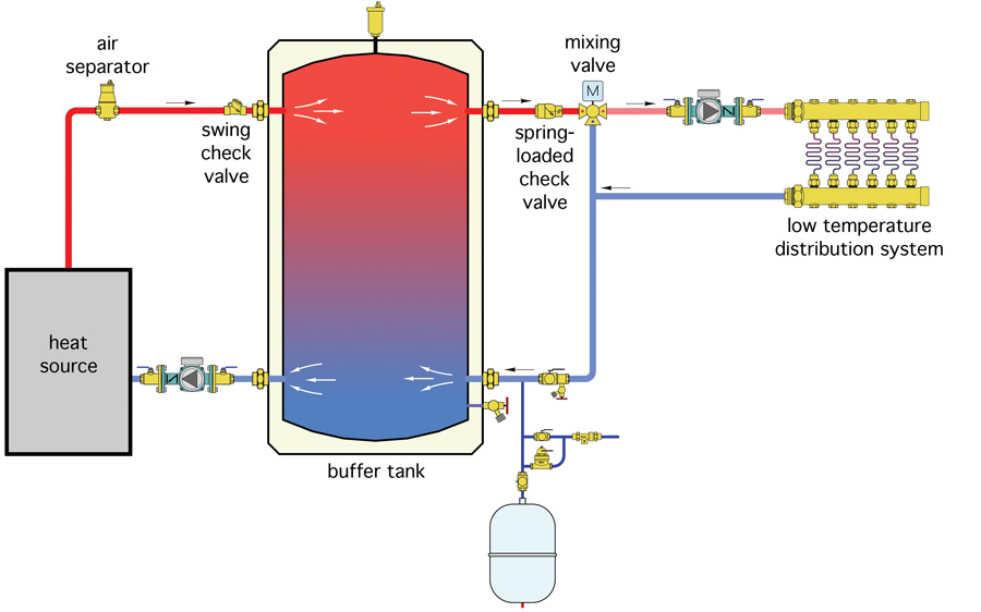
The buffer tank is used with a hydronic heating system. It sits between the load-side water coil of the water-to-water geothermal heat pump, and the hydronic heat distribution piping. Water circulates from the tank into the geothermal heat pump, where it is heated or cooled, and then back to the tank. Chilled water schematic and condenser water schematic, how to read and understand the engineering drawings with real world examples, Illustrations, animations and video tutorial. Covering chillers, pump sets, AHUs, risers, primary and secondary systems, cooling towers and bypass lines. Oct 22, 2014 · Either the traditional buffer tank piping shown in Figure 1 or the alternate method shown in Figure 5 can be used. Both have been used on many successful installations. It’s likely to come down to what tanks are available, how the piping connections on the tank are sized and located, and how those tanks would be optimally located in ... 2 questions:1) Anyone know of a diagram explaining how a Desuperheater should be plumbed with a 2 tank system (unpowered buffer & NG. Energy Star promotes the desuperheater; however, it only efficiently produces hot Open Loop Well - Typical piping diagram.
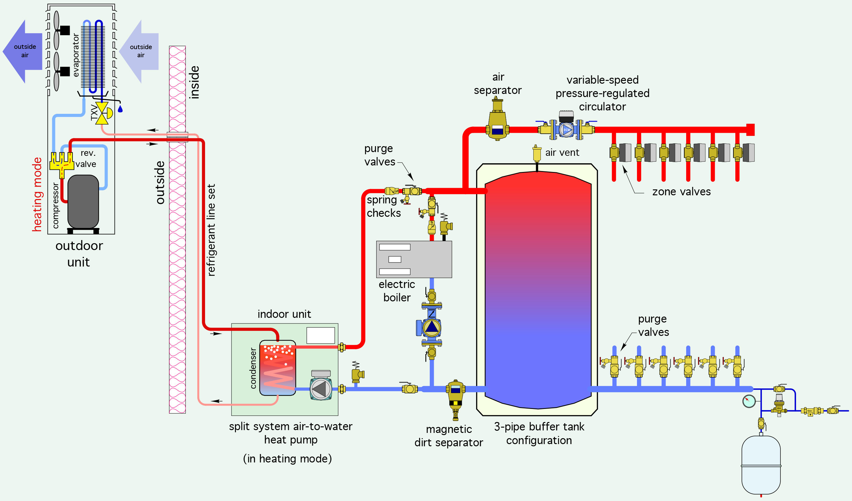
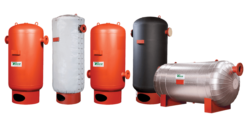
Buffer tanks are often employed within HVAC systems to provide additional system fluid volume in order to prevent short cycling of heating or cooling apparatus. Taco offers these tanks in sizes from 50 gallons up through 3000 gallons across 22 tank volumes. Each of these tank models is available with system connections on the side of the tank ... On-Demand Heater With Buffer Tank This diagram shows an instantaneous water heater system with a buffer tank and recirculation loop. The expansion tank is typically installed on the cold water inlet but can be installed on the hot water supply after the water heater. The use of the buffer tank is to assist when a large instantaneous demand occurs. piping buffer tank I would like to add a buffer tank to my system. Would it be OK to put the supply and return of the buffer tank in the boiler loop on the output side of the boiler? I was thinking of placing the buffer tank tees next to each other just beyond where the main boiler pipe comes out of the boiler. When to use a three-pipe buffer tank configuration November 5, 2018 By John Siegenthaler Hydronics. Sponsored. Pipe Freezing Solutions to Avoid System Shutdown. Armstrong Launches Single Phase Pumps for Light-Duty Installations ... and connecting the piping to the side of the tank rather than the top or bottom.
DESIGN DETAILS FOR AIR-TO-WATER HEAT PUMP | Caleffi Idronics
Piping Diagrams. Commercial Electric Heat Pump. Commercial Tank Type Electric. Commercial Tank Type Gas. Commercial Tankless. Domestic Circulating Water Heaters.
Hydronic Heating Buffer Tanks Part 2 - Sizing | R.L. Deppmann
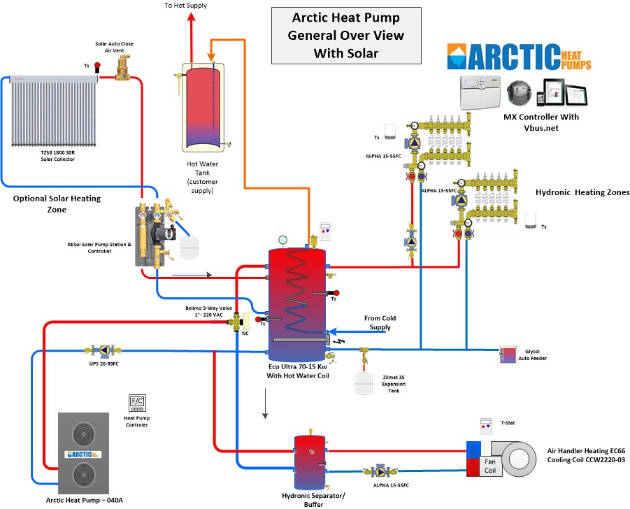
All system components from Solarbayer, including a wood gasifying boiler, stratification buffer tanks, solar DHW tank and a thermal solar system with flat plate collectors. Heating diagrams A collection of hydraulic drawings of established installation
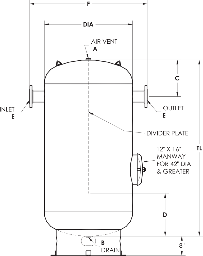
ASME-Chilled-Water-Buffer-Tanks-Dimension-Diagram - Elbi of ...
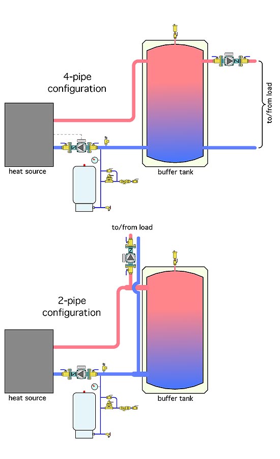
If the buffer tanks have the four principal piping connections shown in Figures 1 through 3, it is possible join two or three of them together in a “close coupled” arrangement as shown in Figure 6. FIGURE 6 This piping allows the two buffer tanks to maintain flow dynamics very similar to the single “2-pipe” buffer tank shown in figures 4 and 5.
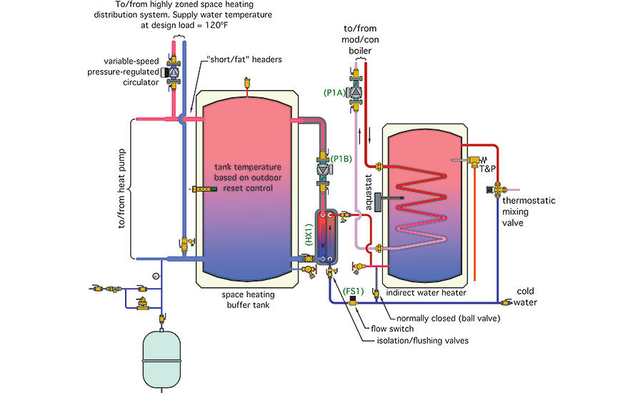
Hydronics Zone: Combining a Water-to-water Heat Pump with a ...
Pipe size of hydraulic separato r 1" 1.25" 1.5" 2" 2.5" 3" 4" 6" Max flow rate (GPM) 11 18 26 40 80 124 247 485 The header piping connecting to the distribution side of the Hydro Separator should be sized for a flow of 4 feet per second or less under maximum flow rate conditions.
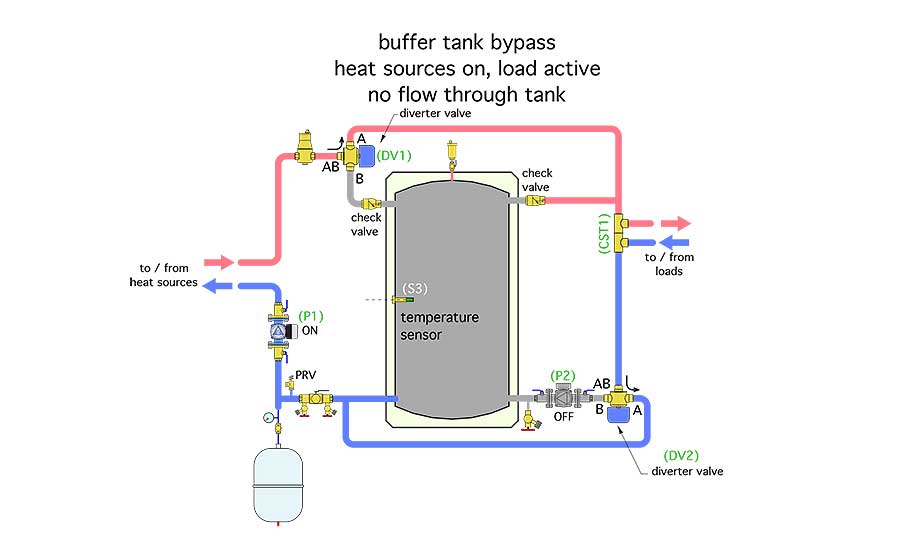
Details for bypassing thermal storage | 2017-10-24 | PM Engineer
Taco Chilled & Hot Water Buffer Tanks are designed, constructed and tested to ASME Section VIII, Div. 1 requirements. Computerized product selection helps you choose the Buffer Tank that is just the right fit for your application requirements. All fabrication is done in-house to assure a high level of quality. eLink ® is Taco Comfort Solutions ...
10. Piping schematic of the buffer tanks (Crofoot, 2012 ...
13. Wire the tank or system/pipe sensor connected to the DHW sensor terminals on the follower boiler addressed as #1. 14. The system/pipe sensor must be placed on common piping to the tank, as close to the tank as possible. 15. The system/pipe sensor is wired to the system sensor terminals on the master boiler.
.jpg)
Chilled Water HVAC
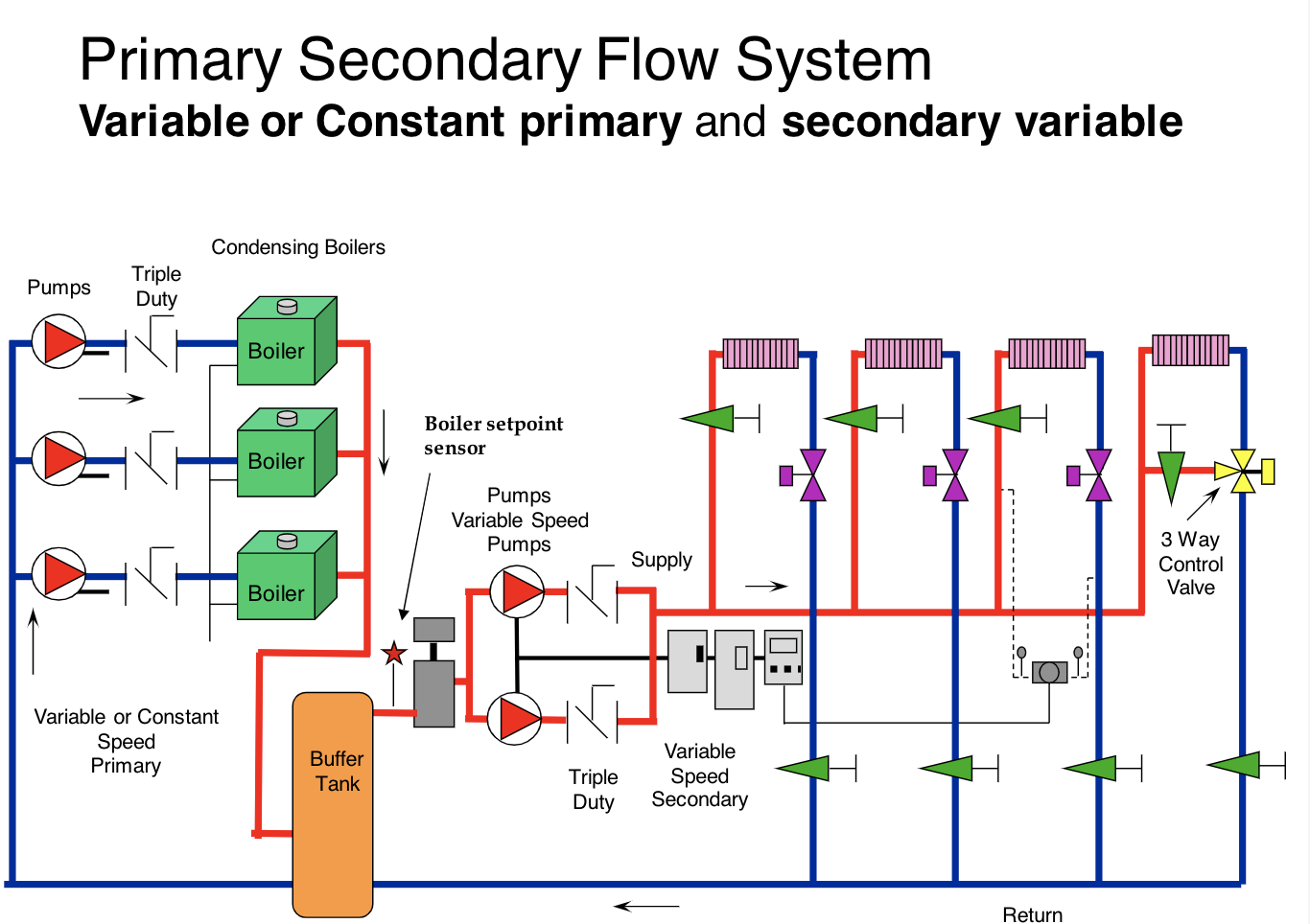
As the primary loop volume is very small, we have added buffer tanks on the return piping (before the pumps) to prevent chillers from short cycling. Due to some local availability constraints, we have to use 4 buffer tanks (1000 gal. each) piped in series instead of a large one.

Impovements to ERGOMAX & Buffer Tanks
See example piping diagram between a storage tank and an indirect gas fired water heater (FIG's 2-2 and 2-3). NOTICE See the Water Heater's Installation and Operation manual for specific piping diagrams that match the inlet / outlet water tappings on the tank to the inlet / outlet water tappings on the water heater.
John Siegenthaler: Due diligence | 2020-09-22 | Plumbing ...
22 Aug 2018 — Looking for a piping digram for the use of a buffer tank. We've installed many boilers with indirects, but never had to use a buffer tank ...

Buffer Tank / Hydraulic Separator | Lochinvar
Amtrol ASME Buffer Tanks add capacity to non-potable, closed systems to help reduce cycling, improve temperature control and provide more consistent system operation. Available for chilled water and hot water applications. All Amtrol Buffer Tanks are made in the USA at our ISO 9001:2015 registered facilities. FEATURES.
Storage Tanks - Energy Buffer Tanks
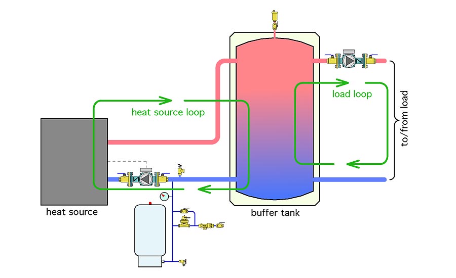
The advantage of 2-pipe tanks. A 2-pipe buffer tank places the piping leading to and from the heating load between the heat source and the buffer tank. If the load is operating at the same time as the heat source, which is common, the flow rate passing into the buffer tank is the difference between the heat source flow rate, and the load flow rate.
John Siegenthaler: Due diligence | 2020-09-22 | Plumbing ...
Condensing Boiler Piping Design - Hot Water Buffer Tanks. Condensing Boiler Piping Design - Hot Water Buffer Tanks.
.jpg)
Chilled Water HVAC
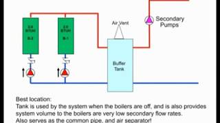
Increasing pipe size reduces velocity and creates area of very low pressure drop Hydraulic Separator with air/dirt media Hydraulic Separator “BUFFER” TANKS Purpose: increase the amount of fluid in a system to prevent the short cycling of chillers, boilers, etc. Buffer Tank Two connections – Volume Multi-Purpose Tank Four connections –
Hydronic Buffer Tanks INSTALLATION, OPERATION & MAINTENANCE ...
is available for alternate piping configurations. When configured and piped correctly, Heat-flo hydronic buffer tanks can serve as both a thermal buffer and a hydraulic separator - allowing the heating or cooling source to be hydraulically decoupled from the distribution system. HYDRONIC BUFFER TANKS
John Siegenthaler: Due diligence | 2020-09-22 | Plumbing ...
A: Buffer tanks provide extra water volume in a closed chilled water system. Q:Are buffer tanks used in every chilled water system? A: No. Some systems have an adequate volume of water in them so the extra storage provided by the buffer tank is not required. Q: How do they work? A: The added capacity, provided by the tank, reduces
Buffer Tanks for Cold and Hot Water Systems | Wessels Company
Product Drawings. Piping Diagram. Technical Papers. 3D-Drawings. Spec Sheets. CEMLINE® has made a series of typical piping arrangements for the Model Series: SEH, SSH, SWH, and USG. These drawings are in .DWG format or Adobe®Acrobat® (PDF) format. The Acrobat Reader is available free from Adobe. Note: Select the model and click on the ...

LoLiMoT based MPC for air handling units in HVAC systems ...
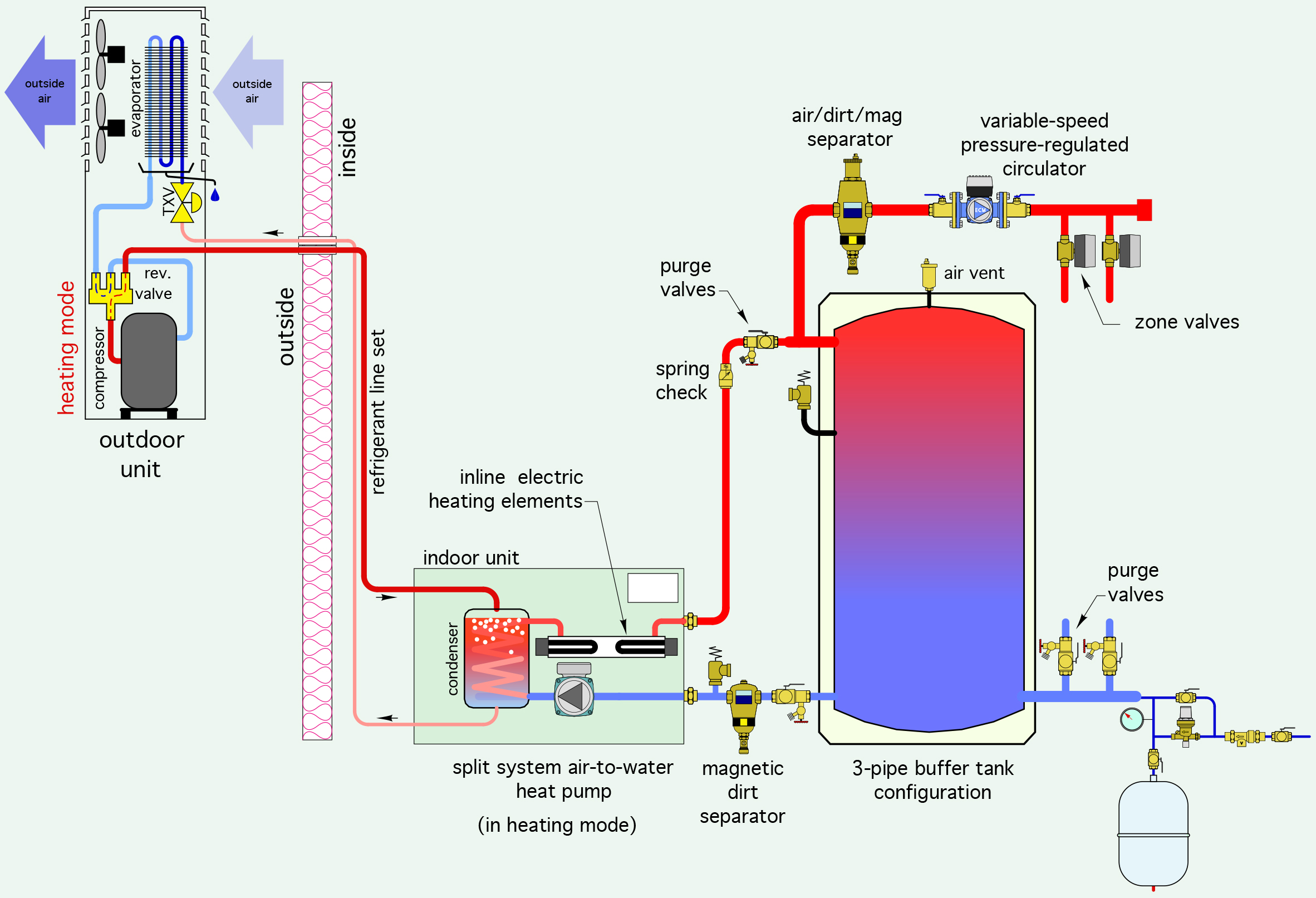
DESIGN DETAILS FOR AIR-TO-WATER HEAT PUMP | Caleffi Idronics
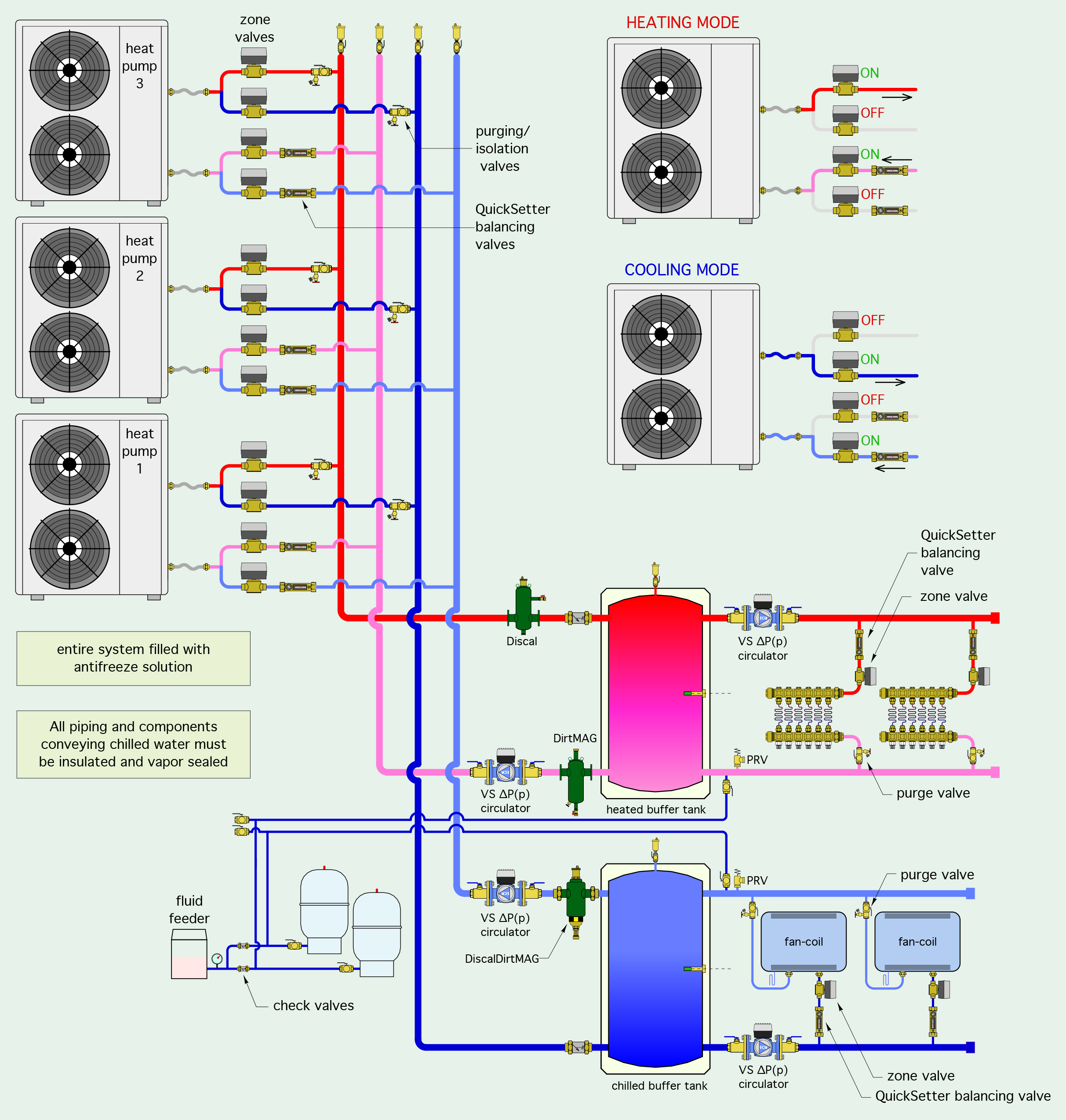
5: CONTEMPORARY SOURCES FOR CHILLED WATER | Caleffi Idronics
A Buffer tank issue? | Terry Love Plumbing Advice & Remodel ...

Dual-fuel Combisystem: The Benefits of Geothermal | 2016-05 ...

View simple piping and wiring drawings for residential ...
Details for bypassing thermal storage | 2017-10-24 | PM Engineer

Buffer tanks | Terry Love Plumbing Advice & Remodel DIY ...
Buffer Tank Piping Modifications: Dual to Single Direction ...
Chilled Water Buffer Tanks

Impovements to ERGOMAX & Buffer Tanks
Condensing Boiler Piping Design - Hot Water Buffer Tanks ...

Boiler Buddy 50 gallon Steel Buffer Tank | Winsupply

buffer tank piping — Heating Help: The Wall

10. Piping schematic of the buffer tanks (Crofoot, 2012 ...
One side or the other - HPAC Magazine
Peerless PureFire

HeatSpring Magazine – 2-Pipe Versus 4-Pipe Buffer Tank ...
Peerless PureFire

HeatSpring Magazine – 2-Pipe Versus 4-Pipe Buffer Tank ...

View simple piping and wiring drawings for residential ...
Hydronic Condensing Boiler Heating Buffer Tanks - Part 1 of 3 ...
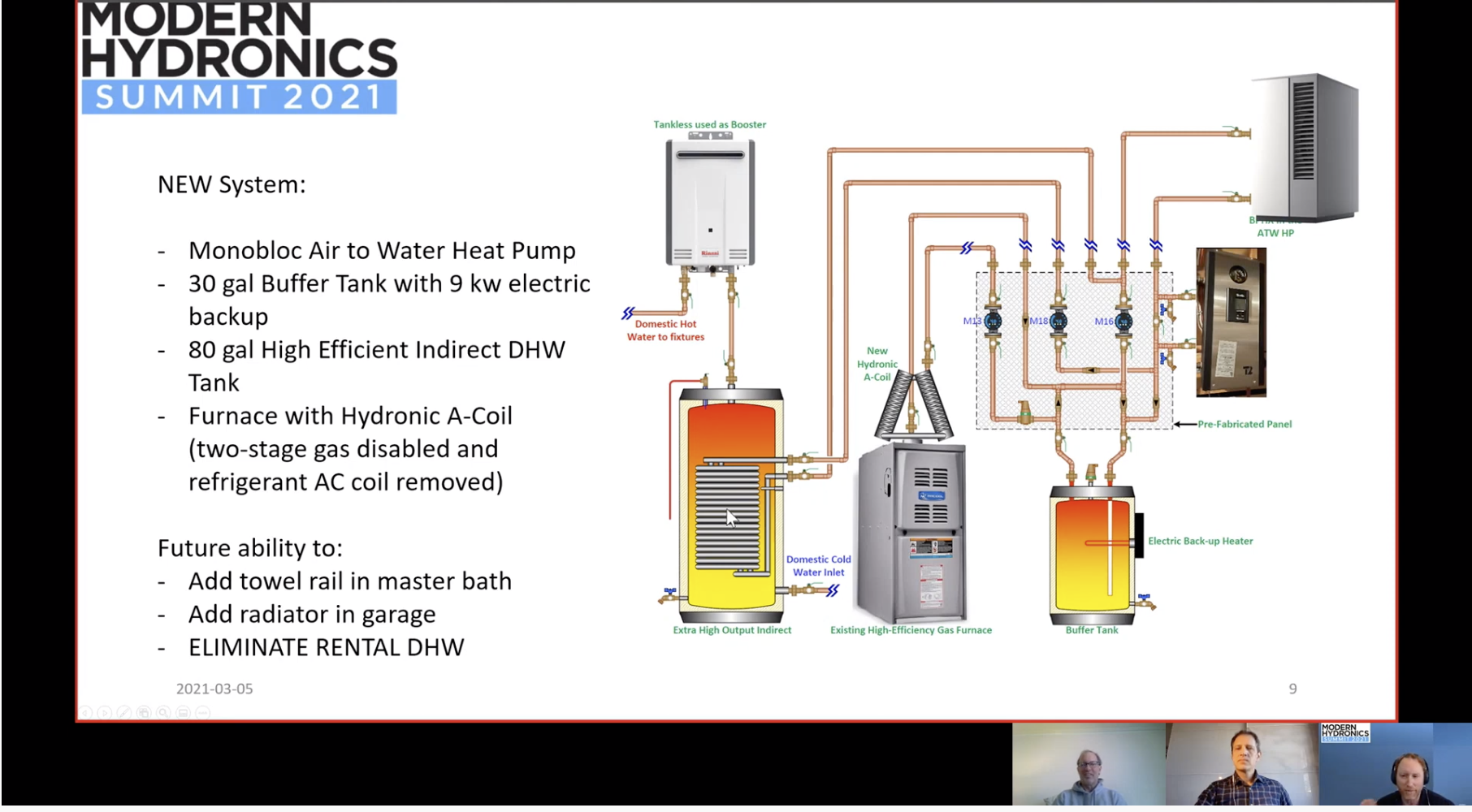
Air-to-Water Heat Pump Experience - HPAC Magazine
Chilled & Hot Water Buffer Tanks | www.tacocomfort.com

Buffer tanks: Raypak | 2011-10-31 | Engineered Systems Magazine
0 Response to "41 buffer tank piping diagram"
Post a Comment