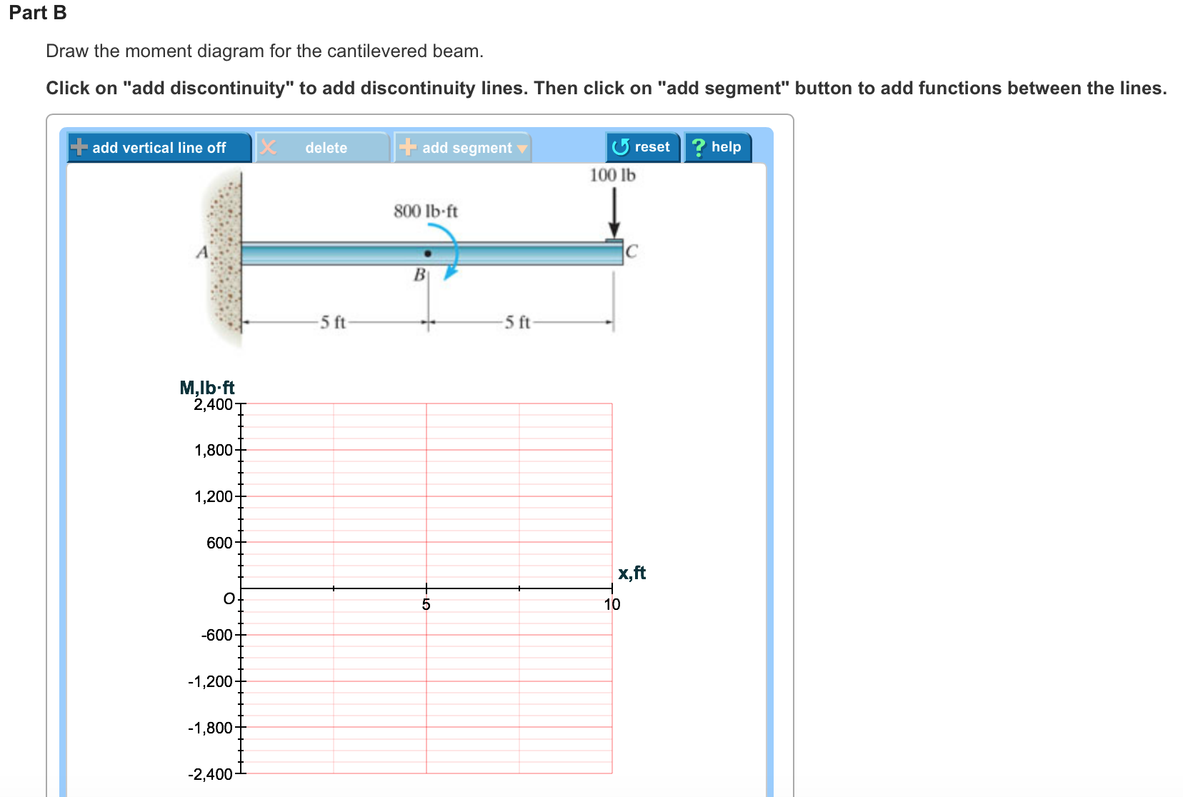
39 draw the moment diagram for the cantilevered beam.
Free Online Beam Calculator for Cantilever or ... - SkyCiv Any changes made will automatically re-draw the free body diagram any simply supported or cantilever beam. The beam reaction calculator and Bending Moment Calculations will be run once the "Solve" button is hit and will automatically generate the Shear and Bending Moment Diagrams. Draw the shear-force and bending-moment diagrams for a ... Answer of Draw the shear-force and bending-moment diagrams for a cantilever beam with two concentrated loads (Fig. 4-19a).
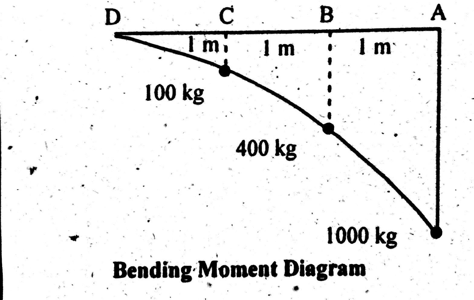
Bending moment and shear force diagram of a cantilever beam A bending moment diagram is the graphical representation of the variation of he bending moment along the length of the beam and is abbreviated as B.M.D. We will take different cases of beams and loading for plotting S.F. D and B.M.D. Cantilever : Point Load at the End (Fig. 3.8)

Draw the moment diagram for the cantilevered beam.
Shear Force & Bending Moment Diagram of Cantilever Beam ... Shear Force & Bending Moment Diagram of Cantilever Beam Structural Mechanics Civil Engineering HindiShear Force Diagram SFD & BMD Bending Moement Diagram of ... Mechanical Design of a Shaft - S.B.A. Invent The first step to solving the problem is to draw a free body diagram. First let’s look at the 500 lb weight. Assuming that the object that is supporting the shaft is infinitely stiff, the above problem can be treated as a cantilever beam. From that a free body diagram can be drawn, and the shear and moment diagrams can be determined. Beam Reactions and Diagrams - Strength of Materials ... Now, flip the beam horizontally 180º (or change the observation point, looking at the beam from the opposite side) and draw the diagrams, starting from the same point A. The diagrams will appear as follows: Note that, while the shear force diagrams appeared to be mirrored images (flipped horizontally), the bending moment diagram is not affected.
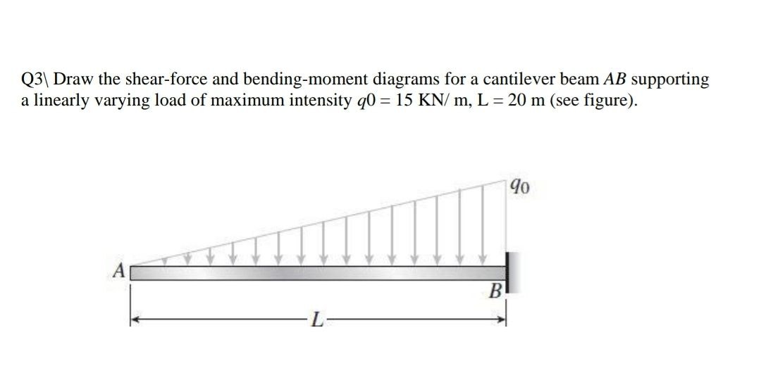
Draw the moment diagram for the cantilevered beam.. Solution to Problem 410 | Shear and Moment Diagrams ... Problem 410 Cantilever beam carrying the uniformly varying load shown in Fig. P-410. [collapse collapsed title="Click here to read or hide the general instruction"]Write shear and moment equations for the beams in the following problems. In each problem, let x be the distance measured from left end of the beam. Also, draw shear and moment diagrams, specifying values at all (PDF) Shigley's. 2015. Mechanical Engineering Design. 10th ... Libro de diseño de máquinas de Shigley Formula For Maximum Bending Moment In Simply Supported Beam Cantilever Beam Udl And End Bending Moment. ... How To Draw Shear Force Bending Moment Diagram Simply Supported Beam Exles Ering Intro. Sf And Bm 0032 Png. Beam Deflection Calculator. Beam Design. Solved A Simply Supported Beam Deflects By 5 Mm When It Is Subjecte. Draw The Shear Diagram For Cantilever Beam - The Best ... Draw Your Shear Force And Bending Moment Diagrams Required For Civil Engg By In132 Fiverr. Shear Force Bending Moment Diagram Of Cantilever Beam Exles Ering Intro. A Cantilever Beam Is Subjected To Various Lo As Shown In Figure Draw The Shear Force Diagram And Bending Moment For Ethiotutors. Solved Draw The Shear Force Diagram And Ben.
Shear Force & Bending Moment Diagram of Cantilever Beam ... Shear force on cantilever beam is the sum of vertical forces acting on a particular section of a beam. While bending moment is the algebraic sum of moments about the centroidal axis of any selected section of all the loads acting up to the section. Example: Draw shear force and bending moment diagrams of the cantilever beam carrying point loads. Draw the shear force and bending moment diagram for the ... Draw the shear force and bending moment diagram for the beam shown. Neglect the weight of the beam. ... Draw the shear force and bending moment diagram for the beam shown. Neglect the weight of the beam. Transcribed Image Text: 500 lb/ft 8000 lb ft 8000 lb ft B 10 ft Expert Solution. Want to see the full answer? Check out a sample Q&A here. Draw The Moment Diagram For Cantilever Beam - The Best ... Draw The Shear And Moment Diagrams For Cantilever Beam In Fig 6 15 A Holooly. Solved Draw The Shear And Moment Diagrams For Cantilever Beam 1 Transtutors. Express The Internal Shear And Moment In Cantilevered Beam As A Function Of X Then Draw Diagrams Holooly. Solved Develop Mathematical Expression And Draw The Shear Force 1 Transtutors. SOLVED:Draw the shear and moment diagrams for the loarled ... So first we have to find the internal force at the support and uh find a moment at the support. So first, from this family diagram we will have that A. Y. Is equal to two K. Newton, from sigma F. Y. Equal to zero and from sigma equals zero, we'll have that M. A. 89 You don't even meet her. And so that we can draw the sheer force we in kilo newton.
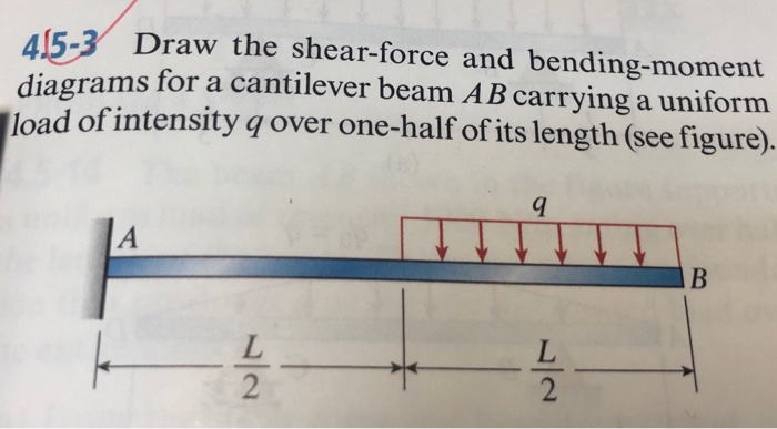
How to draw shear force diagram and bending moment diagram ... This video explains how to draw shear force diagram and bending moment diagram (S.F.D. & B.M.D.) in case of cantilever beam carrying uniformly distributed lo... Solved Draw the shear and moment diagrams for the - Chegg Step-by-step answer. Who are the experts? Experts are tested by Chegg as specialists in their subject area. We review their content and use your feedback to keep the quality high. Transcribed image text: Draw the shear and moment diagrams for the cantilevered beam. Solved 7-48 Draw the shear and moment diagrams for the ... Advanced Physics. Advanced Physics questions and answers. 7-48 Draw the shear and moment diagrams for the cantilevered beam. 100 Ib s ft HW HAND IN IN BB. Mechanics of Materials by Andrew Paytel - Academia.edu Enter the email address you signed up with and we'll email you a reset link.
PDF HW 10 SOLUTIONS - University of Utah *7—56. Draw the shear and moment diagrams for the cantilevered beam. 300 1b - diagram of the beam's left through an arbitrary shown in fig. b will be to write the and mcnnent quations. The inœnsity the triangldar útributed load at of sectioning is — = 3333r Referring Fig. b , o V = {-300- 1b — +3001-0
How to draw shear force diagram & bending moment diagram ... Click here for more videos on SFD & BMD: video explains how to draw shear force diag...
Answered: Draw the shear and moment diagrams for… | bartleby Draw the shear and moment diagrams for the cantilever beam shown and determine the maximum absolute value of the shear and bending moment. Indicate the degree of each curve. You may use the method of sections, area method, or both. 15 kN/m 8 kN 5 kN/m В C D 20 kN m 8 kN/m - 2 m 3 m 6 m.
Strength of materials by s k mondal pdf - Issuu 14.1.2017 · S K Mondal’s. Strength of Materials Contents Chapter – 1: Stress and Strain Chapter - 2 : Principal Stress and Strain Chapter - 3 : Moment of Inertia and Centroid Chapter - …
Draw The Moment Diagram For Cantilevered Beam - The Best ... Draw The Moment Diagram For Cantilevered Beam Study. ... Draw the shear and moment diagrams for cantilever beam in fig 6 15a 2 kn 1 5 homeworklib 329 6 1 draw the shear and moment diagrams for aeros shear force bending moment diagram of cantilever beam exles ering intro shear force and bending moment diagrams sfd bmd shear force and bending ...
Draw the shear and moment diagrams for the cantilevered beam 3. Take different beam sections and draw the free-body diagram of one of the segments. The shear force V and bending moment M should be shown acting in their positive sense, in accordance with the sign convention. 4. Calculate the shear force by summing forces perpendicular to the beam's axis. 5.
Draw Bending Moment & Shear Force Diagrams - Cantilever Beam This video explains how to draw shear force diagram and bending moment diagram with easy steps for a cantilever beam loaded with a concentrated load. Shear f...
Answered: Draw the shear and Moment diagrams for… | bartleby Draw the shear and Moment diagrams for a cantilever beam AB of span L = 10 m supporting a uniformly distributed load w = 100 kN/m as shown in the figure. w A В -L- Question Transcribed Image Text: Draw the shear and Moment diagrams for a cantilever beam AB of span L 10 m supporting a uniformly distributed load w = 100 kN/m as shown in the figure.
Draw A Free -Body Diagram Of The Cantilever Beam And ... A cantilever beam is subjected to loads shown below. a) Draw the free-body diagram of the beam. b) Draw the internal shear and bending moment diagrams for the entire beam using the relations among load, shear force and bending moment (i.e. the...
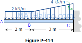
Shear Force and Bending Moment Diagram for Cantilever Beam ... Shear Force and Bending Moment Diagram of Cantilever beam when point load is applied From the figure we have the value of load at point A and point B. So let's draws the shear force diagram with the help of these loading. Bending moment at point A is zero. Bending moment at point B= -2*2 = 4 KN-M Bending moment at point C= -2*4-4*2 = 12 KN-M
Answered: Draw the shear and Moment diagrams for… | bartleby Draw the shear and Moment diagrams for a cantilever beam AB of span L = 10 m supporting a uniformly distributed load w = 100 kN/m as shown in the figure. %3D w A В -L- Question Transcribed Image Text: Draw the shear and Moment diagrams for a cantilever beam AB of span L 10 m supporting a uniformly distributed load w = 100 kN/m as shown in the ...
PDF 4. Bending Moment and Shear Force Diagram Chapter-4 Bending Moment and Shear Force Diagram S K Mondal's Maximum bending moment, 2 max wL 2 M at fixed end Another way to describe a cantilever beam with uniformly distributed load (UDL) over it's whole length. (iii) A Cantilever beam loaded as shown below draw its S.F and B.M diagram In the region 0 < x < a
Draw the shear and moment diagrams for the cantilever beam ... Draw the shear and moment diagrams for the cantilever beam.
Draw the shear and moment diagrams for the overhang beam ... Shear Diagram. The shear of −2 kN at end A of the beam is plotted at x = 0, Fig. 6-16 c . The slopes are determined from the loading and from this the shear diagram is constructed, as indicated in the figure. In particular, notice the positive jump of 10 kN at x = 4 m due to the force B_y, as indicated in the figure. Moment Diagram.
Draw the moment diagrams for the beam using the method of ... Draw the moment diagrams for the beam using the method of superposition. Consider the beam to be cantilevered from the rocker at B. Results. See All Results. Question: Structural Analysis [EXP-546] Draw the moment diagrams for the beam using the method of superposition. Consider the beam to be cantilevered from the rocker at B.
Mechanical Design - an overview | ScienceDirect Topics Mechanical design is to design parts, components, products, or systems of mechanical nature. For example, designs of various machine elements such as shafts, bearings, clutches, gears, and fasteners fall into the scope of mechanical design. Numerous criteria have been proposed in mechanical design processes, some primary design criteria include functions, safety, …
Beam Reactions and Diagrams - Strength of Materials ... Now, flip the beam horizontally 180º (or change the observation point, looking at the beam from the opposite side) and draw the diagrams, starting from the same point A. The diagrams will appear as follows: Note that, while the shear force diagrams appeared to be mirrored images (flipped horizontally), the bending moment diagram is not affected.
Mechanical Design of a Shaft - S.B.A. Invent The first step to solving the problem is to draw a free body diagram. First let’s look at the 500 lb weight. Assuming that the object that is supporting the shaft is infinitely stiff, the above problem can be treated as a cantilever beam. From that a free body diagram can be drawn, and the shear and moment diagrams can be determined.
Shear Force & Bending Moment Diagram of Cantilever Beam ... Shear Force & Bending Moment Diagram of Cantilever Beam Structural Mechanics Civil Engineering HindiShear Force Diagram SFD & BMD Bending Moement Diagram of ...













0 Response to "39 draw the moment diagram for the cantilevered beam."
Post a Comment