42 free body diagram torque
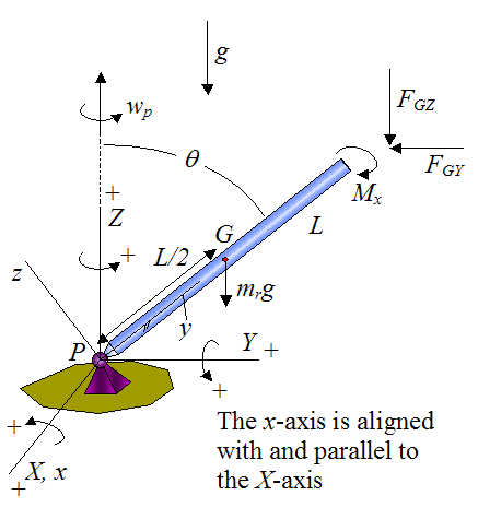
PDF Recitation 4 Notes: Torque and Angular Momentum, Pendulum ... Torque and Angular Momentum of a Particle The figure below shows a fixed coordinate system OXY Z containing a mass m moving with velocity v, having momentum p , and being acted upon by a resultant force, f . X Y Z O ... The free body diagram depicting the torques on the body is shown below. Note the directions of the unit RE: Shaft Mounted Gearbox Free Body Diagram - Mechanical ... But as a piece of advice, when you put a free body diagram up for comments, as Rb stated, you must show it in equilibrium and the out of plane forces and moments must be shown in the diagram Anyway, in summary your free body on the shaft should read. 200nM ccw, 200nm cw ,wihth an asterisk 96*9,8n upwards and 98,6 downwards with an asterisk.
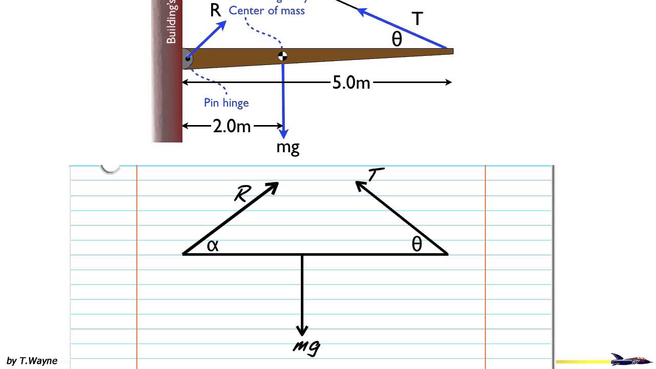
PDF Torque Torque and Rotational Inertia - Boston University Torque and Rotational Inertia 2 Torque Torque is the rotational equivalence of force. So, a net torque will cause an object to rotate with an angular ... Draw a free-body diagram for a horizontal rod that is hinged at one end. The rod is held horizontal by an upward force
Free body diagram torque
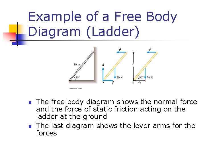
Mechanics Map - Axial Force Diagrams and Torque Diagrams To create the torque diagram for a shaft, we will use the following process. Solve for all external moments acting on the shaft. Draw out a free body diagram of the shaft horizontally, rotating the shaft if necessary, so that all torques act around the horizontal axis. Lined up below the free body diagram, draw a set of axes. 1.5-3: Free body Diagrams with torque - YouTube Basic static equilibrium examples that emphasize drawing the free body diagram, choosing an axis, and evaluating torque without bothering to work out the num... Torque; and objects in equilibrium - Boston University This is something of a tricky problem, because you have to draw the free-body diagram of the entire ladder to figure out the normal forces, and then draw the free-body diagram of one half of the ladder to complete the solution. This is also what makes it a good example to look at, however. Consider first the free-body diagram of the entire ladder.
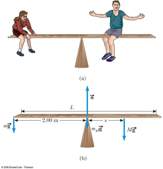
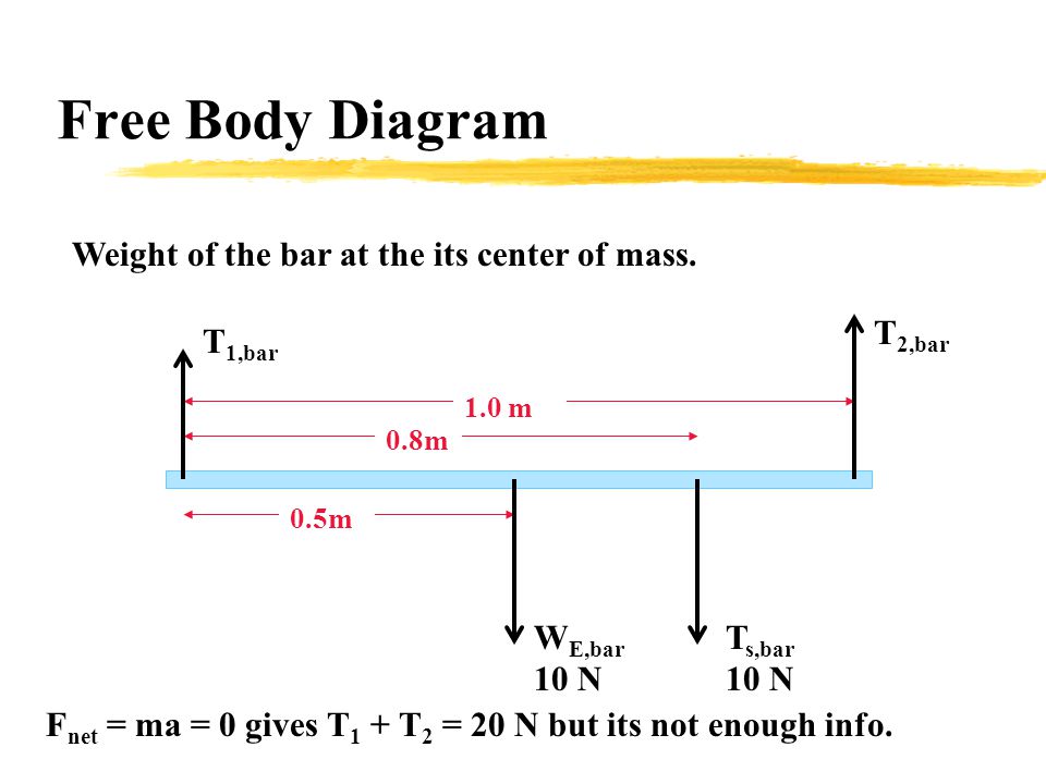
Free body diagram torque. Extended Free Body Diagrams - mrwaynesclass.com Identify the reaction force on your free body diagrams and extended free body diagrams two forces. The weight of the beam is located at the center of mass of the beam. If you were to hold the beam up with one finger, you would lift at the center of mass with a force equal to the weight of the beam. How to Draw a Torque Diagram Without Equations - YouTube In this video, we solve a torque diagram without having to use equations. By simply looking at the external loadings, we can easily draw the internal torque... Free-body diagrams and torque - Physics Forums Free-body diagrams and torque Thread starter Niles; Start date Dec 23, 2007; Dec 23, 2007 #1 Niles. 1,868 0. Homework Statement Two friends are carrying a crate of mass 200 kg up a flight of stairs. The crate has length 1.25 m and height 0.50 m, and its center of gravity is at its center. The stairs make a 45.0 angle with respect to the floor. Mathematical Models of Translating Mechanical Systems Free body diagram at θ 1: Free body diagram at θ 2: There are 4 torques acting: The external torque, τ a, clockwise. The torque due to K r.. If θ 1 increases (counterclockwise), K r causes a clockwise torque on J 1.; The resulting torque is K r ·θ 1, clockwise.; The torque due to B r1.. If θ 1 increases, the resulting torque on J 1 is B r1 ·ω 1 in the clockwise direction.
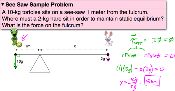
Solved A) Draw a free-body diagram. Show the torque ... Draw a free-body diagram. Show the torque reactions at supports A and C in the correct direction for resisting the applied torque, T. From your free-body diagram, write the equilibrium equation for the torques. Express the torsional equation of equilibrium for the shaft in terms of TA, and TC. B) Basic Biomechanics: Moment Arm & Torque Torque = Force (Fm) x Moment Arm Free-Body Force Diagrams allow for identification of all the components of a force system (including torque) Torque in Biomechanics Torque is what creates biomechanical movement. It is what creates the movement of the lever system (bones). This is important to understand. Force Calculations The Free Body Diagram looks like this: The upwards force R balances the downwards Weight. With only those two forces the beam will spin like a propeller! But there is also a "turning effect" M called Moment (or Torque) that balances it out: Moment: Force times the Distance at right angles. Layout and free body diagram of a single planetary gear ... The layout of a single plane- tary gear set and its free body diagram is shown Figure 1, where N, r, T, and w represent the teeth num- ber, radius, torque, and angular velocity of gear ...
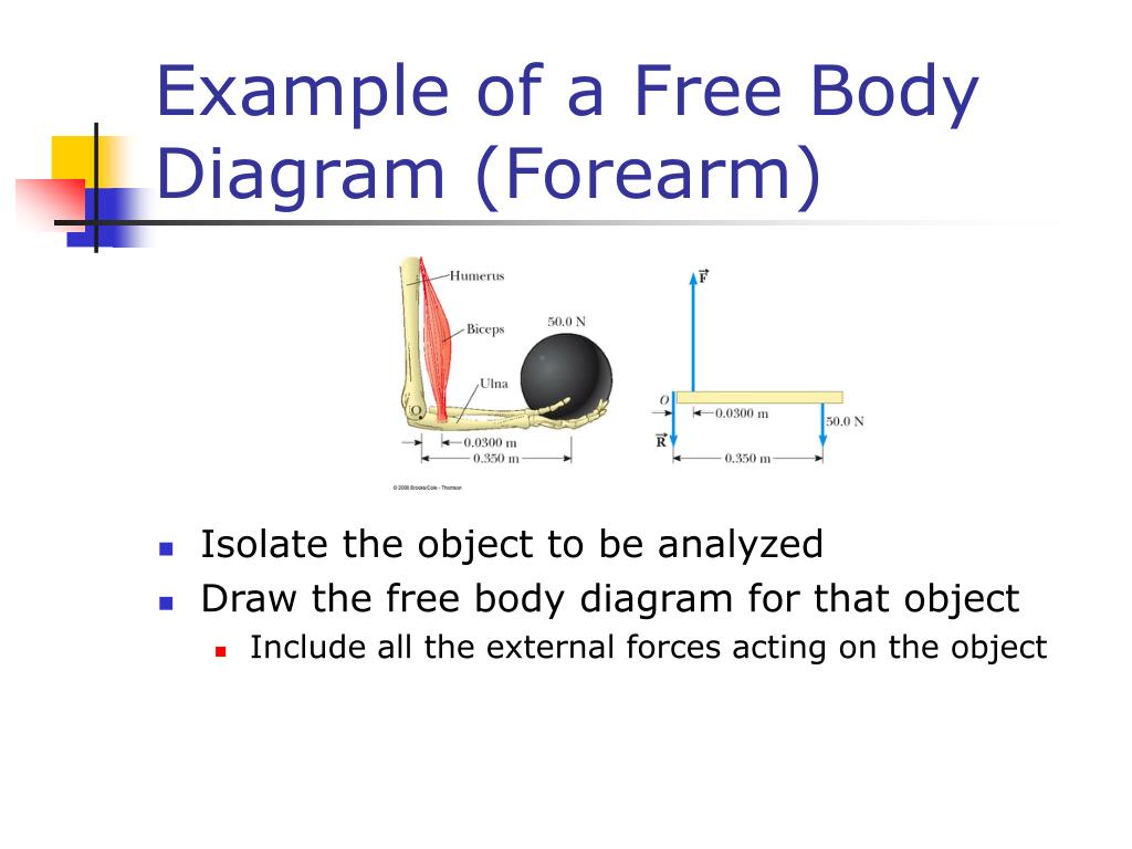
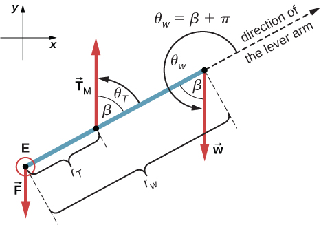
Free Body Diagrams | Hot Rod Forum The basis for a free body diagram is the principle that a body's dynamic status can only be affected by its contact with the outside world. The arrows replace and represent the effects of the outside world. In this case, we've considered the entire car as "the body." It's only contact with the outside world is through its tire patches. Free Body Diagram - an overview | ScienceDirect Topics In Fig. 4.4b, the free body consists of the three moving links isolated from the frame 0.The forces acting on the system include a driving torque M,an external driven force F,and the forces transmitted from the frame at kinematic pair A, F 01,and at kinematic pair C, F 03. Figure 4.4c is a free-body diagram of the two links 1 and 2. Figure 4.4d is a free-body diagram of a single link. PDF Free Body Diagrams - World Class CAD Free Body Diagrams In this chapter, you will learn the following to World Class standards: 1. Measuring Force Results from Gravity Acting on a Mass 2. Solving a Mechanics Problem with a Free Body Diagram 3. Making Minor Changes in Mechanics to Reinforce Learning 4. Drawing a Free Body Diagram with Torque Equaling Zero 12.2 Examples of Static Equilibrium - University Physics ... Next, we read from the free-body diagram that the net torque along the axis of rotation is + rTTy − rwwy = 0. 12.23 Equation 12.23 is the second equilibrium condition (for torques) for the forearm. The free-body diagram shows that the lever arms are rT = 1.5in. and rw = 13.0in.
Extended Free Body Diagram Tutorial
Free Body Diagrams | Representations | Videos | STEM ... A free body diagram is not likely to shed much light on the problem. This problem involves rotation and torque. Free body diagrams work best with linear motion. Even though force is involved, a free body diagram may not help. However, a more sophisticated diagram may be of assistance.
Static equilibrium
Equilibrium and Free-body Diagrams and Torques in ... Free-body diagrams, or force diagrams, are often drawn in order to understand the forces and torques acting on systems in equilibrium. Each contributing force or torque is represented by an arrow whose size and direction fully describes the vector in question. Through vector addition, the translational system is shown to be in equilibrium.

Solved C. Torque and angular acceleration. 1. Draw an | Chegg.com
Drawing Free-Body Diagrams - Physics Classroom Drawing Free-Body Diagrams. Free-body diagrams are diagrams used to show the relative magnitude and direction of all forces acting upon an object in a given situation. A free-body diagram is a special example of the vector diagrams that were discussed in an earlier unit. These diagrams will be used throughout our study of physics.
torque
Solved Questions - Torque and Equilibrium Extended free ... Transcribed image text: Questions - Torque and Equilibrium Extended free-body diagrams are handy when determining the torques on a system. An extended freo-body diagram not only shows the forces acting on an object but Indicates a location on the object at which the force can be regarded as acting. Process for drawing extended free-body diagrams 1.
Torque and Equilibrium
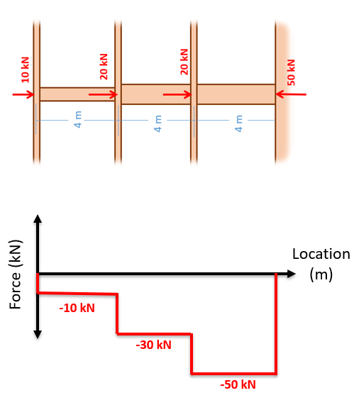
PDF Internal Loads Normal Force and Torque Diagrams Draw a free-body diagram of the shaft on either side of the cut Use a static-equilibrium equation and the following sign convention to obtain the internal torque at the section Sign Convention Using the right-hand rule, the torque and angle of twist will be positive, provided the thumb is directed outward from the shaft when the
![183_notes:torquediagram [Projects & Practices in Physics]](https://msuperl.org/wikis/pcubed/lib/exe/fetch.php?w=400&tok=19bb88&media=183_notes:week12_torquediagrams2.png)
183_notes:torquediagram [Projects & Practices in Physics]
PDF Free Body Diagrams with Animated GIF Files Free body diagram (FBD), machine design, statics, and animated GIF. Free Body Diagrams of Mechanical Systems . A free body diagram (FBD) is a graphic representation of a body (element or segment of an element, subassembly, or assembly) in which - all connecting bodies have been removed, or the body is "freed" from connecting bodies, to shows
Phys - Lecture on torque
What is the free body diagram of force acting on a leaf ... Answer: Here's a free body diagram of a leaf spring used in the back of a car: And here's a general FBD of a leaf spring: Sources - 2 polish books: * 1 image: "Samochód. Teoria, konstrukcja i obliczanie" (Automobile. Theory, design and calculations) K. Studziński * 2 image: "Przykłady oblicz...

What force is causing the torque in this diagram? : r/AskPhysics
Chapter 12 Torque Construct extended force diagrams that account for rotation of objects. Slide 12-35. Page 36. Procedure: Extended free-body diagram.152 pages

Lead Screw with Friction - MATLAB & Simulink
PDF Mechanics lecture 7 Moment of a force, torque, equilibrium ... Free body diagrams • A free body diagram shows a body isolated from other bodies • All external forces and torques acting on it are shown To solve for a body in equilibrium: 1. Decide on the body of interest 2. Draw a diagram of the body isolated from other bodies in contact with it 3.
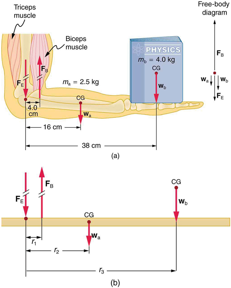
Forces and Torques in Muscles and Joints | Physics
Drive Shafts - Roy Mech Produce a free-body sketch of the shaft. Replacing the various associated components with their equivalent load/torque components; Produce a bending moment diagram for the xy plane and the xz plane (x = shaft axis direction). Note: The resulting internal moment at any point along the shaft = M x = Sqrt (M xy 2 + M xz 2) Produce a torque diagram.

A free-body diagram that is typical of what is found in ...
Free body diagram (FBD) showing various torque components ... Download scientific diagram | Free body diagram (FBD) showing various torque components acting on the shaft. from publication: Active control of the tip vortex: An experimental investigation on ...

Torque and Equilibrium Questions
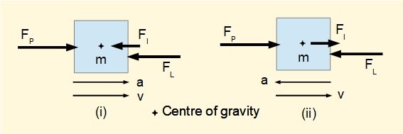
FREE BODY DIAGRAMS. Introduction: A free body diagram is a picture of the forces which act on an object and is the first (and perhaps the most important) step in solving force problems. Purpose: The purpose of the free body diagram (FBD) is to help you identify and analyze the forces that act on a particular object or body.
PPT - Rotational Motion and Torque PowerPoint Presentation ...
Torque; and objects in equilibrium - Boston University This is something of a tricky problem, because you have to draw the free-body diagram of the entire ladder to figure out the normal forces, and then draw the free-body diagram of one half of the ladder to complete the solution. This is also what makes it a good example to look at, however. Consider first the free-body diagram of the entire ladder.
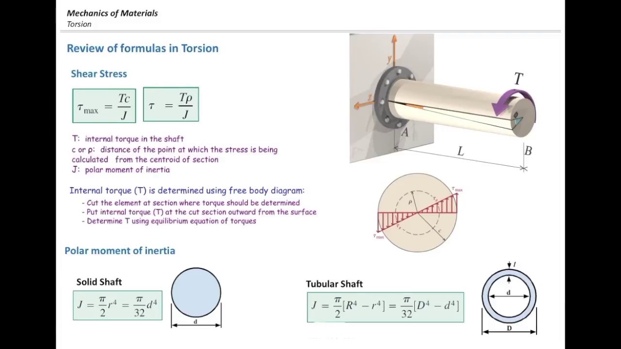
Torsional stress part2, Free body diagram and examples
1.5-3: Free body Diagrams with torque - YouTube Basic static equilibrium examples that emphasize drawing the free body diagram, choosing an axis, and evaluating torque without bothering to work out the num...
static equilibrium
Mechanics Map - Axial Force Diagrams and Torque Diagrams To create the torque diagram for a shaft, we will use the following process. Solve for all external moments acting on the shaft. Draw out a free body diagram of the shaft horizontally, rotating the shaft if necessary, so that all torques act around the horizontal axis. Lined up below the free body diagram, draw a set of axes.
Free Body Diagrams Archives - AP Physics C
Torque - Island Physics
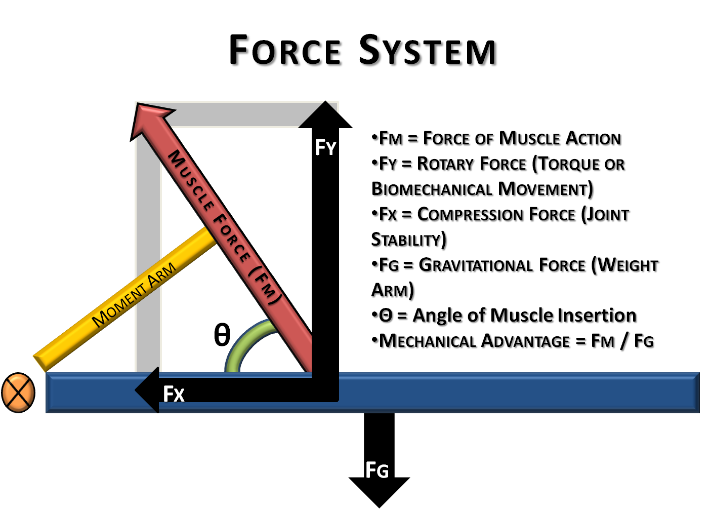
Basic Biomechanics: Moment Arm & Torque

Gears and Systems with both Rotation and Translation

File:Free Body diagram of Finger applying Torque on Cane.png ...
Free-Body Diagrams and Equilibrium
12.2 Examples of Static Equilibrium | University Physics Volume 1
11/1 Rotation, Torque Begin Rotational Dynamics Read Ch 9 ...
Solved You MUST draw a free-body diagram for the | Chegg.com

Torque ( Read ) | Physics | CK-12 Foundation

Torque Free Body Diagrams - Torque Project
Gyroscope Physics
free body diagram for pulley
Crank mechanism - inertia forces and crankshaft torque

Moments of INERTIA. Review of Inertia Inertia – Objects with ...
Chapter 9

Figure 9. Free body diagram of six-bar mechanism when torque ...

Belt and Pulley Devices, the Simple Answer.

T-T-T-Torque!: Free Body Diagram
![183_notes:torquediagram [Projects & Practices in Physics]](https://msuperl.org/wikis/pcubed/lib/exe/fetch.php?w=400&tok=e1cb61&media=183_notes:week12_torquediagrams1.png)
183_notes:torquediagram [Projects & Practices in Physics]
Chapter 8 Rotational Equilibrium and Rotational Dynamics Force
18 Free body diagrams, statics | Physics Forums
Mechanics Map - Axial Force Diagrams and Torque Diagrams
Questions on Torque - Torque Research Project
College Physics

*25. ssm A 1220-N uniform beam is attached to a vertical wall ...

Torque (article) | Khan Academy
0 Response to "42 free body diagram torque"
Post a Comment