40 push button starter switch wiring diagram
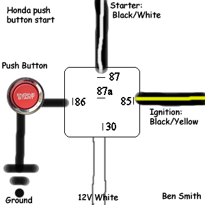
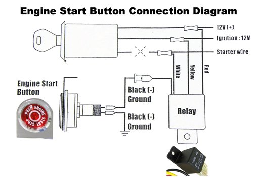
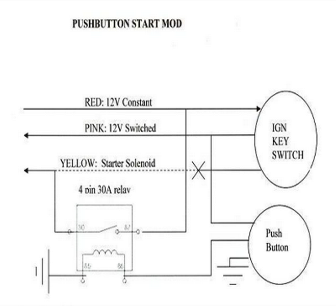
How to wire a 12V Ignition Switch Engine Start Push Button ... How to wire a 12V Ignition Switch Engine Start Push Button 3 Toggle Panel with Indicator Light - YouTube. How to wire a 12V Ignition Switch Engine Start Push Button 3 Toggle Panel with Indicator ... Wiring a push button start - TrackMustangsOnline.com - From the output of the push button, connect the Blue-White wire (start signal) You'll still have to put the key in the ignition because of the anti-theft system To start the car : - Flip up the master switch. That will power up the car like you turned the key all the way just before the cranking - Press the push button to start cranking.
Wiring Push Buttons Switch to Click PLC - Acc Automation Wiring to the Click PLC Start PB - X1 - Normally Open Stop PB - X2 - Normally Closed Selector Switch Hand Position - X3 Selector Switch Auto Position - X4 Start Green LED Lamp Output - Y5 Stop Red LED Lamp Output - Y6 Click PLC Program Operation - Push Buttons and Switches
Push button starter switch wiring diagram
Push button Ignition Switch Wiring Diagram New | Boat ... push button starter wiring diagram schematics wiring diagrams u2022 rh seniorlivinguniversity co Painless Wiring Push Button Start Push Button Switch. Find this Pin and more on Electrical by Dana Kittridge. Use a Push Button Switch with Arduino | Starting Electronics Arduino Push Button Switch Circuit Diagram The following image is a circuit diagram of the previous two breadboard circuits. R1 is a 10k resistor that pulls Arduino pin 2 to GND. With the switch S1 open, a voltage level of 0V is read on pin 2 by the Arduino. When the switch is closed, 5V is attached to pin 2 of the Arduino. Wiring a 240v motor to a push button on/off switch ... Hi, I've got a 1950's motor that i would like to wire to a push button on/off switch. Is the a push button switch on the market to do what i want in the diagram or a way of wiring one as i can not find any on ebay? The only ones i can find that is a close match is the 3 phase switches like this one (ebay No. 290930766073).
Push button starter switch wiring diagram. Wiring Diagrams - Push Button Switch Wiring Diagram ... Push Button Switch Wiring Diagram - 19mm push button switch wiring diagram, clipsal push button switch wiring diagram, momentary push button switch wiring diagram, Every electrical arrangement is composed of various diverse components. Each component should be placed and connected with different parts in specific way. If not, the structure will not work as it ought to be. Push Button Digital Potentiometer Circuit - Wiring Schemas ... To optionally build the physical circuit gather up your arduino uno board usb cable solderless breadboard an led resistors one from 100 1k ohms and one 10k ohm pushbutton and breadboard wires. Unit containing the push button switches is typically connected to the digital pot using pins cable and a connector or a bed of nails test system. Push Button Starter Switch Wiring Diagram - Wirings Diagram As stated earlier, the lines at a Push Button Starter Switch Wiring Diagram represents wires. At times, the wires will cross. But, it does not imply link between the wires. Injunction of 2 wires is generally indicated by black dot on the junction of two lines. There'll be primary lines that are represented by L1, L2, L3, and so on. Awesome Push Button Ignition : 5 Steps (with Pictures ... Turn the key to the "Engine On" position. Flip the switch on. Push the button. If you have wired everything all correctly you will start the engine. Now put your dash back together and put your buttons and switches wherever you like. You can drill holes in the dash and put the button and switch through there, or you can hide it under the dash.
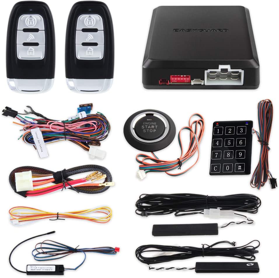
PDF Installation Instructions Push Button Start System 1. Connect Push Button Switch Harness Connectors to the Push Button Switch Terminals (See Figure 1). 2. Mount the Push Button Switch to an interior location in the vehicle. The switch has been designed to mount into a 7/8 inch diameter hole. 3. NOTE: The tan and gray wires are connected to the mating wires on the main wire harness. Emergency Push Button Wiring Diagram - Wiring Blog 35 Lovely Push Button Starter Wiring Diagram Diagram Wire Starter . Wiring Safety Relay And Emergency Button Relay Safety Emergency . Relay Contactor With Push Button On Off Control Electrical Circuit Diagram Electrical Diagram Relay . Control Three Phase Motor Starter With Start Stop Buttons Motor Control Electrical Panel . Electrical Diagrams ... Wiring Diagram For A Starter Controlling A 480v Motor With ... emolatur is offline push button for stop. One relay for control, and the motor. See image below for an example of 3 wire control being used to pull in a contactor to start a 3 phase motor. When you press the start button and the stop button. START-STOP CONTROL WIRING DIAGRAMS. Single Station with the starter.. PUSH BUTTON STATIONS. I. Voltage ... Push Button Switch Wiring Diagram - Wirings Diagram Push Button Switch Wiring Diagram - 19mm push button switch wiring diagram, clipsal push button switch wiring diagram, momentary push button switch wiring diagram, Every electric arrangement is composed of various unique parts. Each component ought to be set and linked to different parts in particular way. If not, the structure will not function as it should be.
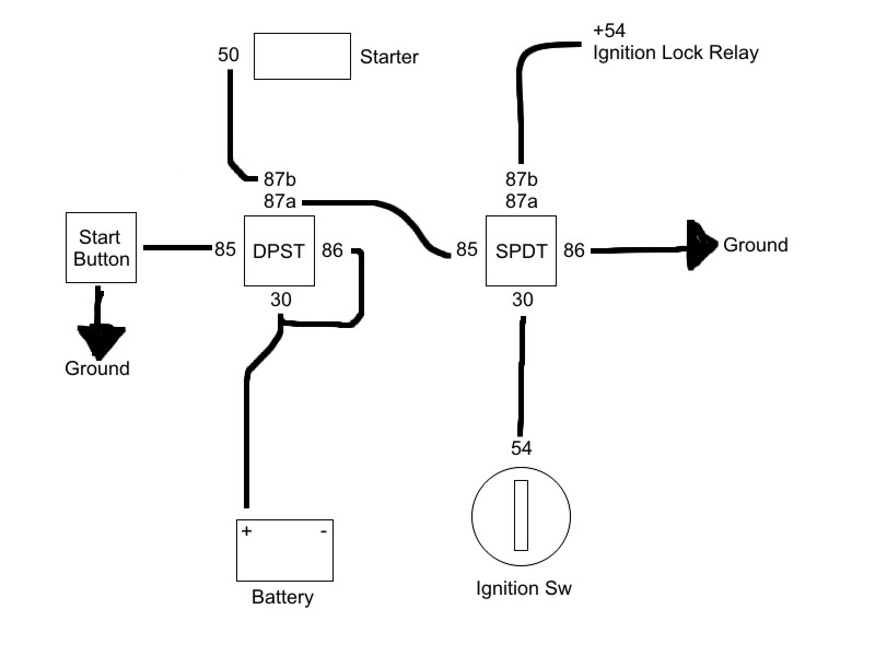
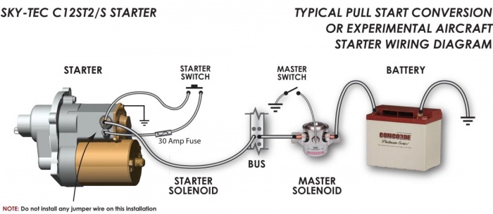
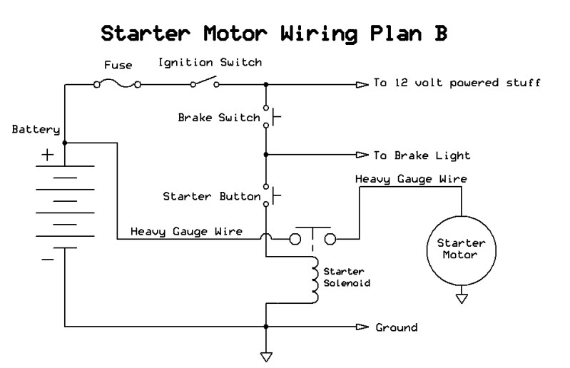
Push Button Start from SCRATCH - Hot Rod Forum A wire on the big post of the starter to one side of a push button, a wire from the little post on the starter to the other side of the push button. Then a wire from the positive side of the bat to a toggle and a ground running to the block for the toggle and the bat. PDF 800-2.0 Typical Wiring Diagrams for Push Button Control ... Typical Wiring Diagrams For Push Button Control Stations 5 Explanation of Symbols Momentary Contact Push Button - Auxiliary Contacts-Operate when Operating Coil of Contactor: Depressing button opens and parent switch does. In this case,M - Main Line S - Slow closes lower contacts. Releasing F normally open (N.O.) contacts close - Forward F Fast Light Switch Wiring Diagram: A Complete Tutorial | EdrawMax Following are some practical illustrations of the light switch wiring to make our minds and concepts more precise about what we have seen above.. Wiring a Single Pole Switch Source: This is the wiring of the single pole switch, in this case, the power source is with the switch, plus two wires are coming from the switch to the light. Push Button Starter Switch Wiring Diagram - Wiring Diagram Push Button Starter Switch Wiring Diagram Circuit Using 11N - Push Button Starter Switch Wiring Diagram Wiring Diagram contains numerous comprehensive illustrations that show the relationship of varied items. It contains instructions and diagrams for various kinds of wiring techniques and other things like lights, home windows, and so forth.
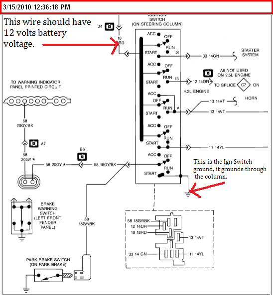
How to Wire Ignition Switch? - Rx Mechanic Here are the steps you need to take to wire the ignition switch yourself. However, depending on the vehicle in question, you might need a push-button starter switch wiring diagram. Step 1: Park the Vehicle. Ensure that your vehicle is parked on level ground before turning off the engine. Step 2: Ascertain the Terminals on the Ignition Switch
Push Button Switch Wiring Diagram - Wiring Diagram Push On Ignition Switch Wiring Diagram | Wiring Diagram - Push Button Switch Wiring Diagram. Wiring Diagram comes with several easy to stick to Wiring Diagram Guidelines. It is intended to aid all of the typical consumer in creating a suitable method. These guidelines will be easy to comprehend and use.
Start Stop Push Button Wiring Diagram - easywiring Use the top diagram to help you figure out how to wire it. Push button start stop switch wiring diagram electricity site push button starter switch wiring diagram. Pilot light l2 4 2 3 pilot light start stop bulletin 1495 normally closed auxiliary contacts are required.
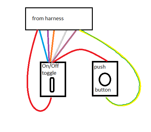
Simple wiring for toggle switch and push button start ... This is how to run wiring for a toggle on/off switch and a push button start. This is the most basic wiring you need to run your mower.
DIY: push start button ( wiring diagram) | Page 9 | 8th ... the time it takes to do the install of course depends on your own skill level with interior parts... i installed mine at separate times... ie: i put the button on and never wired it at: that part maybe took about 1-2hrs (damn cutting the dash so clean is what i was concerned with )... the wiring part took ummm about 1hr b/c i did it at night and had a mini LED flashlight...
Wiring Diagram Contactor With Momentary Start Stop Pdf Wiring diagrams do not show the operating mechanism since it is not electrically controlled. stop ol m start 3 start start fiber optic transceiver class type ft fiber optic push button, momentary contact push buttons - maintained contact pilot lights instant operating contacts timed contacts contactor breakers limit switch, n.o., static control.
Wiring a 240v motor to a push button on/off switch ... Hi, I've got a 1950's motor that i would like to wire to a push button on/off switch. Is the a push button switch on the market to do what i want in the diagram or a way of wiring one as i can not find any on ebay? The only ones i can find that is a close match is the 3 phase switches like this one (ebay No. 290930766073).
Use a Push Button Switch with Arduino | Starting Electronics Arduino Push Button Switch Circuit Diagram The following image is a circuit diagram of the previous two breadboard circuits. R1 is a 10k resistor that pulls Arduino pin 2 to GND. With the switch S1 open, a voltage level of 0V is read on pin 2 by the Arduino. When the switch is closed, 5V is attached to pin 2 of the Arduino.
Push button Ignition Switch Wiring Diagram New | Boat ... push button starter wiring diagram schematics wiring diagrams u2022 rh seniorlivinguniversity co Painless Wiring Push Button Start Push Button Switch. Find this Pin and more on Electrical by Dana Kittridge.












0 Response to "40 push button starter switch wiring diagram"
Post a Comment