40 ts diagram for air
Goodman Diagram - an overview | ScienceDirect Topics The stress range diagram defined above is the Goodman diagram for fiberglass sucker rods and is used for the same purposes as the modified Goodman diagram for steel rods. Figure 3.72 gives this diagram for Fiberflex rods [84].These rods have a maximum allowable static load of 35,000. psi at a temperature of 160 F.. It can be observed that an increase in temperature or in … TS 4000 EN 1-6 - GEZE TS 4000 EN 1-6 Closing force in accordance with EN 1154: EN 1 - 6 Barrier-free in accordance with DIN 18040 up to leaf width (max.) in mm
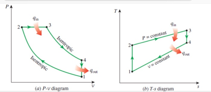
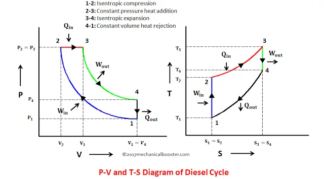
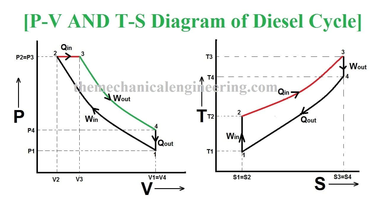
Diesel Cycle - Process with P-V and T-S Diagram ... Diesel Cycle - Process with P-V and T-S Diagram. The diesel cycle was invented by Rudolph Diesel in 1893. He put forward an idea by which we can attain higher thermal efficiency, with a high compression ratio. All diesel engine works on this cycle. Diesel is used as fuel in this cycle as it can be compressed at higher compression ratio.
Ts diagram for air
Longitudinal Wave - Definition, Examples, Formula, Diagram Longitudinal waves are the mechanical waves in which the vibration of the particles takes place in the same direction as that of the wave. Sound waves, seismic waves are the examples of longitudinal waves. Stihl TS 420 A Disc Cutter (TS 420 A) Parts Diagram, Air ... Stihl Diagrams TS 420 A Air Filter Stihl TS 420 A Disc Cutter (TS 420 A) Parts Diagram, Air Filter Look at the diagram and find parts that fit a Stihl TS 420 A Disc Cutter, or refer to the list below. All parts that fit a TS 420 A Disc Cutter Select Page Mecholic: Air Refrigerator Working On Bell-Coleman Cycle ... Fig show P-V and T-S diagram of bell coleman refrigerator. Here P 1, V 1, T 1, S 1 represents the pressure, volume, temperature, entropy of air respectively at point 1. And so on. It represents the corresponding condition of air when it passed through the component. 1-2: Isentropic Compression The Air drawn from refrigerator to air compressor cylinder where it compressed isentropically ...
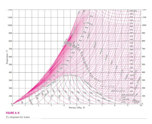
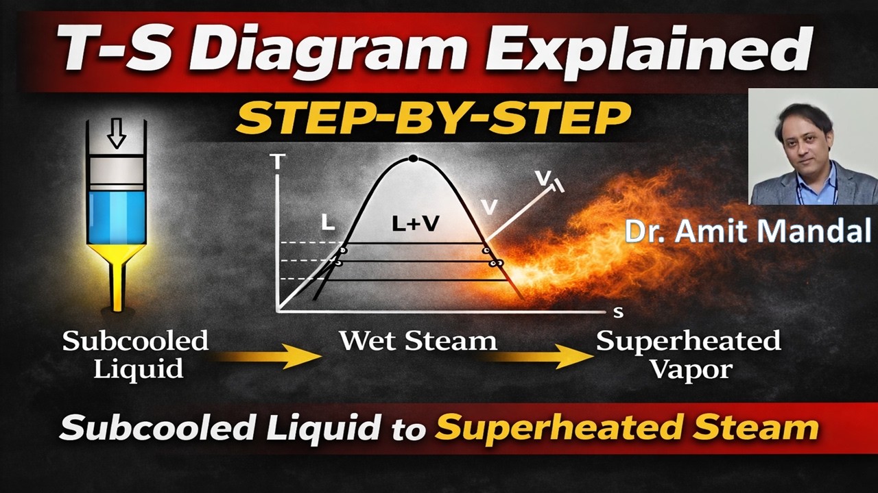
Ts diagram for air. Temperature Entropy (T-s) Diagram - Thermodynamics ... A T-s diagram can be constructed for any pure substance. It exhibits the same features as P-u diagrams. Temperature Entropy (T-s) Diagram In the liquid-vapor region in Figure 13, water and steam exist together. For example, at point A, water with an entropy (s f) given by point B, exists together with steam with an entropy (s g) given by point C. Stirling Cycle: Efficiency with P-v and T-s Diagram The p-v and t-s diagrams of this cycle are shown in the figure. Let us now consider the four stages of the Stirling cycle. Let the engine cylinder contain m kg of air at its original position represented by point 1. At this point, let P1, T1, and V1 be the pressure, temperature, and volume of the air respectively. What is Otto Cycle - P-V and T-S Diagram Easiest ... Here we will try to understand this cycle with help of its P-V and T-S diagram. The four processes of this cycle is as follows: 1. Isentropic ( reversible adiabatic) compression 2. Constant volume (Isochoric) heat addition 3. Isentropic (reversible adiabatic) Expansion 4. Constant volume heat rejection. PDF Entropy-temperature and transmission diagrams for air for air, Fig. 1, was designed by the writer several years ago. Recently, Mr. John A. Dent, Instructor in Mechanical Engineering, simplified the construction of this chart and improved it by the addition of a series of lines representing the curves of pv'= C, as shown by Fig. 2. Fig. 5
Brayton Cycle | Efficiency, P-V & T-S Diagrams | Heat ... Below are P-V and T-S Diagrams of the Brayton (or Joule) Cycle. Brayton Cycle is comprised of four processes Process 1-2 It is isentropic compression process. Here a little rise in the temperature of gas occurs due to compression. Since it is a compression process, volume of the gas decreases. Process 2-3 It is isobaric heat addition process. Ts Diagram Of Air.pdf [en5zkdq9vpno] - idoc.pub Ts Diagram Of Air.pdf [en5zkdq9vpno]. ... THERMODYNAMIC PROPERTIES FIG. 2-5 Temperature-entropy diagram for air. [Landsbaum, Dadds, Stevens, et al., Am. Inst. Chem ... FITNESS FOR AIR TRAVEL - Air Canada point (hip or waist) as shown on diagram at right. 3. Mark the touch point between the ruler and the paper as Point A. 4. Rest a ruler or straightedge on the right side of patient at the ... Call the Air Canada Medical Assistance Desk at 1-800-667-4732 and provide your booking Moist Air - the Mollier Diagram - Engineering ToolBox Air is a mixture of mostly oxygen, nitrogen and water vapor. The Mollier diagram is a graphic representation of the relationship between air temperature, moisture content and enthalpy, and is a basic design tool for building engineers and designers. The Mollier diagram is a variant of the psychrometric chart.
Aircraft refrigeration system (air cooling system) FIG:-T-S DIAGRAM FOR SIMPLE AIR CYCLE COOLING SYSTEM For any query contact at ripuranjansingh999@gmail.com 6. IF V IS THE AIRCRAFT VELOCITY OR THE VELOCITY OF AIR RELATIVE TO THE AIRCRAFT IN METERS PER SECOND, THEN KINETIC ENERGY OF OUTSIDE AIR RELATIVE TO AIRCRAFT, From the energy equation, we know that 2000 v hh 2 12 2000 V T.cT.c 2 1p2p p 2 ... Rankine Cycle - Ts, Pv Diagrams, Reheat, Equations ... The general efficiency equation of the simple Rankine cycle, Thermal efficiency = W Turbine - W Pump / Q Boiler. Where, W Turbine is the work output. W Pump is work input. Q Boiler is the heat supplied. Let's consider the followings, h 1: Enthalpy at point 1. h 2: Enthalpy at point 2. P-V and T-S Diagrams - NASA The area under a process curve on a T-s diagram is related to the amount of heat transferred to the gas. It is possible to perform a series of processes, in which the state is changed during each process, but the gas eventually returns to its original state. Such a series of processes is called a cycle and forms the basis for understanding engines. Diesel Cycle: Definition, Process, PV and TS Diagram ... When air is entered the piston moves TDC to BDC Bottom dead center. During the suction process, the inlet valve is open and the exhaust valve is closed. As you can see in the diagram. Compression Process: The compression is the second process in which the air is entered into the cylinder will be compressed along with the fuel.
Solved] As shown in (a) P-v diagram and (b) T-s diagram, an ...
Diesel cycle: Definition, PV and TS diagram, Equations ... Diesel cycle PV and TS diagram: The diesel cycle can be plotted on PV and TS plot as shown below, Each process of the diesel cycle is described as, Process 1-2:- Isentropic compression ... In this process, the pressure of the air is reduced from `P_{3}` to `P_{4}` and the volume increases from `V_{3}` to `V_{4}`.

4. Aircraft Refrigeration System
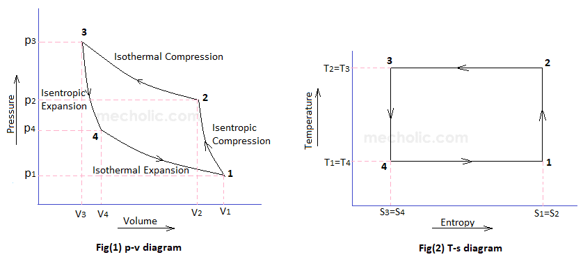
Bell Coleman Cycle with PV and TS diagram - Mechanical Walkins Bell Coleman Cycle with PV and TS diagram Thermodynamics Uncategorized August 11, 2019 Rashid The Bell Coleman Cycle is a refrigeration cycle where the working fluid is air which is compressed and expanded but do not change state. This cycle is the modification of reverse Carnot cycle.
Solved 1. Figure 1 shows the P-V and T-s diagrams for an ...
Example 7D - 3: Work, Efficiency and the T-S Diagram for ... Air contained in a piston-and-cylinder device undergoes a power cycle made up of three internally reversible processes. Step 1-2: Adiabatic compression from 20 psia and 570 o R to 125 psia: Step 2-3: Isothermal expansion to 20 psia Step 3-1: Isobaric compression a.) Sketch the process path for this power cycle on both PV and TS diagrams b.) Calculate T 3 in o F: c.) Calculate the boundary work ...

METBD 330: Thermodynamics, Chapter 7
Dual cycle: Definition, Process, Formula, Pv & Ts Diagram ... W 1−2 = Cv(T 1 − T 2) W 1 - 2 = C v ( T 1 - T 2) Process 2-3: Constant volume heat addition. For the isochoric process, Change in volume ( δv = 0 δ v = 0) ∴ W 2−3 = 0 ∴ W 2 - 3 = 0. Here temperature rises from T 2 T 2 to T 3 T 3. Hence change in internal energy is given by,

Simple Air Evaporative Cooling system
COP Of Air Refrigerator Working On Reversed Carnot Cycle ... Fig (1) and fig (2) shows the p-v and T-s diagram of a refrigeration system working on reversed Carnot cycle. The process involved in reversed Carnot cycles are as follows 1-2. isentropic compression process During this stage, air is compressed isentropically. Pressure and temperature increases, the specific volume of decreases.
P-V and T-S Diagrams
Air T-s Diagram - EnTEs Air T-s Diagram Diagrams Air, Gas, Temperature Entropy, T-s, Diagram, Chart Temperature, Pressure, Specific Volume, Specific Internal Energy, Specific Enthalpy, Specific Entropy, Specific Exergy, Exergy Ratio Density, Isobaric Specific Heat, Isochoric Specific Heat, Ratio of Specific Heat, Velocity of Sound Air T-s Diagram :

Brayton Cycle with Reheat, Regeneration and Intercooling
Importance of Significance: Functions, Diagram - Embibe Economic Importance. Source of Food: Biodiversity is important to provide food to all living organisms in this ecosystem. Agriculture is a source that provides food for human beings, trees, and plants to animals. Other small organisms also get their food from different food sources available in this ecosystem.

TS diagram of Air.pdf - PDFCOFFEE.COM
Thermal Efficiency - Brayton Cycle | Equation - Nuclear Power Brayton Cycle - Ts diagram. Isentropic compression - ambient air is drawn into the compressor, pressurized (1 → 2). The work required for the compressor is given by W C = H 2 - H 1. Isobaric heat addition - the compressed air then runs through a combustion chamber, burning fuel, and air or another medium is heated (2 → 3).

P-V and T-S diagrams of a standard air Brayton cycle ...
Air conditioning- Types, Diagram, Working, Applications The complete process of air conditioning includes the following processes. 1. Cooling or heating air 2. Addition of moisture in the air (Humidification) or removal of moisture from the air (Dehumidification) 3. Controlling movement of air 4. Purification of air 5. Addition of fresh air from outside 6. Distribution of air

3. T-s diagram for the two-stage air compressor | Download ...
PDF Chapter 10 Refrigeration & Heat Pump Cycles (Systems) • Two significant effects are apparent from the Ts diagram: (1) for the single cycle - the compressor work is increase by area 2->a->6->5->2. (2) there is a decrease in the refrigeration capacity when a single unit is used => 4->b->d->c->4. • For the double-cascade system shown, it is important that the triple-state
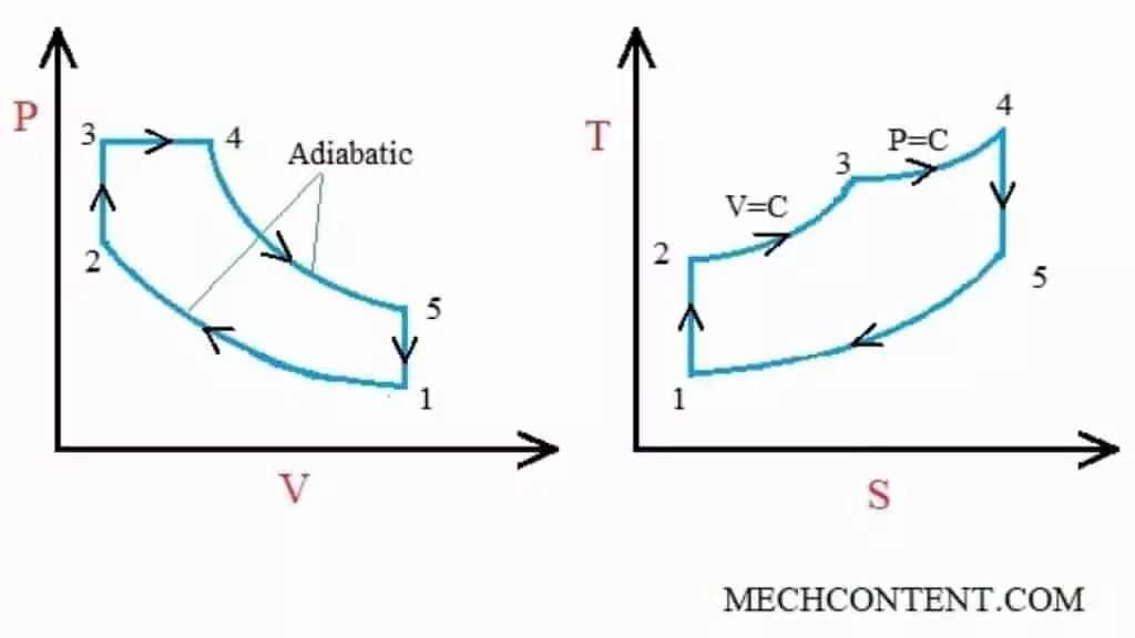
Dual cycle: Definition, Process, Formula, Pv & Ts Diagram ...
Brayton Cycle - Definition, Meaning, Efficiency, Ts, Pv ... Brayton cycle parts Ts diagram There are four main components, Compressor (C) Combustor or Combustion Chamber (CC) Turbine (T) Heat Exchanger (HE) Compressor The compressor draws the ambient air Compression happens, which means pressure & temperature is increased Combustor Basically fuel injection is done in the combustor or mixing chamber

b): T-S Diagram of Claude's Air Liquefaction Process ...
What is Brayton Cycle - Gas Turbine Engine - Definition Brayton Cycle - Ts diagram. isentropic compression - ambient air is drawn into the compressor, where it is pressurized (1 → 2). The work required for the compressor is given by W C = H 2 - H 1. isobaric heat addition - the compressed air then runs through a combustion chamber, where fuel is burned and air or another medium is heated ...

A two-stage air compressor operates at steady state ...
Epithelial Tissue: Structure with Diagram, Function, Types ... Epithelial Tissue Functions. Protection: As it covers the entire body surface, it is the first line of defence against any kind of mechanical injury, chemical exposure, excessive fluid loss and infections. Ciliary projections present in the nose or upper respiratory tract, trap the dust particles and prevent it from entering the body
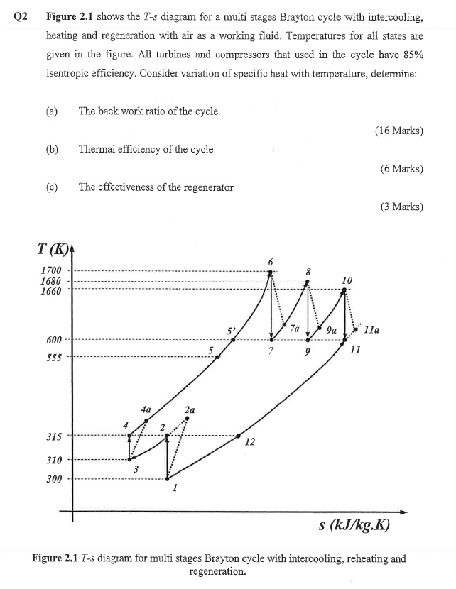
Solved Q2 Figure 2.1 shows the T-s diagram for a multi ...
TS diagram for the air standard Otto cycle | Download ... A PV diagram of the air standard Otto cycle is shown in Figure 2. The constant-volume process is thermodynamically efficient and, in principle, a feasible cycle. In contrast to the Carnot process,...

T-s diagram for volatile fluid in air storage unit (For ...
Diagram Fasa Air dan Penjelasannya - Materi Kimia Pada tekanan 1 atm (760 mmHg), air membeku pada 0°C. Pada tekanan 4,58 mmHg, air membeku pada 0,0099°C. Titik B menyatakan titik tripel (titik dimana pada suhu dan tekanan tersebut terjadi kesetimbangan fasa antara gas, cair, dan padat secara bersama-sama) Titik tripel air sebesar 0,0098°C pada 4,58 mmHg.

White Brook Solutions
Ts-diagram showing a transcritical R744 air-conditioning ... Download scientific diagram | Ts-diagram showing a transcritical R744 air-conditioning cycle without internal heat exchange from publication: A Thermodynamic Property Chart as a Visual Aid to ...

Air cycle combined heating and cooling for the food industry ...
WINEGARD Gateway B. Air 360+ In Dome Install see page 8 for diagram If the compatible Air 360+ system was installed at the RV manufacturer and there isn’t a white circular Winegard cable access cap on the RV’s ceiling, the Gateway was meant to be installed inside the dome of the Air 360+. If

T-s diagrams for two subcycles. (A) T-s diagram for HP cycle ...
Design of Vapor-Compression Refrigeration Cycles Figure 4 shows the T-s diagrams for two refrigeration cycles, one where S4 is a saturated vapor and the other (in light green) where S4 has been moved further into the saturation dome to allow S1 to be a saturated vapor. Figure 4: T-s diagram for different compressor conditions
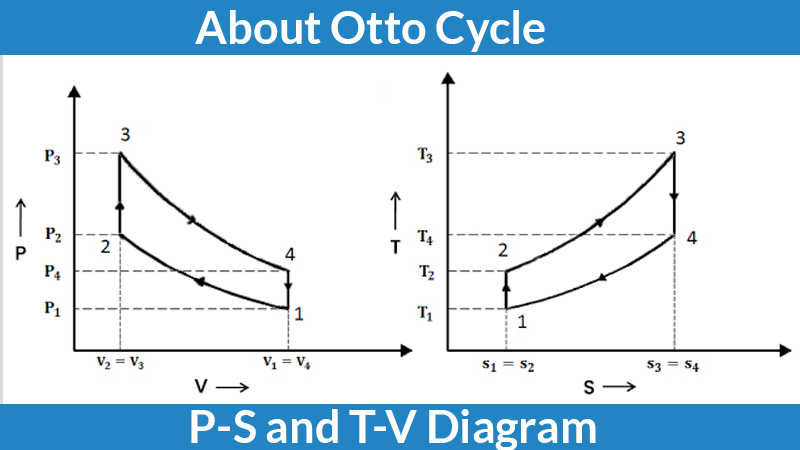
Otto Cycle | What is Otto cycle P-V and T-S Diagram? - Unbox ...
Mecholic: Air Refrigerator Working On Bell-Coleman Cycle ... Fig show P-V and T-S diagram of bell coleman refrigerator. Here P 1, V 1, T 1, S 1 represents the pressure, volume, temperature, entropy of air respectively at point 1. And so on. It represents the corresponding condition of air when it passed through the component. 1-2: Isentropic Compression The Air drawn from refrigerator to air compressor cylinder where it compressed isentropically ...

Air T-s Diagram
Stihl TS 420 A Disc Cutter (TS 420 A) Parts Diagram, Air ... Stihl Diagrams TS 420 A Air Filter Stihl TS 420 A Disc Cutter (TS 420 A) Parts Diagram, Air Filter Look at the diagram and find parts that fit a Stihl TS 420 A Disc Cutter, or refer to the list below. All parts that fit a TS 420 A Disc Cutter Select Page

Otto Cycle - an overview | ScienceDirect Topics
Longitudinal Wave - Definition, Examples, Formula, Diagram Longitudinal waves are the mechanical waves in which the vibration of the particles takes place in the same direction as that of the wave. Sound waves, seismic waves are the examples of longitudinal waves.

T-S diagram of Vapour compression cycle | Download Scientific ...

T-s diagram

Ts-diagram showing a transcritical R744 air-conditioning ...

Ch10, Lesson E, Page 5 - TS Diagram for the Regenerative Cycle
COP Of Air Refrigerator Working On Reversed Carnot Cycle with ...

Atkinson Cycle - Thermodynamics Cycle

TS diagram for the air standard Otto cycle | Download ...
Refrigeration & Liquefaction

Ch10, Lesson E, Page 2 - Cold Air-Standard Assumptions
Diesel Cycle – Process with P-V and T-S Diagram - Mechanical ...
Solved 4. Use the temperature entropy diagram provided to ...
TS diagram of water
Diesel Cycle: Definition, Process, PV and TS Diagram ...

Ch7, Lesson B, Page 9 - T-S Diagram for Water
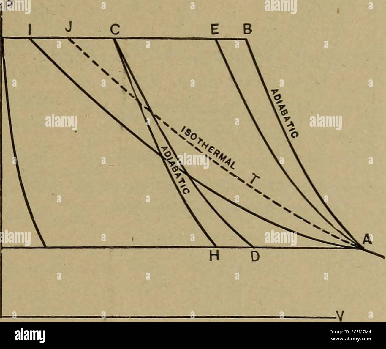
Applied thermodynamics for engineers. ts. 219. Comments. As ...
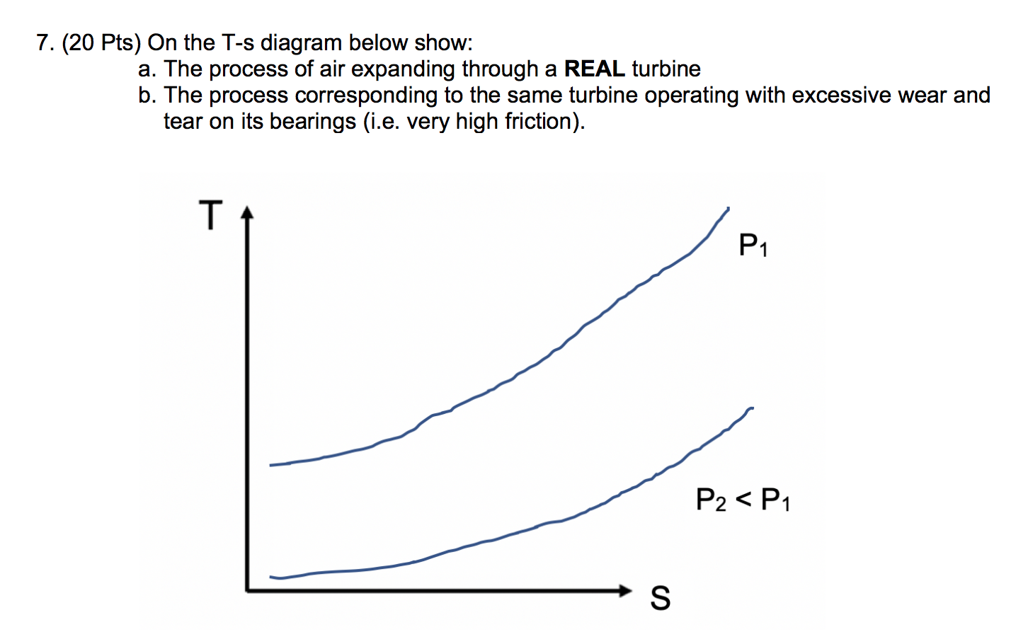
Solved 7. (20 pts) On the T-s diagram below show: a. The ...

Ideal Rankine Cycle

T-S Diagram Uap Air | PDF

Enthalpy - Wikipedia
0 Response to "40 ts diagram for air"
Post a Comment