40 lng process flow diagram
LNG and Liquefaction - Cameron LNG. Liquefied natural gas (LNG), is natural gas that is super-cooled to minus 260 degrees Fahrenheit (minus 162 degrees Celsius). At that temperature, natural gas transforms from a gaseous state into a liquid. When in liquid form, natural gas takes up to 600 times less space than in its gaseous state, making it ... Animation showing how Woodside produces liquefied natural gas (LNG) for customers in the Asia-Pacific region and beyond.Find out more at http://www.woodside....
processing and Chart's process expertise and proven experience in providing integrated NRU systems that enrich and recover helium is highly regarded by companies around the world seeking to exploit their valuable helium resources. Liquefied Natural Gas Chart is developing the LNG infra-structure right across

Lng process flow diagram
Liquefied Natural Gas (LNG) is used for transporting natural gas (NG) to distant markets, not supplied by NG grid connecting the extraction/production point to the users. Basically the LNG process is composed by the following steps[1]: Extracted natural gas is liquefied in the production field or in a close site, after removing the impurities. Regasification process involves raising the temperature of the LNG using seawater. The LNG gas is passed through a heat exchanger using sea water. Some LNG terminals also use turbine flue gases from their energy recovery systems. LNG is thus converted into gaseous state by heating at a temperature greater than 0 degree Celsius. processing capacity of 4 MMtpa of LNG, and using ORV (Open Rack Vaporizer) and SCV (Submerged Combustion Vaporizer), which are the dominant regasification technologies today. It includes the process flow diagram, material balance, major equipment sizes, and specifications. Cost
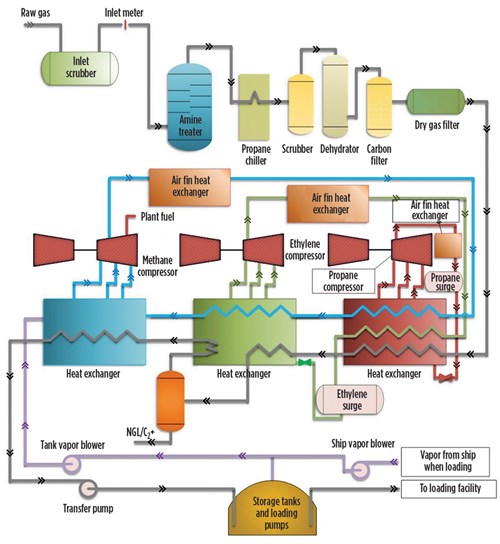
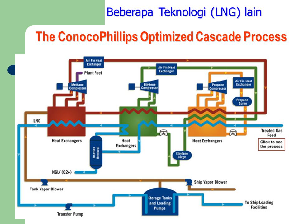
Lng process flow diagram. Download scientific diagram | Flow diagram of LNG process from publication: Carbon footprint assessment of Western Australian LNG production and export to the Chinese market | In reviewing the ... storage tanks, which takes approximately 14-16 hours. The LNG remains at -160°C for the duration of the process. LNG has been transported commercially by ships since 1964 and as of the end of 2016 there have been 88,000 cargoes or 176,000 voyages without an LNG loss. T. ransPorTaTion. A 155,000 m. 3. membrane vessel is approximately the same ... Liquefied Natural Gas and Liquefied Hazardous Gas • 49-CFR-193 LNG Facilities: Federal Safety Standards • NFPA 59A Standard for the Production, (2001) Storage and Handling of LNG LNG Process Safety LNG Gabriel Castaneda, P.E. 49-CFR-193 is based on NFPA 59A, 2001 Optimized cascade process. The optimized cascade process (OCP) is a simple and reliable technology. A process flow diagram for the OCP is shown in Fig. 6. In this process, three pure-component refrigerants (namely propane, ethane and methane) are used at different pressures during the refrigeration and liquefaction processes.
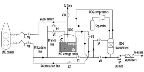
LNG Dehydration(Drying of Natural Gas) Absorption and refrigeration with hydrate inhibition is the most common dehydration process used to meet pipeline sales specifications. ... Insensitive to moderate changes in gas temperature, flow rate, and pressure. They are relatively free from problems of corrosion, foaming, etc. The following is a general guideline for the startup for an LNG production plant. A generic C3MCR liquefaction train process flow diagram is shown in Figure 7-2.Startup of other liquefaction technologies may be slightly different. II. The Process A simplified process flow diagram is shown in Figure 1. Figure 1 – LNG Receiving Terminal Simplified Process Flow Diagram The LNG receiving terminal receives liquefied natural gas from special ships, stores the liquid in special storage tanks, vaporises the LNG, and then delivers the natural gas into a distribution pipeline. LNG plant normal operation . Molecular sieve unit: Designed to meet the product specifications on water and mercaptans (RSH) content. The main items that should be checked in this unit: • Mercaptans buildup • Regeneration gas temperature • Flow rate • Flow channeling • Oxygen • Inlet separator • Bed fouling • Dehydratation bed ...
Download scientific diagram | Process flow diagram of the FLNG system from publication: Bayesian network-based failure analysis of fire safety barriers in floating LNG facility | Fire accidents on ... -Onshore LNG vs. FLNG, baseload plants vs. tolling facilities •Market views / growth of LNG -Industry statistics, project forecasts, and LNG news •Review of liquefaction projects and process technologies -History, size, and growth of LNG trains and complexes -Licensor share, process selection, cycle efficiency, equipment, etc. Process Flow Diagram, discussed in Chapter 1. Once a PFD is released for detail design, the project scope has been established and P&ID development may commence. P&IDs develop in steps. The key members of the design team - perhaps plant design, piping, process, and project specialists, all lay out a conceptual pass at Download scientific diagram | 6 Block Flow Diagram of an LNG plant. from publication: Simulation and integration of liquefied natural gas (lng) processes ...
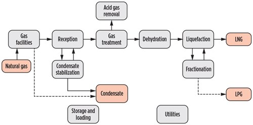
Figure 8: Process flow diagram of R410a precooling-nitrogen expansion liquefaction cycle (He & Ju, 2015) Natural gas flows through two heat exchangers; the first HEX cools the gas down from ambient conditions to -44ºC, where after the second cryogenic HEX produces LNG at -160ºC.

This Guide has been developed to provide guidance for the design, construction, and survey of Liquefied Natural Gas (LNG) vessels utilizing regasification systems. The Guide focuses on systems and arrangements ... • Process Flow Diagram (PFD) • Piping arrangement • Pipe stress analysis (high pressure and cryogenic) ABS.

improves process efficiency. Another advantage of using BAHXs in MR processes is the ability to scale capacity. BAHXs work well in both small and multi-train mid scale LNG applications as capacity can be easily managed for increasingly larger flow volumes. The construction of Figure 6. IPSMR® mixed refrigerant process technology scheme.
Liquefied Natural Gas (LNG) is Natural Gas that has been cooled to –260° F (–162° C), changing it from a gas into a liquid that is 1/600th of its original vo...
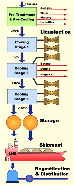
Liquefaction Process A block flow diagram of the liquefaction process is shown in Figure 2. The first step in the process is removal of acid gases such as carbon dioxide (CO2) and hydrogen sulfide (H2S). CO2 would freeze at cryogenic process temperatures and H 2S must be removed to meet the LNG product specifications. Typical specifications for

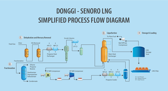
A simplified schematic of the LNG process is shown in Figure 6.4. Although similar, the liquefaction process varies depending on the powering option adopted for the LNG plant - all mechanical drive or all electrical power. Figures 6.5 and 6.6 show simplified process flow diagrams for the plant for the mechanical drive and electrical power options
•At atmospheric pressure LNG has a temperature of about –162ºC •LNG contains about 85-95 % methane •LNG is colorless, odorless, non-corrosive and non-toxic •Evaporated LNG can displace oxygen and cause human suffocation •Flammability range, 5-15 vol % concentration in air •Autoignition temperature, 540 C 5 LNG is a cryogenic liquid
A third safety step is taken in the liquefaction process where molecules of water, which accompany the natural gas in the feed, are condensed and flashed in the stage of natural gas pre-cooling. The third stage is the Hg removal. Hg causes corrosion in the expensive Aluminum LNG heat exchangers used in the liquefaction process. For example, 10 ...
After making simple simulations mimic real process, variables were transferred to real process simulation. Optimization- Refrigerant composition . Optimization- Compressor work. Restriction needed- Heat transfer area. All cells in LNG HX must have equal area. Restriction needed- Second law of thermodynamics. Check temperature of streams. Utilities
Hammerfest LNG plant - block flow diagram. Slug catcher. Inlet facilities/ ... process. – Typical requirements for LNG: Max 50 ppmv CO2, Max 4 ppmv H2S.28 pages
Liquified Natural Gas: Properties, Uses, Origin, Composition, LNG Process. Liquefied Natural Gas or LNG is natural gas with the primary element as methane. The Liquefied Natural Gas is converted to liquid form for ease of transport and storage. While in liquid form, Liquified Natural Gas takes up around 1/600 th of the volume of its gaseous form.
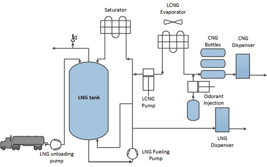
Typical Process Diagram for Small LNG Regasification (Part 1) August 2, 2016 December 18, 2018 Rifka Aisyah LNG. Today I want to share you Typical Process Diagram for Small LNG Regasification. For your information, small LNG regasification is very useful to be built in remote location where power supply is very limited.

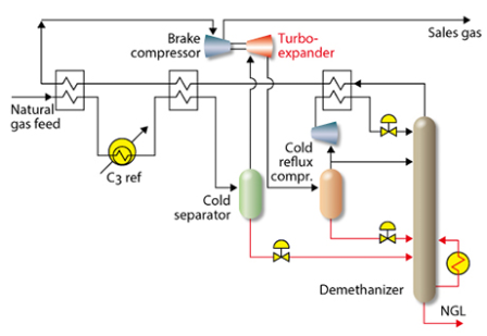
Flow diagram of the APX process. ... In a typical LNG process, a Joule-Thompson valve is used to reduce pressure in refrigeration units. Recently, however, liquid expanders have been introduced in new liquefaction plants. The liquid expanders function like pumps in reverse. Liquid enters at a higher pressure and leaves at a lower pressure.
processing capacity of 4 MMtpa of LNG, and using ORV (Open Rack Vaporizer) and SCV (Submerged Combustion Vaporizer), which are the dominant regasification technologies today. It includes the process flow diagram, material balance, major equipment sizes, and specifications. Cost
Regasification process involves raising the temperature of the LNG using seawater. The LNG gas is passed through a heat exchanger using sea water. Some LNG terminals also use turbine flue gases from their energy recovery systems. LNG is thus converted into gaseous state by heating at a temperature greater than 0 degree Celsius.

Liquefied Natural Gas (LNG) is used for transporting natural gas (NG) to distant markets, not supplied by NG grid connecting the extraction/production point to the users. Basically the LNG process is composed by the following steps[1]: Extracted natural gas is liquefied in the production field or in a close site, after removing the impurities.


0 Response to "40 lng process flow diagram"
Post a Comment