40 ro check valve diagram
6. All pumps are shown with isolation flanges or full port ball valves for isolation. The alternative is standard flanges with full port ball valves and a separate flow check valve. 7. Install a minimum of 12 diameters of straight pipe upstream of all circulators and check valves. 8. 6:41http://modularhydro.comThis video shows you how to install the automatic shut off valve for a reverse osmosis ...26 Oct 2012 · Uploaded by ModularHydro
Check Valve: If the check valve breaks, it prevents the RO system from attaining the shut-off pressure. So, more water will be flowing down the drain line. To solve this problem, you need to replace the check valve with a new one.
Ro check valve diagram
Replacement of the reverse osmosis component:This reverse osmosis system contains a replaceable component critical to the efficiency of the system. Replacement of the reverse osmosis component should be with one of identical specifications, as defined by the manufacturer, to assure the same efficiency and contaminant performance. 14" Check Valve - How They Work. Figure 1: Check valve. A check valve is a device that only allows the flow of fluids in one direction. They have two ports, one as an inlet for the media and one as the output for the media. Since they only allow media flow in one direction, they are commonly referred to as 'one way valves' or 'non return ... Piloted check valves HGL Data sheet – Push-in connector Function-M-Flow rate 130 ... 1400 l/min-Q-Temperature range –10 ... +60°C-L-Operating pressure 0.05 ... 1 MPa The piloted check valve is suitable for brief positioning and braking functions in pneumatic drives. Compressed air flows to and from the drive as long as a control signal is
Ro check valve diagram. valves and riser tubes. In some cases, older plumbing may use a larger size shut-off and riser tube. In this case, it would be necessary to either replace the old valve and riser tube with new 3/8" parts, or use an alternative connection to draw the water supply to the reverse osmosis system. Alternatives Direct the purified RO/DI water from the BLUE line into a sink or drain. 3. Turn on the household water supply. 4. Allow the system to run for one hour to flush dusty fines from carbon blocks and preservatives from the RO Membrane. This is a good time to check all fittings and connections for leaks. 5. Solenoid valve for RO water purifier. Normally solenoid valves for RO water purifiers (reverse osmosis systems) are of 2/2 way (1 inlet, 1 outlet of the open/closed type), ideal for water ON/OFF control. There are three types of solenoid valves: Direct operated fluid solenoid valves. Direct acting solenoid valves have a compact design. 2:12An automatic shut off valve controls the water entering your reverse osmosis system. It shuts off the incoming ...11 Dec 2020 · Uploaded by iSpring Water Systems
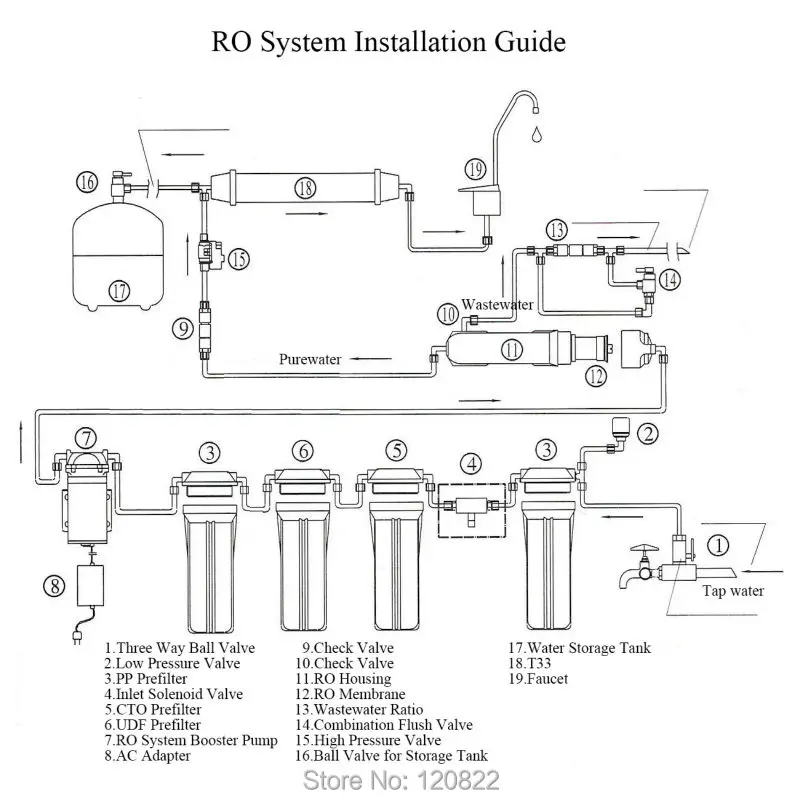
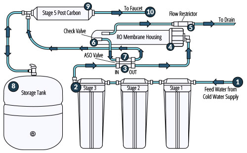
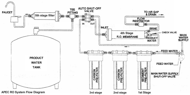
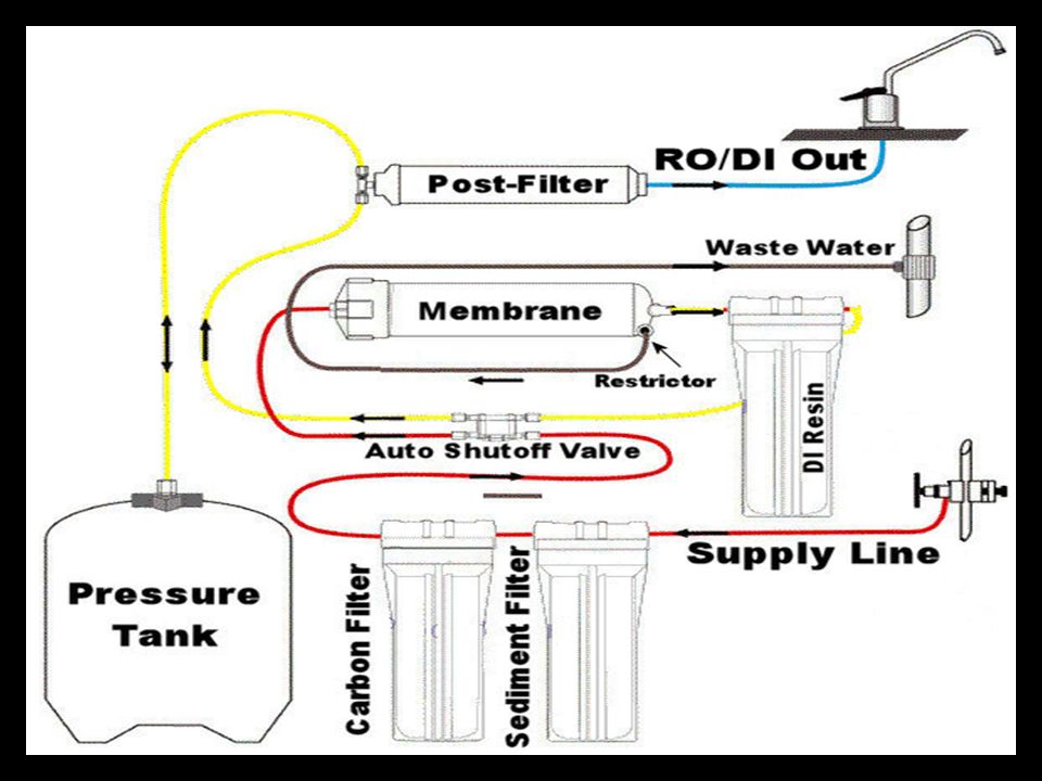
Installation Diagram of 4 Stage Reverse Osmosis Systems. The 3 stage, 4 stage and 5 stage reverse osmosis systems install exactly the same. The only difference is the addition of a carbon water filter before the membrane on the 4 stage RO system and two of them on the 5 stage system. 2:35Transcript · Next: · Automatic Shut Off (ASO) Installation · How to Install an Automatic Shutoff and Check ...9 Jul 2015 · Uploaded by US Water Systems 3:02How to Replace Automatic Shut Off Valve in Reverse Osmosis Drinking Water SystemPlease share this ...9 Apr 2016 · Uploaded by Gary the Water Guy *Diagram 5 Stage RO+UV w/Booster* This is a diagram of a 5 stage Reverse Osmosis system with a UV light and a booster pump. Click on the link *Diagram 5 Stage RO+UV w/Booster* and you will be transferred to the diagram. There is additional information about installation of a RO system on this web site.
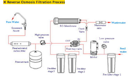
supply laboratory sinks and equipment, typically know as Reverse Osmosis/De-ionized (RO/DI) systems. This guideline also addresses RO make-up for clean steam humidification systems and soft water make-up for boilers. Related Sections U-M Design Guideline Sections: 230000 - Basic Mechanical Requirements U-M Master Specification Sections: Nozzle Check Valve Silent Check Valve categories of check valves, Lift, Swing, and Dashpot‐Assisted are each designed with unique features for specific applications and each contribute differently to the system response and costs. There is no “universal” check valve for all applications. 5. RO Pump - Pressurizes RO System 6. Pressure Gauge – Measures pump discharge pressure 7. Pressure Switch – Turns the pump off at 40 PSI feed pressure 8. Permeate Check Valve – Protects membranes from back pressure 9. Flow Restrictor – Restricts flow on the concentrate line 10. Pressure Vessel – Houses Membrane Elements The reverse osmosis process can remove a myriad of organic and inorganic contaminants from your tap water. These systems specialize in removing chlorine taste and odor, rust, sediment and also alleviate common worries about public water by reducing or completely removing arsenic, asbestos, chromium, fluoride, lead, mercury, VOCs, THMs, giardia and cryptosporidium.
1
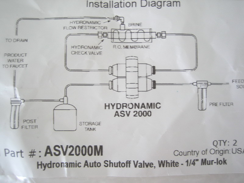
Flow diagram for 5 stage reverse osmosis water systems note. The auto shut off valve uses the back pressure amount created by the float valve. Automatic shut off valve aso diagram for reverse osmosis system shuts off waste water from exiting the ro system for a video on how to install this valve go to. The in out markings are on the top of the ...
Asv100 Hydronamic Auto Shutoff Valve White 1 8 Female Nptf 50 Gpd Or Less
Check Valve. The simplest DCV (Direction Control Valve ) is a check valve. A check valve allows flow in one direction, but blocks the flow in the opposite direction. It is a two-way valve because it contains two ports. Figure shows the graphical symbol of a check valve along with its no-flow and free-flow directions. Symbol Of Check Valve:

Advanced Water Systems Reverse Osmosis Water Filtration Water Filters And Water Softeners
7:43http://www.modularhydro.comThis video shows and explains how to install an automatic shut off valve on a ...4 Aug 2012 · Uploaded by ModularHydro

Buy Dmt Dmfit White Acetal Copolymer Valves Check Valve Push In Quick Inline 3 8 Od Inlet 3 8 Od Outlet Achv 0606 Nsf Ansi 61 372 Certificate For Reverse Osmosis Ro Water System
Fix-It-Yourself Reverse Osmosis Parts & Pieces List We stock a wide range of standard Reverse Osmosis parts and fittings. If you need help diagnosing an issue or selecting the correct replacement part please give us a call: (888) 382-3814. Note: For RO Membranes and Cartridges, go to our Cartridge Menu.
Free Shipping 50gpd Vontron Ro Membrane 1812 Ro Membrane Housing Reverse Osmosis Water Filter System Parts Parts Gateway Filter Vwparts Display Aliexpress
Check Valve (this is what I replaced): https://amzn.to/2OZDnwSAuto Shut Off Valve: https://amzn.to/33Ih7LSGE Reverse Osmosis System: https://amzn.to/31va0oNF...

Jual Promo Mesin Air Minum Reverse Osmosis Ro 50 Gpd Merk Micron Di Lapak Amanda Shop Bukalapak
See the below water flow diagram of an RO water purifier to understand the working of a flow restrictor. Flow Restrictor in RO Water Purifier. Flow restrictors are generally available in different flow ratings and must be properly sized according to the capacity of the RO membrane.

560043 Booster Pump Kit Premier
5:57This video will show you how to correctly install an Automatic Shutoff and Check Valve on a Reverse Osmosis ...18 Oct 2019 · Uploaded by LiquaGen
2
Understanding reverse osmosis valve functionality. Nov. 30, 2018. Each reverse osmosis valve is used to accurately and safely control the flow within various steps in a reverse osmosis system. Charles Kolstad. All graphics courtesy of Tameson. View Image Gallery.
Reverse Osmosis Installation Diagram
The Process Flow Diagram is a graphical representation used to demonstrate major components of a process in an Industrial plant or manufacturer, it is widely used in Chemical/petroleum or process engineering.. The Process flow diagrams are used to understand the process and its sequence, model a process, document a process, ensure quality control and standards plus increase efficiency.
Energies Free Full Text Dynamic Modeling And Preliminary Performance Analysis Of A New Solar Thermal Reverse Osmosis Desalination Process Html
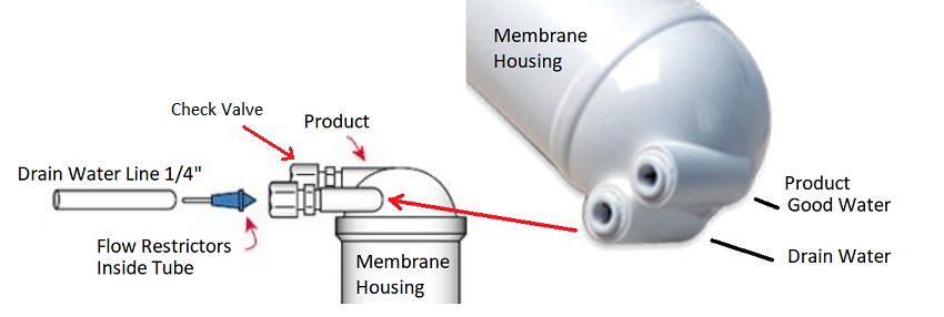
Reverse Osmosis Check Valves. Every reverse osmosis unit has a one-way valve called a check valve in the "permeate" line as it leaves the RO membrane housing. This is usually a small, inexpensive part, but it is essential to the function of the unit. Without a properly working check valve, the unit will not shut off properly when the tank ...
2
This procedure is intended to clean out your Reverse Osmosis System so the water you get will be pure and healthy. This process will take 12 hours. Please do not drink any water from your Reverse Osmosis Filter System until the System Start-Up has been completed. Allow pressure to build for 10 minutes. With the Reverse Osmosis Faucet
Faq Eagopure Ro Water Filter System
RO Check Valve Diagram RO Storage Tank Diagram RO Faucet Diagram Air Gap Faucet Diagram Non-Air Gap Faucet Diagram. Categories Reference Post navigation. Installing Reverse Osmosis System. Frizzlife SK99 Under Sink Water Filter. Leave a Comment Cancel reply. Comment. Name Email Website.
How Ro Shutoff Valves Work
1 121-1604-1 Check Valve Fitting 1/8" mpt x¼" JG Elbow 1 129-260 Flow Restrictor, 260 ml ... 02.21.17 12:22 PM Here is a manufacturers diagram for a Krystal Pure KR 10 reverse osmosis unit ... A man called in for a shut off valve for a Krystal Pure KR 10 reverse osmosis unit (manufactured by Ameriflow - also manufacturers of the ...

How To Install An Automatic Shut Of Valve On Your Reverse Osmosis System Youtube
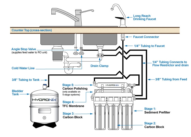
Reverse Osmosis System Components. RO Module The RO module is the main component and holds the pre-filters, membrane, and post-filter. A bracket is provided so they can be mounted under the sink or in a basement. Angle Stop Valve The angle stop valve connects to the cold water line to supply water to the RO system and provides an easy ability to shut off the water supply when servicing the unit.

How To Install An Automatic Shut Off Valve On A Reverse Osmosis System Youtube
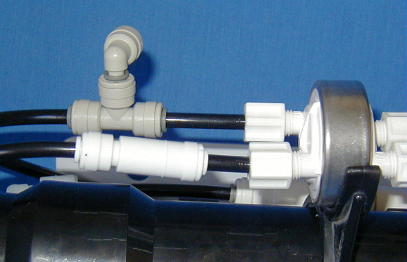
The blue line exits the RO membrane as filtered water, goes through the bottom of the valve to the DI resin or storage tank. The "in" and "out" portions are interchangeable for the blue line. To function properly the unit also requires a check valve on the filtered water end of the RO membrane. Many RO systems come with the check valve built in ...
About Reverse Osmosis Water Filtration Olympia Water Systems
To read and understand engineering fluid diagrams and prints, usually referred to as P&IDs, an individual must be familiar with the basic symbols. EO 1.1 IDENTIFY the symbols used on engineering P&IDs for the following types of valves: a. Globe valve g. Relief valve b. Gate valve h. Rupture disk c. Ball valve i. Three-way valve d. Check valve j.
Procedure Reverse Osmosis Debugging Gtawater Com
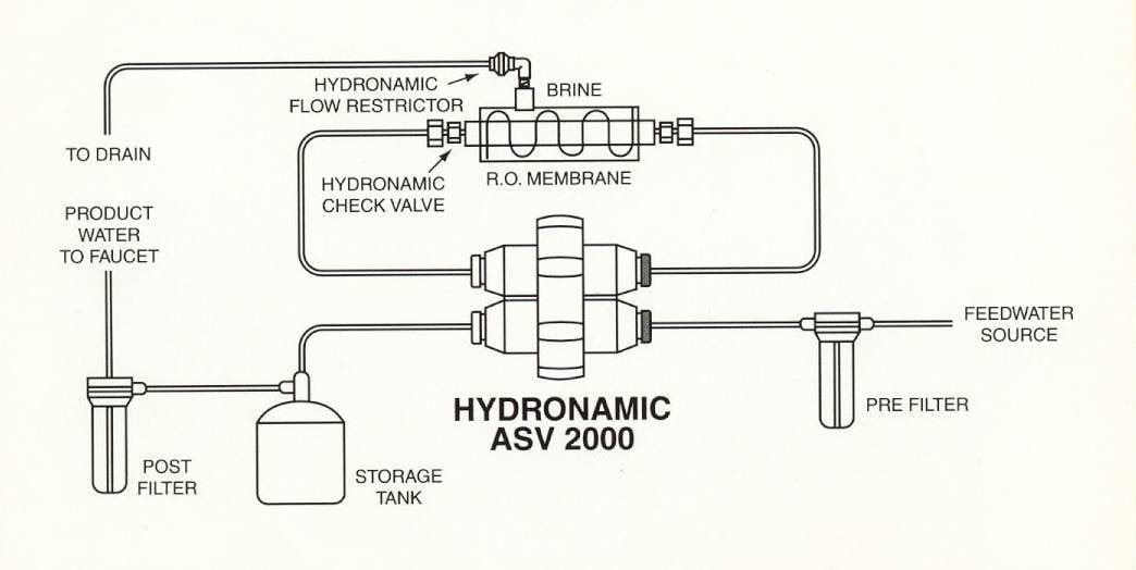
Automatic Shut Off Valve (ASO) Diagram For Reverse Osmosis System Shuts off waste water from exiting the RO system For a video on how to install this valve go to: modularhydro.com HIGH PRESSURE IN/OUT ASO OUT IN LOW PRESSURE IN OR OUT IN Out to RO membraneOUT RO Membrane Housing Out to waste Flow Restrictor Clean RO water Pre/Carbon Filters
Watts R 12 Reverse Osmosis Units Pure Water Products Llc
6. RO membrane damaged or clogged. 7. Product line crimped. 8. Post-filter clogged. 9. Ball valve on RO tank closed. 10. Check valve/restrictor valve clogged . Set tank pressure at 5-7 psi when empty. Check RO storage tank optimum pressure 5-7 psi when empty. Call for assistance – may require pressure pump. Turn water supply on

How To Install A Reverse Osmosis System Installation Diagram
*Reverse osmosis membranes have received FDA clearance for use in processing liquid foods and in purifying water for food applications. This clearance is published in the Code of Federal Regulations under Title 21, Section 177.2550, Reverse Osmosis Membranes. Our FT30 reverse osmosis membrane complies with this regulation.

Reverse Osmosis Repair Auto Shut Off Check Valve Water Filter Gxrm10g Ge Drain Running Youtube
http://www.modularhydro.comThis video explains the function of an automatic shut off valve (ASO) as well as how to assemble and disassemble or take apart the...
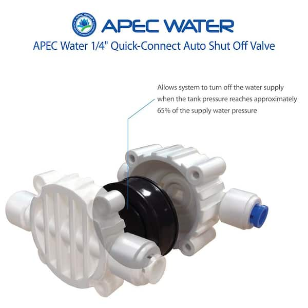
Apec Water Systems Auto Shut Off Valve With 1 4 In Quick Connect For Reverse Osmosis Water Filtration System Aso The Home Depot
Piloted check valves HGL Data sheet – Push-in connector Function-M-Flow rate 130 ... 1400 l/min-Q-Temperature range –10 ... +60°C-L-Operating pressure 0.05 ... 1 MPa The piloted check valve is suitable for brief positioning and braking functions in pneumatic drives. Compressed air flows to and from the drive as long as a control signal is

China Underground Water Filter System Manufacturers Suppliers Factory Direct Price Sokos Machinery
Check Valve - How They Work. Figure 1: Check valve. A check valve is a device that only allows the flow of fluids in one direction. They have two ports, one as an inlet for the media and one as the output for the media. Since they only allow media flow in one direction, they are commonly referred to as 'one way valves' or 'non return ...

Energy Recovery System In Small Reverse Osmosis Desalination Plant Experimental And Theoretical Investigations Sciencedirect
Replacement of the reverse osmosis component:This reverse osmosis system contains a replaceable component critical to the efficiency of the system. Replacement of the reverse osmosis component should be with one of identical specifications, as defined by the manufacturer, to assure the same efficiency and contaminant performance. 14"

Jenis Check Valve Cara Kerja Dan Fungsinya Project Team

Experimental Setup 1 Water Pumped From The Sump 2 Control Valve Download Scientific Diagram
Troubleshoot Info For Apec Reverse Osmosis Water Filters Systems
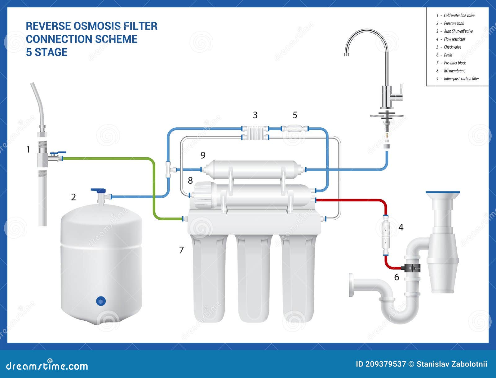
Connection Scheme Of The 5 Stage Reverse Osmosis Filter Stock Vector Illustration Of Line Postcarbon 209379537

8 Schematic Of The Semi Batch Ro System Used For Pilot Testing In Israel Download Scientific Diagram
Reverse Osmosis Check Valves Pure Water Products Llc
How Reverse Osmosis Water Purification Systems Work Ppt Download

Komponen Dasar Dari Sistem Reverse Osmosis
Schematics Of A High Pressure Water Switch Physics Forums

Pressure Exchanger Ksb

Help Instalasi Ro System
Under Counter Reverse Osmosis System East Coast Water Purification

Domestic Reverse Osmosis Troubleshooting Guide Osmotech Pty Ltd

Check Valve With Plastic Locking Element
Autotopoff Com

How To Troubleshoot Your Reverse Osmosis System Fresh Water Systems
How Ro Shutoff Valves Work
0 Response to "40 ro check valve diagram"
Post a Comment