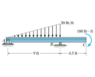
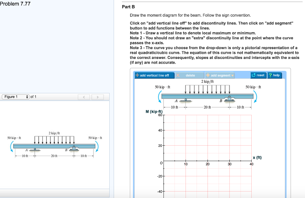
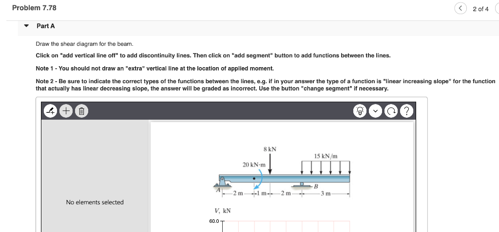
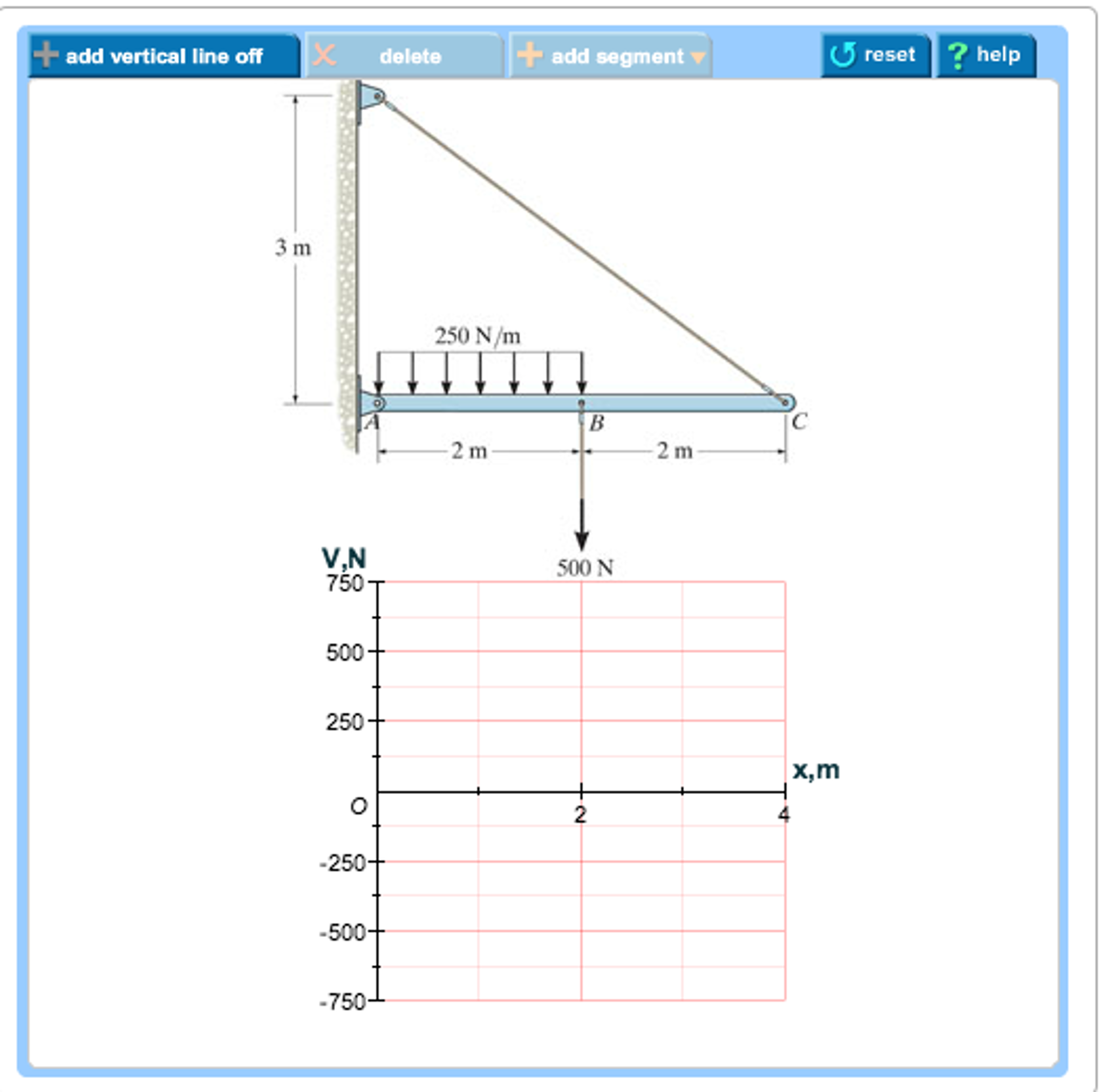
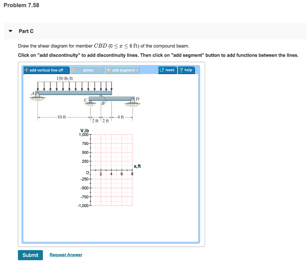
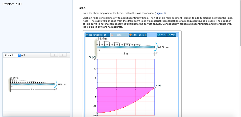
42 problem 7.78 part a draw the shear diagram for the beam.
2.4 Free Body Diagrams Free Body Diagram is very crucial for all numerical problems as it represents the skeleton of the force system which can be analyzed easily by using law of forces. Following are the steps required to draw the free body diagram of a body: i. ii. iii. iv. Draw the figure of the body separately, i.e., draw the isolated body. Apr 03, 2020 · As we know beam is simply supported at both end and it will not resist the bending moment at the supports that is why, ∑M a = ∑M b= 0. Correct problem 753 part a draw the shear diagram for the beam. 79 (Text book – page: 359) The beam consists of …
Nov 03, 2021 · Draw the shear diagram under the free-body-diagram. F and B. 8 KN 2. 8 x 76. •7–81. Jan 12, 2018 · Solved problem 7 80 part a draw the shear diagram for solved f6 12 draw the shear and moment diagrams for. 00 In a simply supported beam, the shear force should be zero at the point of maximum moment.

Problem 7.78 part a draw the shear diagram for the beam.
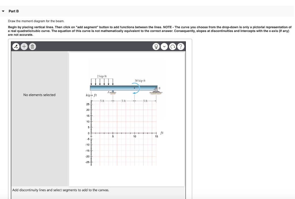
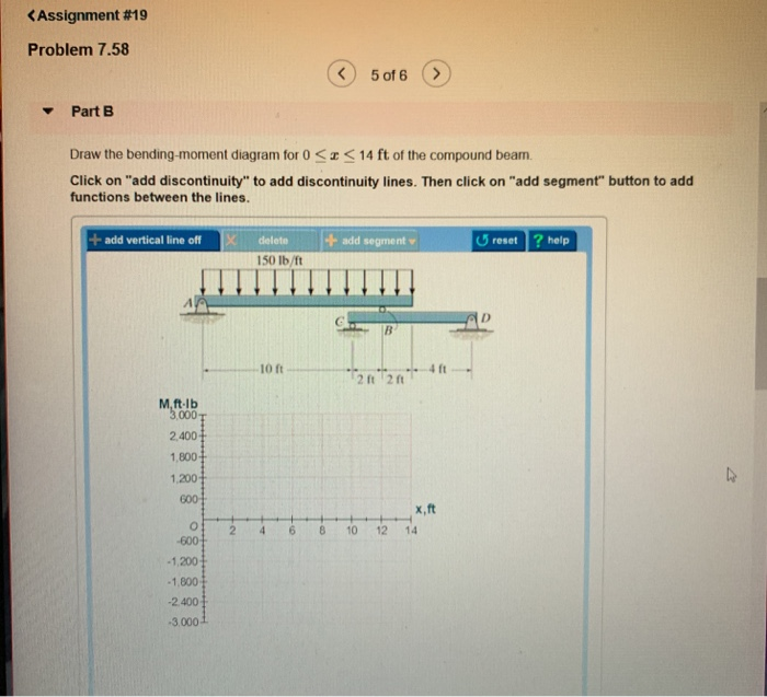
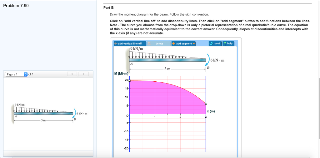
problem 7.80 part A draw the shear diagram for the beam. part B draw the moment diagram for the beam; Question: problem 7.80 part A draw the shear diagram for the beam. part B draw the moment diagram for the beam Question: problem 7.78 Part A Draw the shear diagram for the beam. Click on "add vertical line off" to add discontinuity lines. Then click on "add segment" button to add functions between the lines. Note 1 - You should not draw an "extra" vertical line at the location of applied moment. examples and problems in mechanics of materials stress-strain state at a point of elastic deformable solid editor-in-chief yakiv karpov
Problem 7.78 part a draw the shear diagram for the beam.. Solution Manual - Mechanics Of Materials 7th Edition, Gere, Goodno - ID:5c18dde35afdf. 00FM.qxd 9/29/08 8:49 PM Page i An Instructor’s Solutions Manual to Accompany ISBN-13: 978-0-495-24458-5 ISBN-10: 0-495-... Textbook solution for INTERNATIONAL EDITION---Engineering Mechanics:… 14th Edition Russell C. Hibbeler Chapter 7.3 Problem 78P. We have step-by-step solutions for your textbooks written by Bartleby experts! Question: 7-78. Draw the shear and moment diagrams for the beam. I attached the Prob. 7-78 as a picture shown. This problem has been solved! See the answer See the answer See the answer done loading. 7-78. Draw the shear and moment diagrams for the beam. I attached the Prob. 7-78 as a picture shown. Problem 778 part a draw the shear diagram for the beam. Correct problem 753 part a draw the shear diagram for the beam. Draw the shear and moment diagrams for the shaft. Your shear diagram is correct. No part of this manual may be displayed reproduced or distributed in any form or by any means without the prior written permission of the ...
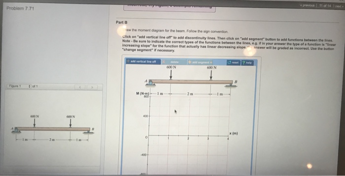
Answer to problem 780 part a draw the shear diagram for the beam. I attached the prob. Shear force and bending moment diagram practice problem 1 duration. 7 78 as a picture shown. Draw the shear and moment diagrams for the shaft. I attached the prob. Correct problem 753 part a draw the shear diagram for the beam. See the answer. Problem 7.78. Part A. Draw the shear diagram for the beam. Click on "add vertical line off" to add discontinuity lines. Then click on "add segment" button to add functions between the lines. Be sure to indicate the correct types of the functions between the lines, e.g. if in your answer the type of a function is "linear ... Problem 7.78 part a draw the shear diagram for the beam.. Answer to problem 780 part a draw the shear diagram for the beam. 7 78 as a picture shown. Shear force and bending moment diagram practice problem 1 duration. Draw the shear and moment diagrams for the beam. Click on add discontinuity to add discontinuity lines. 7.78 Draw the shear and moment diagram for the beam. Question: 7.78 Draw the shear and moment diagram for the beam. This problem has been solved! See the answer See the answer See the answer done loading. 7.78 Draw the shear and moment diagram for the beam. Videos. Step-by-step answer.
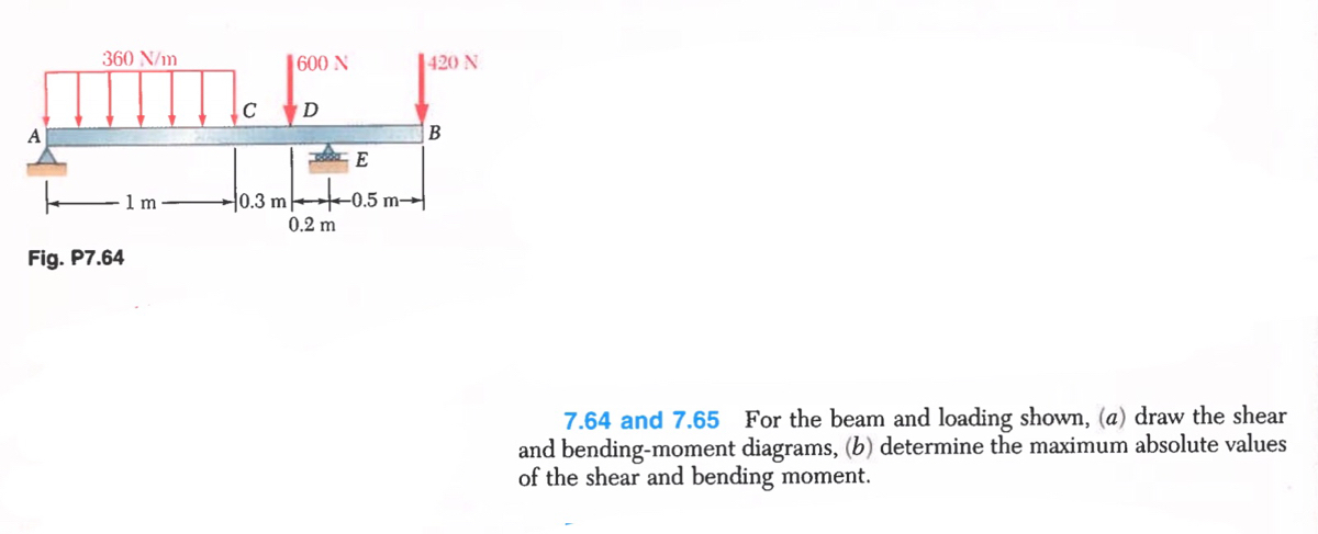
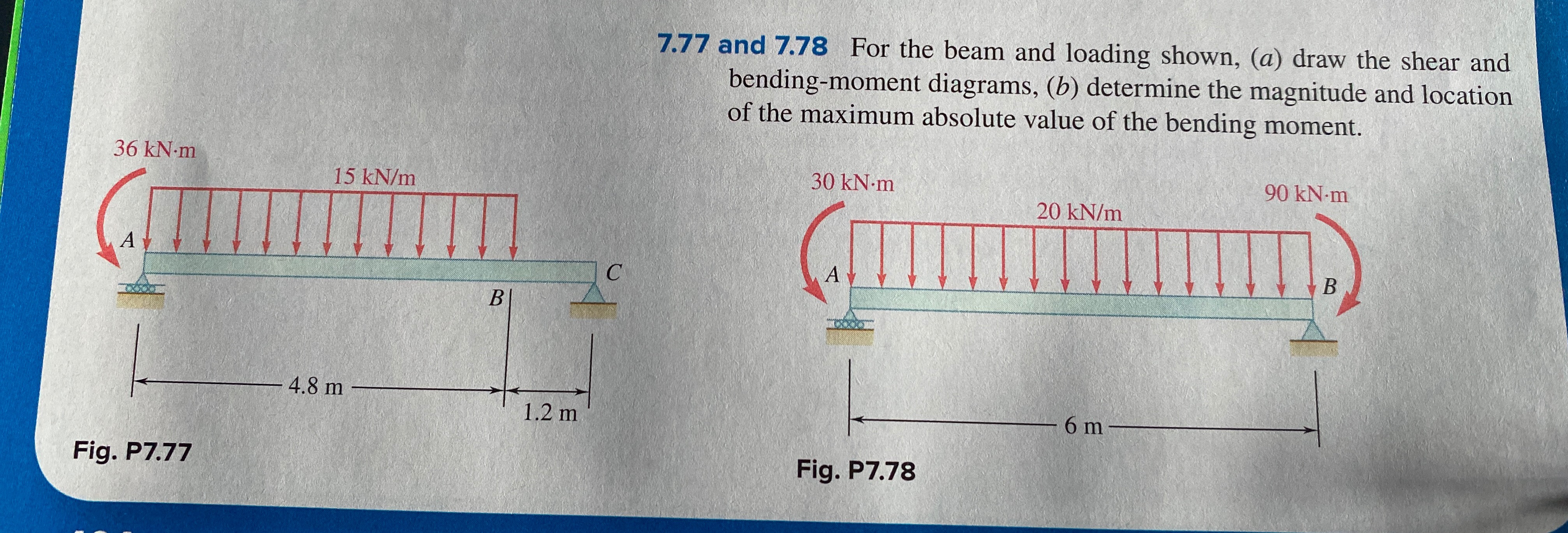
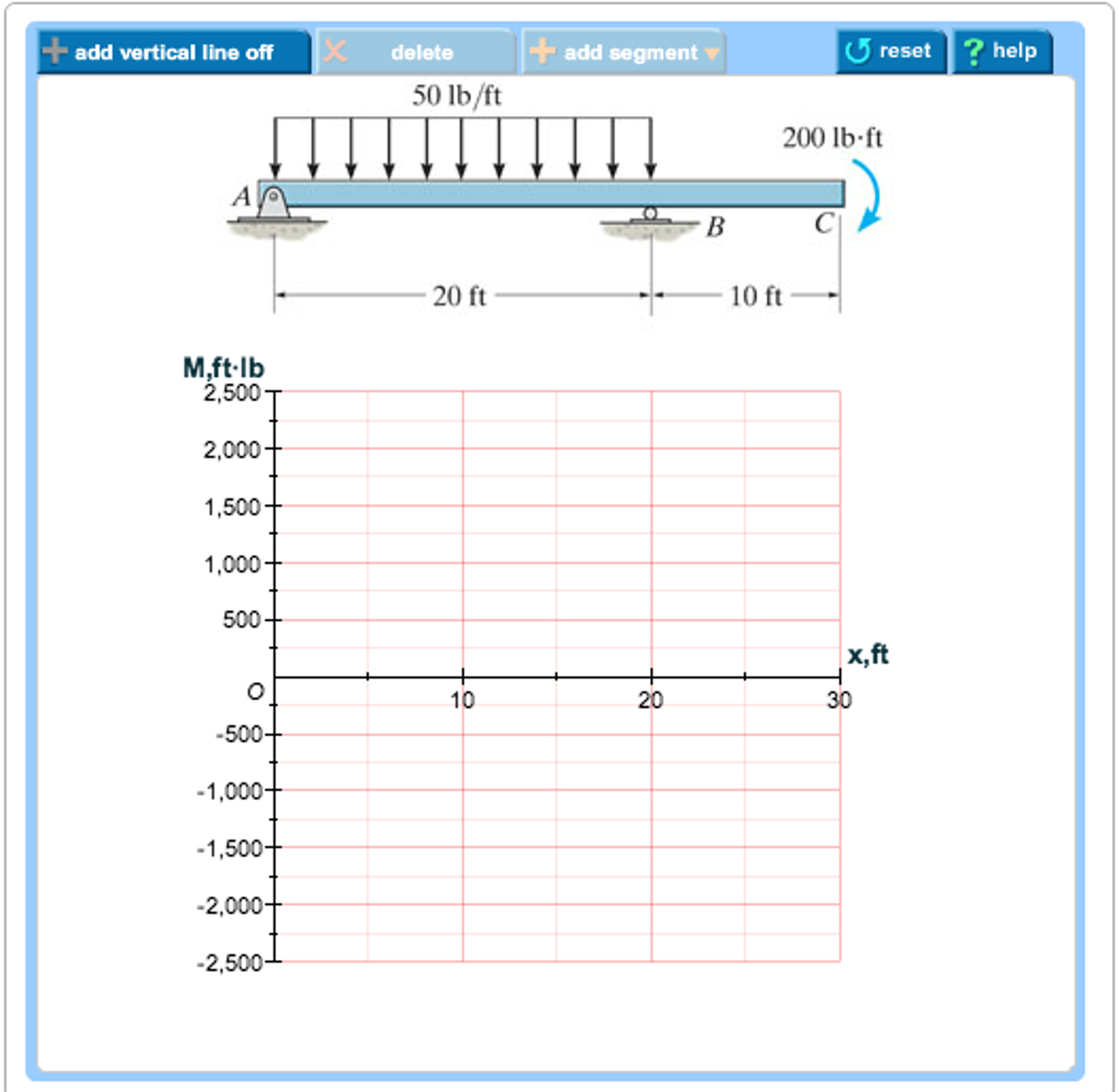
Fluid Mechanics Frank White 5th Ed - ID:5c142a11d322e. Fluid Mechanics McGraw-Hill Series in Mechanical Engineering CONSULTING EDITORS Jack P. Holman, Southern Methodist Univ... This part of the course will apply the sightline control (SLC) fundamentals described in Part 1.0 to the geo-pointing and location problem. Initially Section 1.0 Part 1.0 is reviewed, particularly pointing performance requirements which directly impact geo-pointing and location performance. Mechanical Engineering Q&;A Library 7.77 and 7.78 For the beam and loading shown, (a) draw the shear and bending-moment diagrams, (b) determine the magnitude and location of the maximum absolute value of the bending moment. Homework Problems. Apart from the Fundamental and Conceptual type problems mentioned previously, other types of problems contained in the book include the following: • Free-Body Diagram Problems. Some sections of the book contain introductory problems that only require drawing the free-body diagram for the specific problems within a problem set.
draw free-body diagrams of bolt HJ and of the portion of the bolt located between the two planes (Fig. 1.19). Observing that the shear P in each of the sections is P = F∕2, the average shearing stress is τave = P F∕2 F = = A A 2A (1.10) H FC F K P K' L F L' P FD J (a) (b) …
Academia.edu is a platform for academics to share research papers.
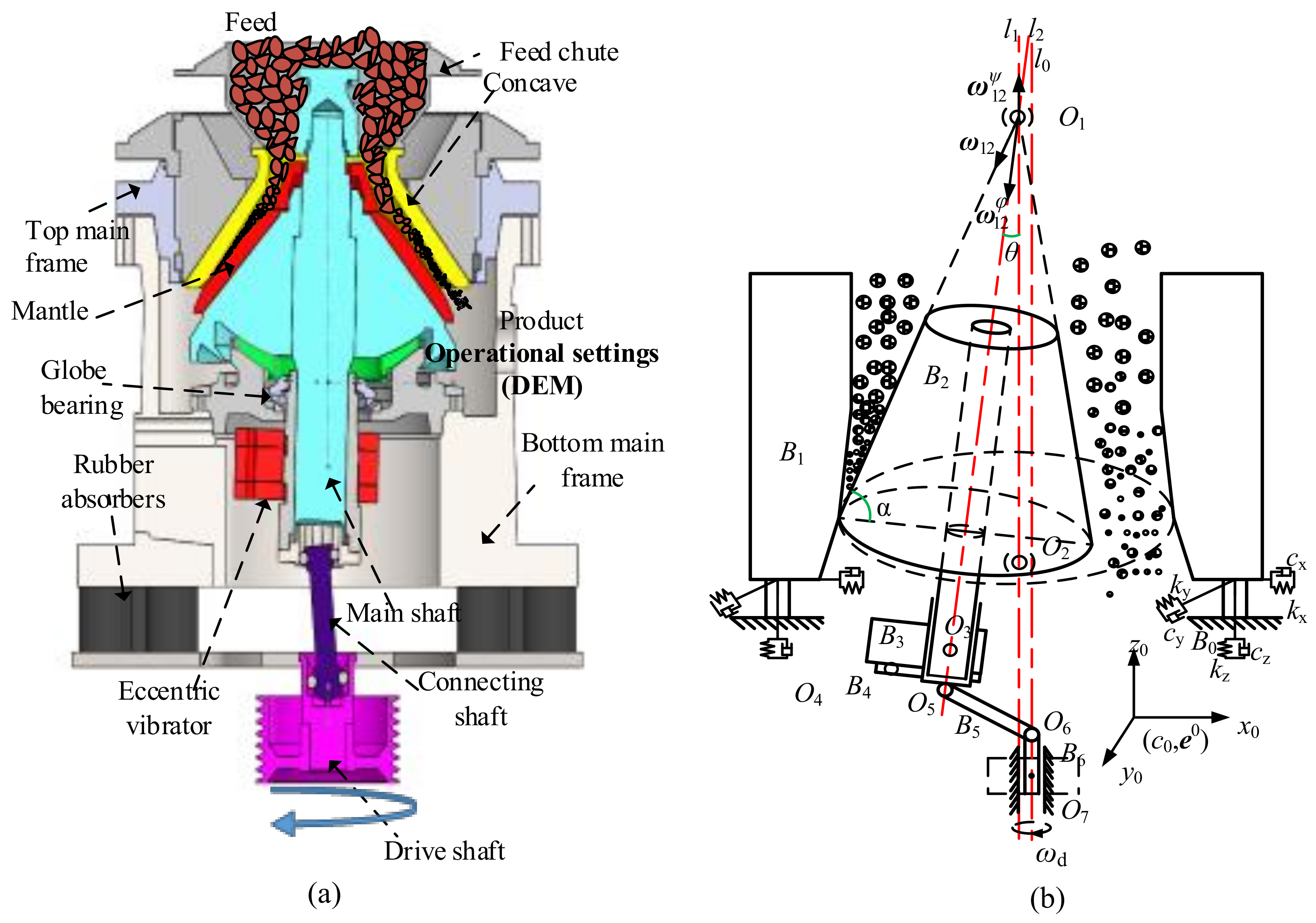
Minerals Free Full Text Influence Of Two Mass Variables On Inertia Cone Crusher Performance And Optimization Of Dynamic Balance Html
examples and problems in mechanics of materials stress-strain state at a point of elastic deformable solid editor-in-chief yakiv karpov

Mastering Engineering Assignment 12 Beams Engineering Mechanics Statics Assignment12beams Due 11 59pmontuesday April26 2016 Gradingpolicy Course Hero
Question: problem 7.78 Part A Draw the shear diagram for the beam. Click on "add vertical line off" to add discontinuity lines. Then click on "add segment" button to add functions between the lines. Note 1 - You should not draw an "extra" vertical line at the location of applied moment.
problem 7.80 part A draw the shear diagram for the beam. part B draw the moment diagram for the beam; Question: problem 7.80 part A draw the shear diagram for the beam. part B draw the moment diagram for the beam
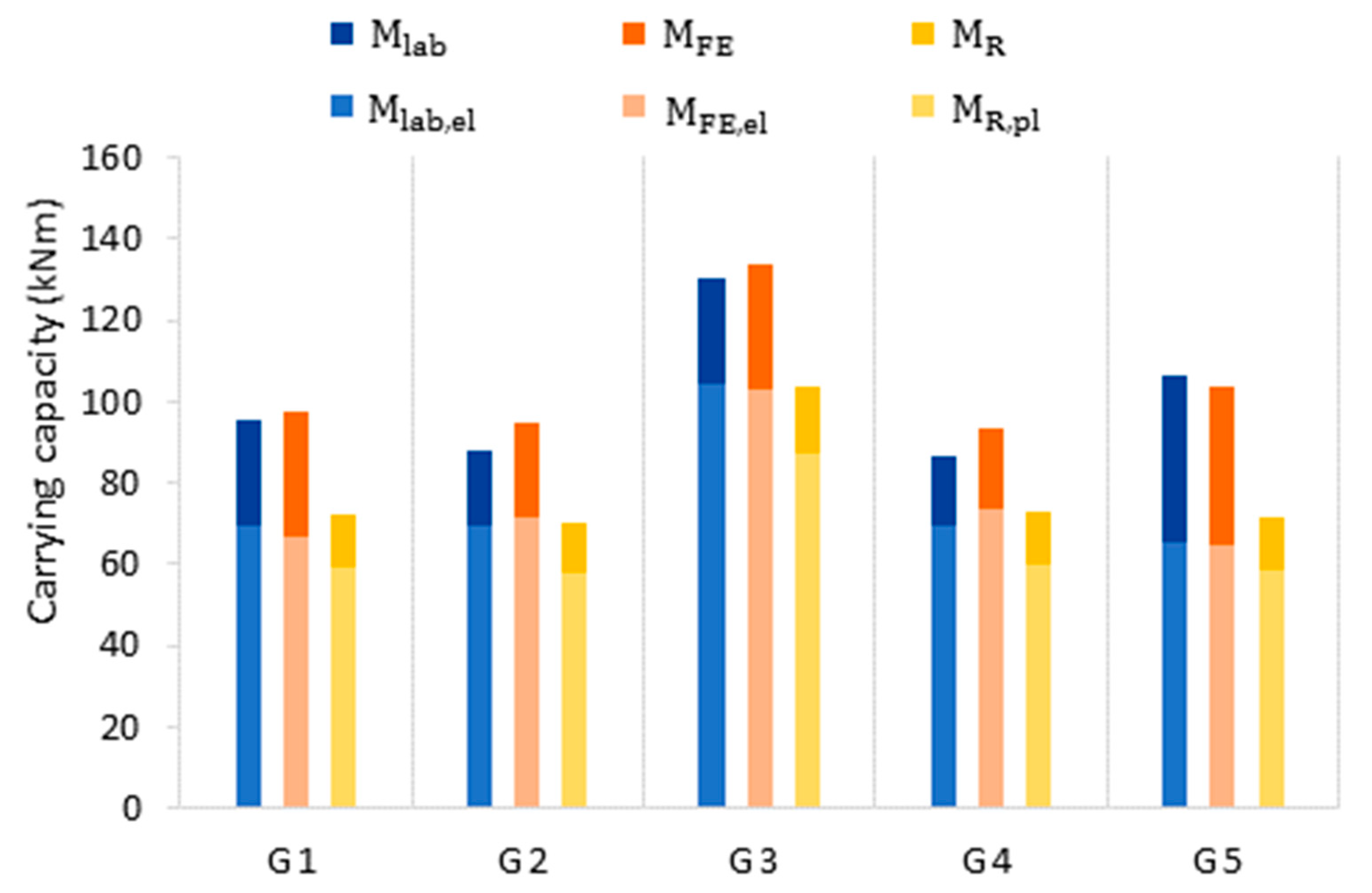
Materials Free Full Text Assessment Of The Bending Moment Capacity Of Naturally Corroded Box Section Beams Html
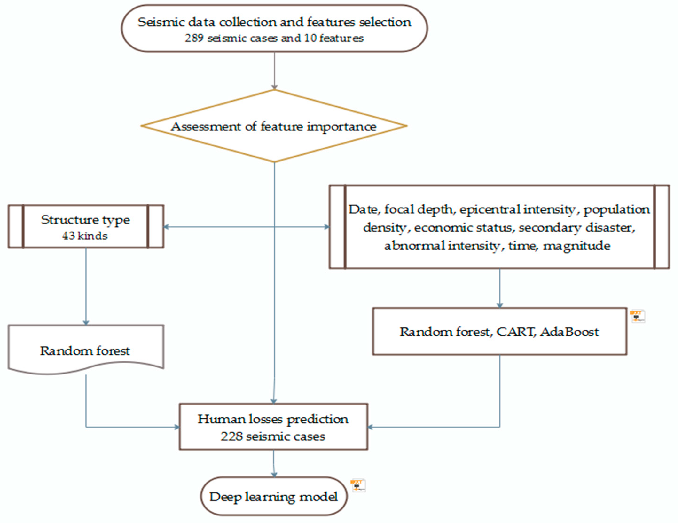
Sustainability Free Full Text An Earthquake Fatalities Assessment Method Based On Feature Importance With Deep Learning And Random Forest Models Html

Problem 1 Using Graphical Method Draw The Shear And Bending Moment Diagrams For The Beam Shown In The Figure Determine The Absolute Maximum Bending Ppt Video Online Download
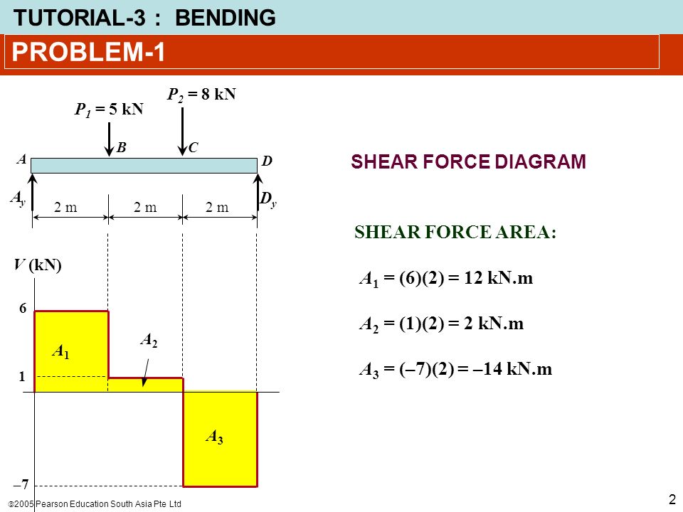
Problem 1 Using Graphical Method Draw The Shear And Bending Moment Diagrams For The Beam Shown In The Figure Determine The Absolute Maximum Bending Ppt Video Online Download

C Mcgraw Hill Education All Rights Reserved No Reproduction Or Distribution Without The Prior Written Consent Of Mcgraw Hill Education Pdf Geometry Space

On The Effect Of Seismic Base Isolation On Seismic Design Requirements Of Rc Structures Sciencedirect

A Calculate The Reactions At Support A And B B Draw The Shear Force Diagrams Label All Significant Value C Draw The Bending Moment Diagrams Label All Significant Value What

Problem 3 For The Following Stress State Draw A Mohr S Circle Diagram Find The Principal Stresses Homeworklib

Mastering Engineering Assignment 12 Beams Engineering Mechanics Statics Assignment12beams Due 11 59pmontuesday April26 2016 Gradingpolicy Course Hero








0 Response to "42 problem 7.78 part a draw the shear diagram for the beam."
Post a Comment