37 alternator exciter wiring diagram
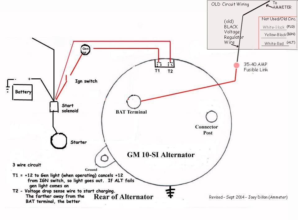
You connect the output of the alternator back to this terminal so that it can sense and regulate the output voltage. The other terminal is the exciter. This is what excites the field of the alternator. The following diagram shows the wiring for a typical 3-wire alternator connected to our Infinitybox system.
According to earlier, the lines at a Alternator Exciter Wiring Diagram signifies wires. Sometimes, the wires will cross. But, it does not mean connection between the wires. Injunction of two wires is usually indicated by black dot on the intersection of two lines. There'll be primary lines which are represented by L1, L2, L3, and so on.
visit: http://www.alternatorparts.com
Alternator exciter wiring diagram
Microcontroller - How To Monitor An Alternator Exciter Wire With Mcu - Alternator Exciter Wiring Diagram Wiring Diagram contains numerous in depth illustrations that present the connection of assorted items. It consists of guidelines and diagrams for different varieties of wiring methods and other items like lights, home windows, and so forth.
Ok, interesting turn of events. The main red wire on the alternator harness/plug has power both on and off. The exciter wire had zero volts off, and only 0.8 volts on. I then checked the voltage at each of the wires coming from the idiot light.
This is a three-wire alternating wiring diagram showing the connections between the different components of a circuit. The circuit comprises three main wires: battery positive cable, voltage sensing wire, and ignition wire. The ignition input wire is attached to the engine.
Alternator exciter wiring diagram.
The exciter rotor AC output is rectified to a DC input for the main generator rotor. More advanced systems use an additional input to the AVR. This article will explore the construction, function and application for each method and includes diagrams and illustrations for each. Automatic Voltage Regulator (AVR)
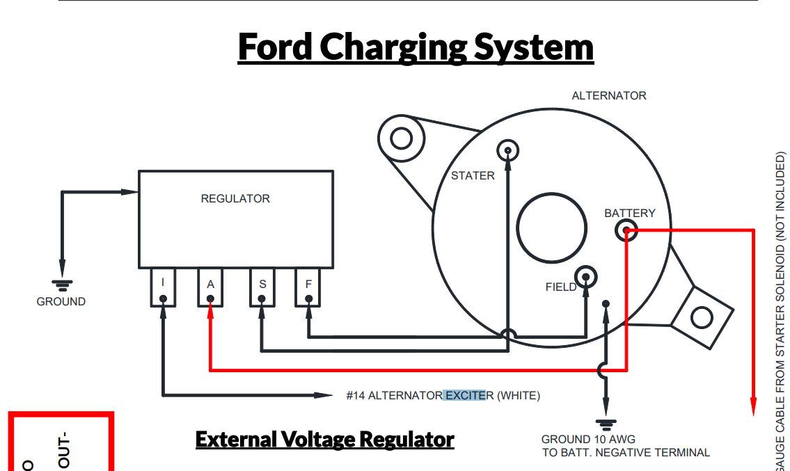
Alternator Exciter Wiring Diagram loop the red wire off the plug to the post on the rear of the alternator . And if there isn't one, I connect the exciter wire to the ignition circuit, thru. White wire says "to alternator regulator exciter". It looks like you are using the wiring diagram for a internal regulator alternator but using a.
Tractor Alternator Wiring Diagram Simple Alternator Exciter Wiring - Simple Alternator Wiring Diagram. The diagram provides visual representation of an electrical arrangement. However, this diagram is a simplified version of this structure. It makes the process of building circuit easier.
Ford Alternator Wiring Diagram This is the diagram of every components in the alternator. It is a diagram for the alternator in a Ford Focus (see also Ford Focus Repair Manual ), Ford Escort, Ford F-100, Ford Taurus, Ford Mustang, Ford Model T, Ford GT40, Ford Thunderbird, Ford Shelby Cobra and other Ford cars that use the similar alternator.
The sense wire, what you are calling the exciter wire should not be going through the alternator light. It should be tied to a switched source somewhere near the fuse block. A 10 or 12 SI have 3 connections, the large stud is for the battery feed, The number 1 small terminal is for the light wire the number 2 terminal is for the Sense wire.
From what I can figure looking at a VW wiring diagram, the D+ prong is for the exciter/ammeter. ... This type alternator does not need a exciter wire. Only two for the battery (heavy gauge) and one for a light if you want it. My alternator has the suppression device on the + terminal like in the second picture.
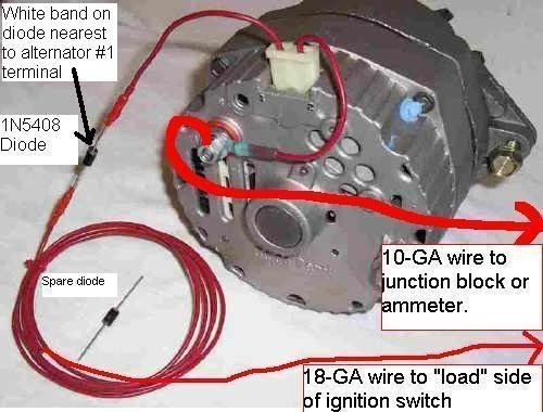
Each kit comes with a mounting bracket, tightener bracket, correct size pulley, diode/exciter wire, and wiring instructions and wiring diagrams. 10SI Alternator Wiring. The 10SI has three terminals (including those with a 1 wire regulator). The large "BATT" terminal which gets connected to your battery positive.
92 Volvo 240 Alternator Wiring Diagram. 1987 240 alternator not charging exciter wire volvo forums enthusiasts forum page wiring issues turbobricks installation and cer lamp idiot light i have a 1990 dl with an electrical problem cannot solve the battery does charge when car is running at dave s adjule voltage regulators 93 ground in wrong ...
As per the original Universal wiring diagram, I do not see a wire connected to the exciter terminal on the alternator, but only a purple wire to the sensing terminal. However, as per the Mando alternator wiring diagram, there is a wire on both the exciter terminal and the sensing terminal.
Alternator Testing You should have a reading of approximately14.5 to 14.9 vdc. If not, unplug the exciter wire and verify you have 12 vdc at the wire plug. If good, remove the plug from the exciter wire and plug it directly to the alternator "L" terminal. If now good, replace the exciter wire pigtail.
Dirty dingo motorsports pages ls conversion swap information c5 ls1 alternator wiring question ls1tech camaro and firebird forum discussion cobra club forums how to make the 1 wire chevy page engines drivetrain pistonheads uk serpentine 2005 gto ls2 pictures included v8 miata home of diagram reference 1947 present chevrolet gmc truck message board network new engine chassis corvetteforum ...
Charge wire connects from the alternator to the battery through the . the resistor or directly to the key switch itself (switched side). This wiring configuration will excite the alternator to start charging when the engine is running at low RPM's. ... alt-wire-diagram Author: jay johnson
Basic wiring diagram to replace the alternator and the exciter wire pigtail. The power wire attaches to the battery like you have it. Plug the alternator connector in the receptacle on the alternator. Disconnect the battery negative terminal. How to Wire an AC Delco 3 Wire Alternator. Free sexting watsontown Let me tell the job interview.
Not knowing how your boat was originally wired, I'd try to find a wiring diagram from a sistership to see how that particular alternator was supposed to be installed. Or, contact the alternator maker and ask them--they're usually pretty good about it--how that exciter wire was supposed to be connected.
Microcontroller - How To Monitor An Alternator Exciter Wire With Mcu - Alternator Exciter Wiring Diagram Wiring Diagram contains numerous in depth illustrations that present the connection of assorted items. It consists of guidelines and diagrams for different varieties of wiring methods and other items like lights, home windows, and so forth.
Generator Exciter Wiring Diagram. 2 circuit diagram of the exciter and generator excitation control systems system for alternator basic a three phase star shunt or self excited automatic voltage regulator avr field cat pdf figure 4 10 brushless schematic what is pmg on. Generator Excitation Control Systems Methods Shunt Ebs Pmg And Aux W Diagrams.
To Battery. Alternator. Basic wiring diagram to , replace the alternator and the exciter wire pigtail. However, as per the Mando alternator wiring diagram, there is a wire on both the exciter terminal and the sensing terminal. After the engine.May 01, · With the engine running at idle, my alternator is putting out 14 or so volts.
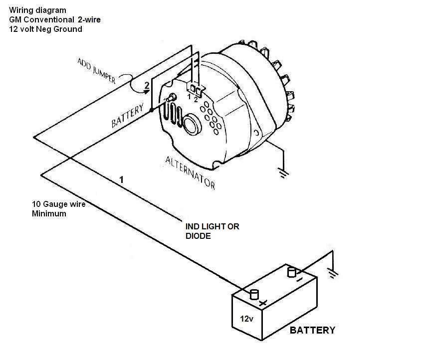
2wire gm alternator wiring diagram 2 wire gm alternator wiring inside 1 wire alternator wiring diagram image size 800 x 600 px image source. Turn switch electric fan horn battery feed alternator and alternator exciter wire coil and air conditioning. It is intended to aid each of the average consumer in creating a proper method.
I wired the alternator according to the manufacturer's spec (POS, NEG, EXC to key on power source). I wired the ignition light (supplied with a switch panel that was purchased for this boat) into the alternator EXC wire in this fashion: Key-on power to the + side of the light, and the - side of the light to the EXC post on the alternator.
Self-Exciting Alternator makes no need for Alternator Wiring Diagram The Self-Exciting alternator is an alternator that has a special voltage regulator that doesn't need an ignition wire to activate it.This is usually based on a chevy alternator type and only requires a battery wire connected to the battery terminal.
The diagram is here. ... Connecting the exciter wire straight to the charging wire in short makes it like the old self exciter alts. But I've always wondered if leaving it like that would cause the alt's exciter to eventually drain the battery with engine off. ... Connecting the exciter or sense wire will cause the alternator to drain the ...
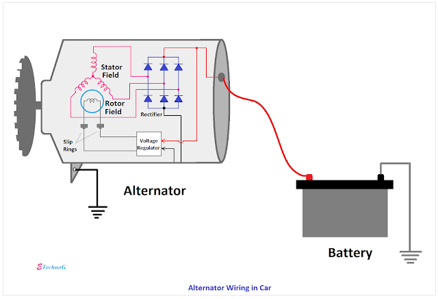
Exciter In the following diagram, the exciter is correctly depicted as a rotating electrical assembly, located within the alternator, with the exciter armature attached to the alternator shaft. The exciter rotor is located adjacent to the main rotor and is electrically separated by the rotating rectifier unit.
Exciting a car alternator requires 13.8 volts DC for a maximum voltage of 12v ignition system. The maximum output of your alternator ranges between 14.1- and 14.4-volts DC after regulation. The voltage regulator supplies power to the battery when it's at the nominal level. So, a charged battery will measure over 14 volts and stay steady.








0 Response to "37 alternator exciter wiring diagram"
Post a Comment