37 iron-iron carbide phase diagram
2) Cementite : Iron carbide(Fe 3 C), contains 6.67% wt. C Orthorhombic structure, HARD and BRITTLE 3) Pearlite : Phase mixture (ferrite+cementite), Lamellar structure, contains ~0.8% wt. C Produced from austenite decomposition 4) Austenite : o g-iron, Solid solution, stable at higher temperatures (>727 C) o Max.
The Iron-Carbon Phase Diagram The phase diagrams are very important tools in the study of alloys for solutions of many practical problems in metallurgy. These diagrams define the regions of the stability of a phase which can exist in an alloy system under the condition of constant atmospheric pressure.
In fact, the compound iron carbide decomposes into iron and carbon (graphite). Which phase is not present in iron carbon phase diagram? The phase diagram has all three phases ferrite, pearlite, cementite but not martensite. What is Fe fe3c diagram? The Fe-C phase diagram is a fairly complex one, but we will only consider the steel part of the ...
Iron-iron carbide phase diagram
The main evolution stages of the phase diagram of Fe-C in the carbide region (on the right from the cementite line) is a recently discussed theoretical topic that has been considered. It has been determined that previously isolated ε-Fe 2 C, χ-Fe 5 C 2, and g-Fe 7 C 3 carbides (except for cementite Θ-Fe 3 C) are nonstoichiometric compounds.
Iron carbide (Fe 3 C) is often labeled as the uncorroded portion of the steel. It is primarily associated with mild steels having a high carbon content and a ferritic-pearlitic microstructure. During corrosion of such steel, the ferrite phase dissolves and a porous iron carbide network is exposed (see Fig. 7.6).Given that iron carbide is an electronic conductor, this porous network serves as ...
Phase Diagrams (Iron-Iron Carbide Phase Diagram) Prof. Ratna Kumar Annabattula Department of Mechanical Engineering IIT MadrasSolid State Transofrmations, A...
Iron-iron carbide phase diagram.
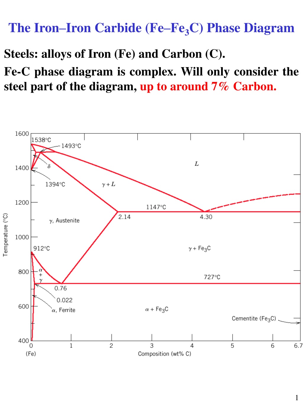
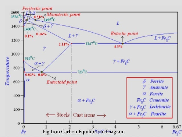
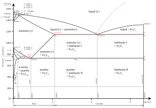
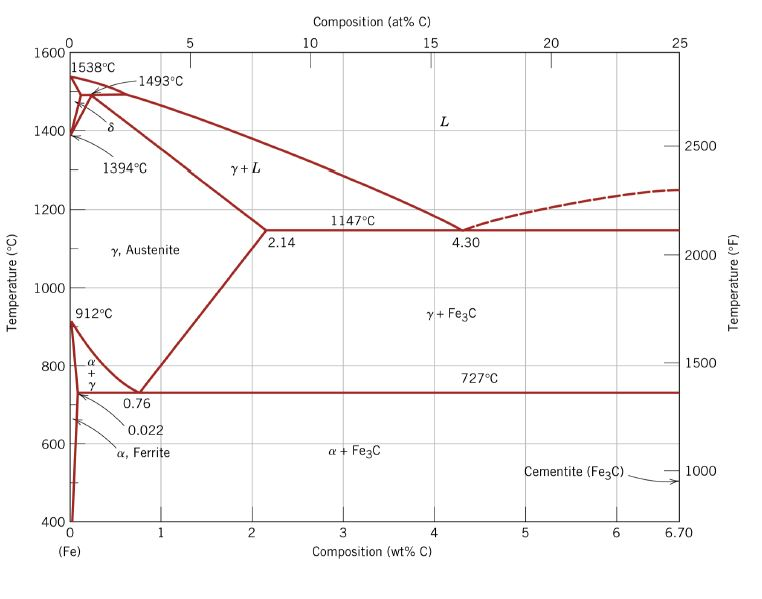
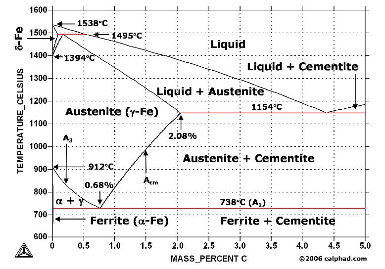
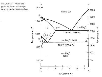
The Iron ‐Iron Carbide (Fe‐Fe 3 C) Phase Diagram PeritecticL+ δ = γ at T=1493oC and 0.18wt%C Eutectic L = γ +Fe 3 C at T=1147oC and 4.3wt%C Eutectoid γ = α +Fe 3 C at T=727oC and 0.77wt%C Phases Present L Reactions
So let's start with a phase diagram that contains maximal information: A 1: The upper limit of the ferrite / cementite phase field (horizontal line going through the eutectoid point). A2: The temperature where iron looses its magnetism (so-called Curie temperature ). Note that for pure iron this is still in the α -phase.
Important phases in Iron Iron Carbide Phase diagram has discussed in this video. Please subscribe to this our channel for more videos. #metallurgy #metallurg...
for example: the A1 point would be reduced from 723°C to 690 °C.The iron‒iron carbide (Fe‒Fe 3 C) phase diagram. The percentage of carbon present and the temperature define Page 1/5. Read Book Iron Carbon Phase Diagram A Review See Callister Chapter 9
English: Iron-carbon phase diagram under atmospheric pressure. This diagram is limited by pure iron on the left and by iron carbide on the right. The mains phases are: * iron: ferrite, ferritic steel * iron: austenite, austenitic steel * iron carbide: cementite, Fe3C. We can see a eutectic and a eutectoid; these phases crystallise as a stacking ...
The iron-carbon diagram (also called the iron-carbon phase or equilibrium diagram) is a graphic representation of the respective microstructure states depending on temperature (y axis) and carbon content (x axis). The melt essentially cools via the austenite to ferrite phases - i.e. from gamma to alpha mixed crystal.
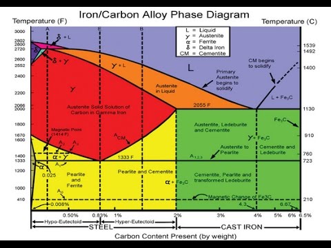
The weight percentage scale on the X-axis of the iron carbon phase diagram goes from 0% up to 6.67% Carbon. Up to a maximum carbon content of 0.008% weight of Carbon, the metal is simply called iron or pure iron. It exists in the α-ferrite form at room temperature. From 0.008% up to 2.14% carbon content, the iron carbon alloy is called steel.
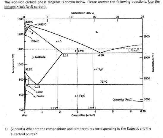
Example: Phase Equilibria For a 99.6 wt% Fe-0.40 wt% C at a temperature just below the eutectoid, determine the following a) composition of Fe 3C and ferrite (α) b) the amount of carbide (cementite) in grams that forms per 100 g of steel c) the amount of pearlite and proeutectoid ferrite (α)
C Phase Diagram. ➢ α-ferrite - solid solution of C in BCC Fe. • Stable form of iron at room temperature. • Transforms to FCC g-austenite at 912 °C.67 pages
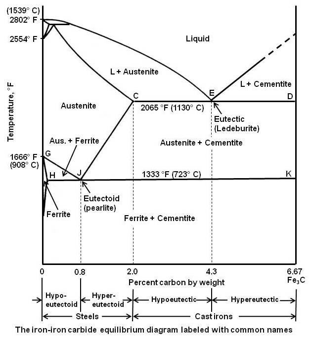
The Iron-Carbon Diagram: A map of the temperature at which different phase changes occur on very slow heating and cooling in relation to Carbon, is called Iron- Carbon Diagram. Iron- Carbon diagram shows - the type of alloys formed under very slow cooling, proper heat-treatment temperature and
Iron carbon phase diagram austenite This is also known as γFe. When we heat this solution, it converts into ferrite at a temperature above 2543°F. Austenite is usually unstable at temperatures below 727°C. This phase is non-magnetic in nature, and it changes rapidly.
The Iron-Iron Carbide Diagram • A map of the temperature at which different phase changes occur on very slow heating and cooling in relation to Carbon, is called Iron- Carbon Diagram. • Iron- Carbon diagram shows - The type of alloys formed under very slow cooling, - Proper heat-treatment temperature and
Ppt - the iron–iron carbide (fe–fe 3 c) phase diagram powerpoint ...
The iron-iron carbide phase diagram is shown in the Animated Figure 9.24. Question: Compute (a) the mass fractions of proeutectoid ferrite and (b) the mass fraction of pearlite that form in an iron-carbon alloy containing 0.30 wt% C. The iron-iron carbide phase diagram is shown in the Animated Figure 9.24.

The iron - iron carbide (fe-fe c) phase diagram
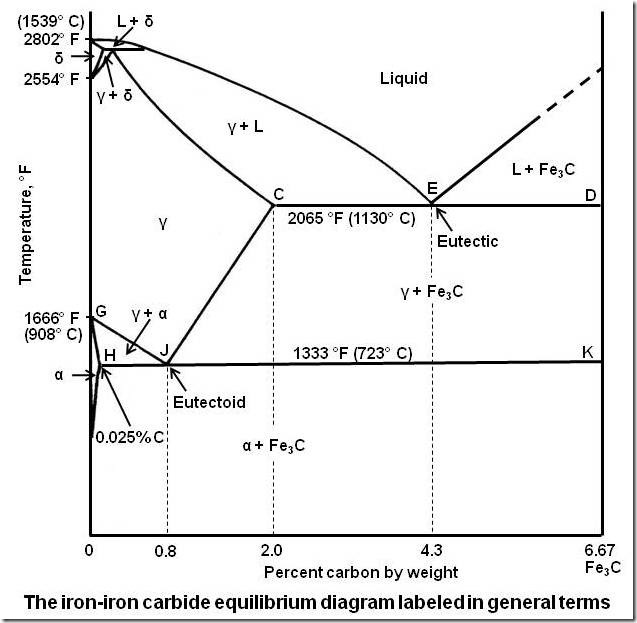
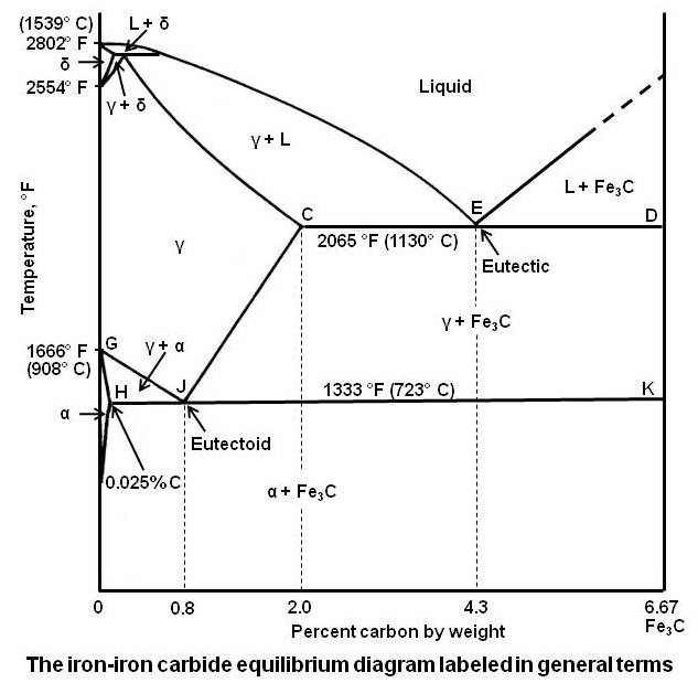
The Iron-Iron Carbide Diagram The part of iron-carbon alloy system diagram between pure iron and an interstitial compound, iron carbide (Fe 3 C), containing 6.67 percent carbon by weight is called iron-iron carbide equilibrium diagram.

7 iron carbon phase ideas | carbon, iron, mechanical engineering
Dr. Dmitri Kopeliovich Iron-carbon phase diagram describes the iron-carbon system of alloys containing up to 6.67% of carbon, discloses the phases compositions and their transformations occurring with the alloys during their cooling or heating.. Carbon content 6.67% corresponds to the fixed composition of the iron carbide Fe 3 C. . The diagram is presented in the picture:
Practical maintenance » blog archive » the iron-iron carbide ...
Iron can exist in more than one crystalline form, so an engineer should know at what temperature and composition, which phase exist? What will be the properties? All the important concepts of Iron Iron Carbide phase diagram are explained. Phases like, Ferrite, Austenite, Cementite are explained in details.
Coloring vector ironcarbon phase diagram stock vector (royalty ...
The iron-iron carbide (Fe-Fe3C) phase diagram Microstructures of iron α- ferrite austenite. 2 Interstitial sites of FCC Interstitial sites of BCC. 3 Microstructure in iron-carbon alloys REutectic--pearlite Hypoeutectoid alloys. 4 Hypereutectoid alloys Equilibrium diagrams having intermediate phases or compounds
Ch 27.5 iron carbon equilibrium diagram
Iron-Iron Carbide Phase Diagram Example . Fig 1: Fe-Fe 3 C Phase Diagram (clickable), Materials Science and Metallurgy, 4th ed., Pollack, Prentice-Hall, 1988 . Figure 1 shows the equilibrium diagram for combinations of carbon in a solid solution of iron.

The iron-carbon equilibrium diagram :: total materia article
Figure 1 shows the equilibrium diagram for combinations of carbon in a solid solution of iron. The diagram shows iron and carbons combined to form Fe-Fe3C ...

The iron-carbon alloys and fe-c phase diagram - mechanicalbase
The Iron-Iron carbide (Fe-Fe 3 C) is defined by five individual phases and four invariant reactions. Five phases are- α-ferrite (BCC) Fe-C solid solution, γ-austenite (FCC) Fe-C solid solution, δ -ferrite (BCC) Fe-C solid solution, Fe 3 C (iron carbide) or cementite - an inter- metallic compound and liquid Fe-C solution.

Iron-ironcarbide phase diagram | pdf | cast iron | iron
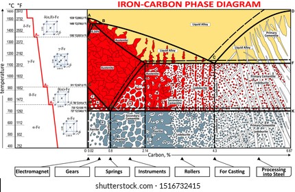
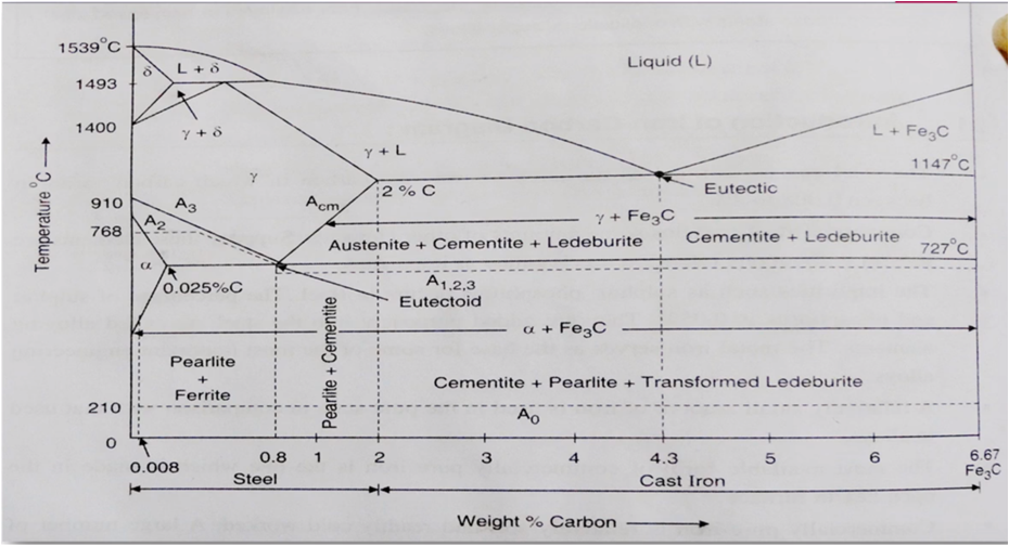
Iron-Carbon Phase Diagram with Detailed Explanation: If the percentage of the carbon is in the range of 0 to 2.11 % then it is called Steel and if the percentage of carbon is in the range of 2.11 to 6.67% then it is called Cast iron. As the carbon content increases, it produces more Iron-Carbide volume and that phase will exhibit high hardness.
![Iron-iron carbide phase diagram [234]. | Download Scientific Diagram](https://www.researchgate.net/profile/Seyyed-Shayan-Meysami/publication/260201931/figure/fig43/AS:614399152779270@1523495581488/Iron-iron-carbide-phase-diagram-234.png)
Iron-iron carbide phase diagram [234]. | download scientific diagram
The iron-iron carbide phase diagram is shown in the Animated Figure 10.28. Question: Compute the mass fraction of eutectoid ferrite in an iron-carbon alloy that contains 0.55 wt% C. The iron-iron carbide phase diagram is shown in the Animated Figure 10.28. This problem has been solved!
Apa kegunaan diagram fasa besi karbida? - quora
The Fe-C phase diagram is a fairly complex one, but we will only consider the steel part of the diagram, up to around 7% carbon. Page 2. Phases in Fe–Fe3C Phase ...7 pages
![Iron–iron carbide phase diagram [6, 7]. | Download Scientific Diagram](https://www.researchgate.net/profile/Shamail-Ahmed/publication/281806061/figure/download/fig1/AS:522846623498240@1501667757641/Iron-iron-carbide-phase-diagram-6-7.png)
Iron–iron carbide phase diagram [6, 7]. | download scientific diagram
iron when contains exactly 6.67% c by weight forms an intermediate phase called cementite or iron carbide (fe3c). hence, the iron-carbon equilibrium diagram is actually called as the iron - iron carbide equilibrium diagram with pure iron and pure fe3c (iron carbide) forming the extremities. actually, the phase fe3c (iron carbide) is called meta …
File:iron carbon phase diagram.svg - wikipedia
the iron-iron carbide diagram a map of the temperature at which different phase changes occur on very slow heating and cooling in relation to carbon, is called iron- carbon diagram. iron- carbon diagram shows the type of alloys formed under very slow cooling, proper heat-treatment temperature and how the properties of steels and cast irons …
![Iron-Carbon Phase Diagram Explained [with Graphs]](https://fractory.com/wp-content/uploads/2020/03/Phase-diagram-of-steel-and-cast-iron.jpg)
Iron-carbon phase diagram explained [with graphs]
Transcribed image text: (Include this page in your report) Answer the questions using Iron-Carbide phase diagram? 0.18% . 1493 - Austenite Aste Come Ledwchart Ceme Lederrie Temperature, 910 F A I! 723 Cemente Parte Transformed dette Ferrite + Pearlite Cementite Pearlite 0.76 20 12345 Hype-elected 4.3% 6.67% Cast Iron Percentage of Carbon, % a) What is the melting point of: Pure Iron 0.76% C ...
Practical maintenance » blog archive » the iron-iron carbide ...

Iron-carbon phase diagram (a review) see callister chapter 9 pages ...

Please answer the following question regarding the iron-iron ...

7 iron carbon phase ideas | carbon, iron, mechanical engineering
Bisakah anda menjelaskan diagram besi karbida besi (diagram besi ...
![Iron-carbon phase diagram [SubsTech]](https://www.substech.com/dokuwiki/lib/exe/fetch.php?w=&h=&cache=cache&media=iron-carbon_diagram.png)
Iron-carbon phase diagram [substech]

Fallsem2017-18_mee1005_eth_mb211_vl2017181003366_reference ...
Solved the iron-iron carbide phase diagram is shown below. | chegg.com
![4: The iron carbide phase diagram [38] | Download Scientific Diagram](https://www.researchgate.net/profile/Rakan-Alturk-2/publication/339508398/figure/fig1/AS:862829313814531@1582725947955/The-iron-carbide-phase-diagram-38.png)
4: the iron carbide phase diagram [38] | download scientific diagram
Iron iron carbide diagram | phase diagram | fe-fe3c diagram

The iron carbon phase diagram
Practical maintenance » blog archive » the iron-iron carbide ...

File:iron carbon phase diagram.svg - wikimedia commons
Solved question 2 given the iron-iron carbide phase diagram ...

Mod-01 lec-23 iron-carbon phase diagram

Gate metallurgical engineering: iron-iron carbide phase diagram
Iron carbide equilibrium diagram | marine inbox
1 the iron-iron carbide phase diagram [17]. | download scientific ...

Iron carbon phase diagram diagram | quizlet
Iron-iron carbide phase diagram example
Phase diagram iron carbon | metallurgy for dummies
Solved) - in the iron—iron carbide phase diagram of figure 6.4 ...
0 Response to "37 iron-iron carbide phase diagram"
Post a Comment