42 4 in 1 esc wiring diagram
Racerstar Crazybee F3 Flight Controller 4 IN 1 5A 1S Blheli_S ESC Compatible Frsky D8 Receiver. 20x20mm Racerstar TaiChi Round Stack F4 OSD 2-6S Flight Controller AIO BEC & 40A BL_32 4in1 ESC for RC Drone FPV Racing. First time builder here and I'm pretty lost with regard to the wiring. It seems like there's so much terminology and vernacular, it's all hard to keep straight. I'm trying to make a long range quadcopter with the following parts Controller: [http://jhemcu.com/e\_productshow/?17-JHEMCU-GHF411AIO-F4-OSD-FLIGHT-CONTROLLER-BUILT-IN-30A-BL\_S-2-4S-4IN1-ESC-FOR-TOOTHPICK-17.html](http://jhemcu.com/e_productshow/?17-JHEMCU-GHF411AIO-F4-OSD-FLIGHT-CONTROLLER-BUILT-IN-30A-BL_S-2-4S-4IN1-ESC-FOR-TOOTHPI...
22 Mar 2020 — Strangely, the wiring diagram isn't provided with the ESC – the instructions tell you not to kill yourself flying it (thanks), ...
4 in 1 esc wiring diagram
I recently bought the brake reduction module from MlToys [Brake Reduction Module (mltoys.com)](https://www.mltoys.com/product-p/brake-reduction.htm) However I found out that the pedal in my power wheel only has 2 cables, according to this tutorial video the pedal needs 3 cables in order to work (it doesnt say why) [MLToys Brake Reduction Module Installation - YouTube](https://www.youtube.com/watch?v=7liQNnmiAnY) Does anyone have the circuit of a pedal with the 3 cables? Currently My pe... Of the 2 diagrams you posted, would I be wiring the ESC to the FC using the bottom diagram (4in1 ESC w/individual current sensor)? The 4-in-1 ESC uses F3 processing power to allow complex power management without a hitch. The ESC supports up to 6S input voltage while 45 amps continuous support gives you plenty of headroom to push your mini quads to the limit. The XILO Stax FC has the unique ability to mount XM+ and Crossfire Nano style receivers directly to the FC.
4 in 1 esc wiring diagram. Lumenier 35A 4-in-1 ESC to CLRacing F4s JST Wiring Diagram. Close. 30. Posted by 4 years ago. Archived. Lumenier 35A 4-in-1 ESC to CLRacing F4s JST Wiring Diagram. 8 comments. share. save. hide. report. 94% Upvoted. This thread is archived. New comments cannot be posted and votes cannot be cast. Sort by: best. Drone Wiring Confusion (4in1 esc with a Pixhawk 4) Hello there, I'm a 1st time drone builder and am having some troubles getting my head around all of the wiring. The above picture is a picture of my schematics for the whole drone. As you can see in the bottom right, I have not yet shown the wires connecting the (4in1) esc to the pixhawk 4 as I ... To start off, my build costed much more than planned (over 300) and I might have found an easier cheaper way to do this project. * First option is a DIY RC system (\~$334) * Second Cheaper option is a pre-made RC System that is pre-packed for only $60 ([https://www.amazon.com/dp/B07ZMNXSQR/](https://www.amazon.com/dp/B07ZMNXSQR/?coliid=I3PK8KSHVD60J1&colid=T9YQEGAJEPNT&psc=1&ref_=lv_ov_lig_dp_it)) For the second option, I haven't tested it but if I had known about it before hand... Today I hope to clear up any confusion I have created in wiring a 4 in 1 ESC to your motors and flight controller. All the stuffs I useTranis X9D Plus http:/...
Note that you will probably need to redirect the PWM outputs to your 4 in 1 ESC signal inputs. wiring_diagram. Could I provide power to the motors by wiring all ...1 answer · Top answer: I think yes, this is doable. In this diagram you can replace the ESC Motor 1 with your 4 in 1 iflight ESC. Note that you will probably need to redirect ... I am going to build a 3 inch as my first drone build, but how do I know if all the parts will work together. I was planning on using the [Jhemcu GHF420AIO](https://www.banggood.com/20x20mm-Jhemcu-GHF420AIO-F4-OSD-Flight-Controller-w-or-5V-9V-BEC-Output-and-Built-in-35A-BL_S-4In1-Brushless-ESC-Support-DJI-Air-Unit-for-RC-Drone-FPV-Racing-p-1742882.html?cur_warehouse=CN&rmmds=search) flight controller/ESC with the [Spectrum DSMX Receiver](https://www.amazon.com/Spektrum-SRXL2-Serial-Receiver... Hi there! I'm building a drone for a high school project and for my analysis I need to read the current draw. My ESC, a iFlight SucceX-E Mini 35A 4-in-1, has a built-in current sensor which I'd like to read with my Arduino Uno that I also use as a flight controller. The problem is that I can't find any documentation regarding what protocol is being used here so I'm not sure how to read it. The only thing I found is a wiring diagram with one of the pins marked as *CUR* so I assume that's the one... SucceX 50A 2-6S BLHeli_32 Dshot 600 4-in-1 ESC Features: - 8 layers double-sided PCB board; - 4oz 1.6mm thick power board(0.9mm copper ratio),better operating load capacity;
click on the esc you have to obtain a sound system esc specific wiring diagram. rcs esc wiring diagrams for popular sound systems. dallee mylocosound phoenix p5: phoenix p8: phoenix pb9: sierra ***** part # 1. click on the type of r/c & esc you have for text instructions & wiring diagram. ... If you are using a compatible 4-in-1 ESC, then simply plug the SH header wire into the socket on the Kakute and the ESC. If you are not using a compatible 4-in-1 ESC, plug the SH header wire into the socket on the Kakute. Then: Solder the 1st wire (top-most in the picture) to a battery voltage (vBat) pad on your PDB or 4-in-1 ESC. The Betaflight F3 is a fantastic board, but how do you wire it up if you are using a 4-in-1 ESC? How do you get current sensing to work? It's actually not too difficult, and I'll show you how. If you just want to skip to the actual wiring diagram, jump to 14:30. Assuming you mean the T-Motor F55A Pro 4-in-1 ESC, using the white 10-pin and 8-pin ESC connectors on each board respectively, wire it in the following way. You can of course just solder directly to the pads with the same labels on the LUX F7 instead of using the white 8-pin connector if that is going to be easier.
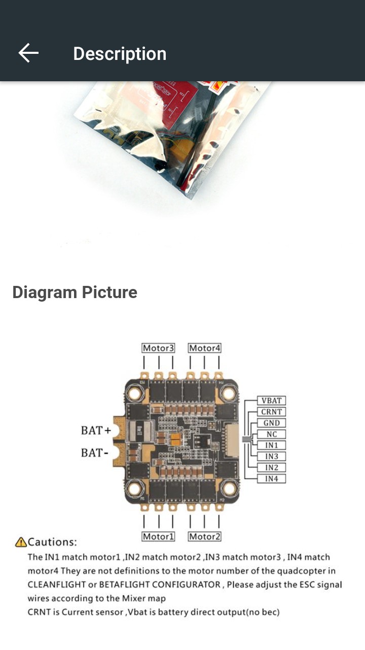
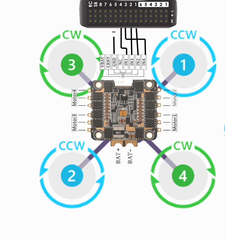
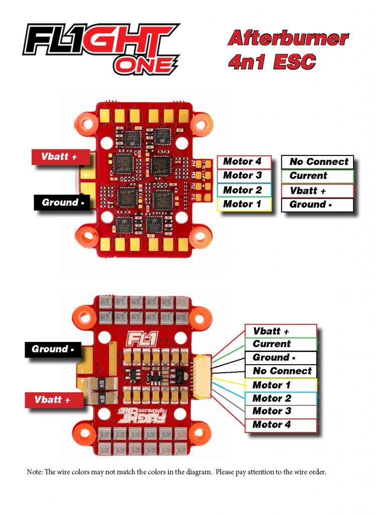
4 in 1 esc wiring diagram.For bit 4in1 ESC. Airbot Ori32 BLHeli32 25A 4-in-1 20×20 ESC Includes breakout cables. 4 in 1 esc wiring diagram. Lumenier F4 Aio Flight Controller F4 Osd Pdb Curr V Reg Control What Is Your Goal Fpv
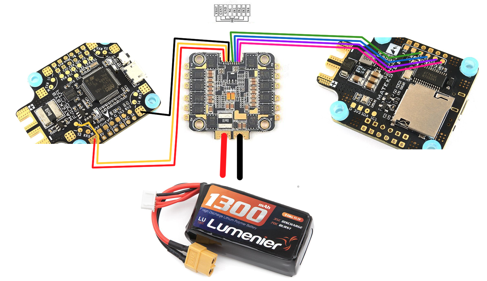
I'm having trouble getting power to the FC For the ribbon cable it should go: GND to GND VBAT to VCC M1 to S1 M2 to S2 M3 to S3 M4 to S4 CUR to CUR and TX to RX6 (? its the last option) Is that right? ​ Here are the wiring diagrams. ​ Thank you! ​ [https://shop.iflight-rc.com/succex-60a-plus-v2.1-2-6s-blheli-32-dshot1200-4-in-1-esc-pro694](https://shop.iflight-rc.com/succex-60a-plus-v2.1-2-6s-blheli-32-dshot1200-4-in-1-esc-pro694) [https://cdn....
Hello, I am putting together a drone using the following parts: * PixHawk 4 * Power management board (PMB) * EMAX 2213 motors * DJI E-430 Lite ESCs I am a bit confused the he ESC to PMB wiring. In older PixHawks the ESCs would connect directly to headers "in" the body of the PixHawk body, but with the PixHawk 4 this has moved to the PMB. Here is a picture of my current wiring setup: [I haven't actually connected the wires but I just wanted to show a visual of what it looks like.](https:...

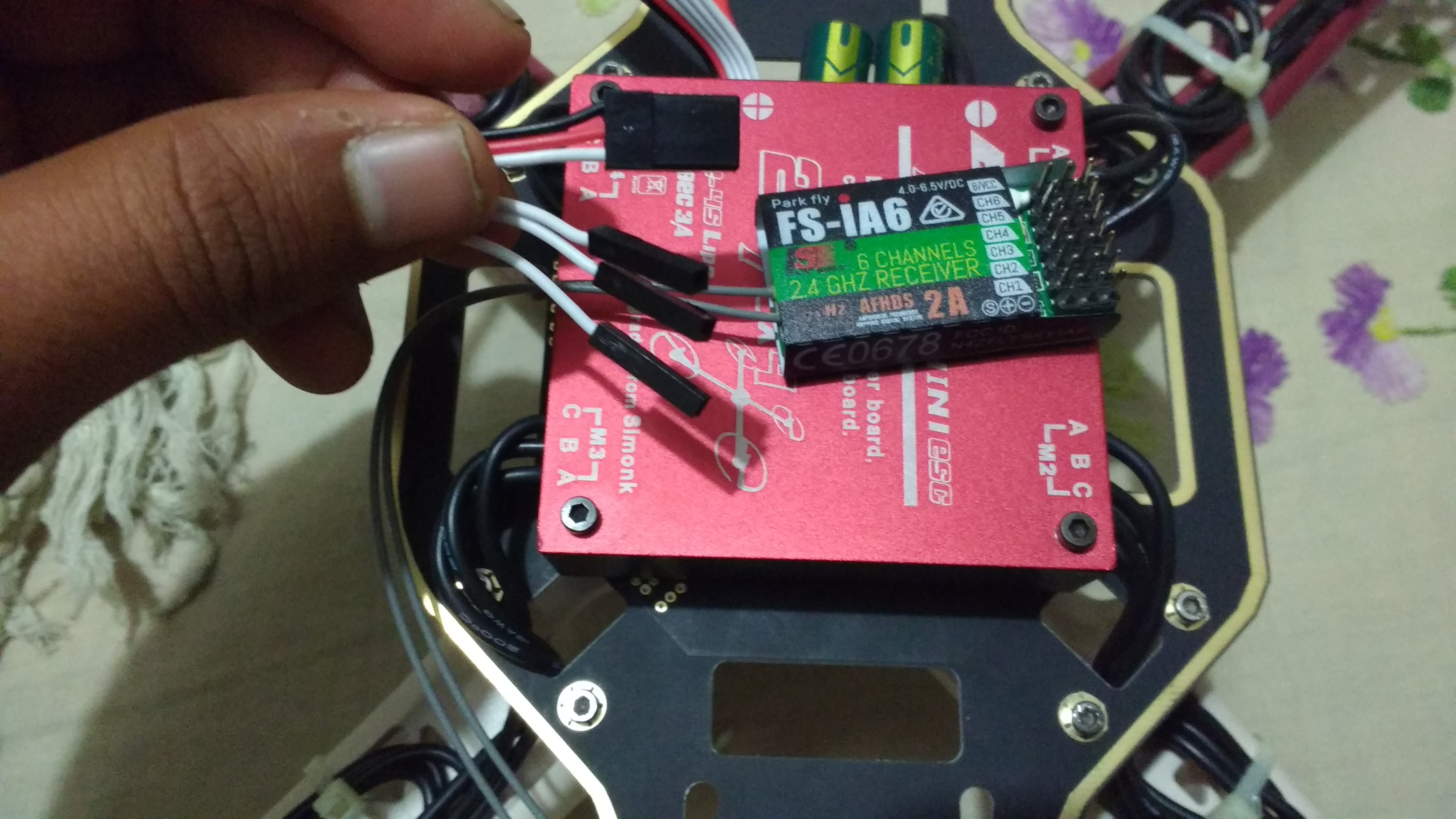
I am building a quadcopter as an end of the year project for my engineering class. I bought the FC and 4 in one ESC from IFlight, so the fit together with one of the provided cables, but I was given the receiver and controller from my teacher, and I cannot figure out how to wire it together. None of the wiring diagrams the came with the FC match the ORX R615x I was given. I have attached pictures below. I also might need help with config on betaflight, but i think wiring is going to be my first ...

[Here's my new FC stack.](https://www.racedayquads.com/products/flywoo-goku-f411-hex-2-4s-16x16-stack-combo-for-hexacopters-f411hex-fc-13a-6in1-esc) It doesn't really have instructions/explanations of any kind, just the wiring diagram we can see. I don't get why it would have VCC when the ESC pcb already has an incoming battery line- similarly it has motor signal pads. I ignored those assuming they are in case you want to instead use an external electronics. But am I wrong to assume all conn...
#**[Timestamps](https://imgur.com/a/Evk6gvg)** All prices include first-class shipping, CONUS only. I encourage asking for Priority for $5 more to avoid delays. I will consider messages in the order they come in, but timely bundle offers may get priority. Comment before messaging, no chat please.   |Boards/Keycaps|Details|Price|Available| |:--|:--|:-:|:-:| |~~R1 Grey Klippe T R4 + Boardwalk~~|~~Built with Boardwalk PCB and brass plate with MX housing NK Blueberries, 68g sprit spring...
Meet XROTOR "FPV" Series - 20x20 4 in 1 stack ESC Model 20x20 Stack 40A 20x20 stack Nano (20A) SKU 30902045 30901068 BLHeli_32 DShot1200 BLHeli-S DShot600 Application 130-300mm FPVsDiagonal Wheelbase 130-280mm FPVsDiagonal Wheelbase Firmware HobbywingXRotor_BLHeli32 BLHeli-S A-H-50 16.5 LiPo Power input 3-6S Lipo 2-4S
Hello I believe I have an electrical problem with my 2010 Jeep Patriot that’s been randomly going limp (loss of power, not able to accelerate) while throwing up the Electronic Stability Control malfunction/ indicator light. It’s been doing this for at least 6 months. Throughout that time I’ve also seen the ABS, 4WD and the electronic throttle control light come on along with the ESC light. I want to see if there’s an electrical issue. 1) Has anyone seen the above symptoms in a Jeep Patriot ...
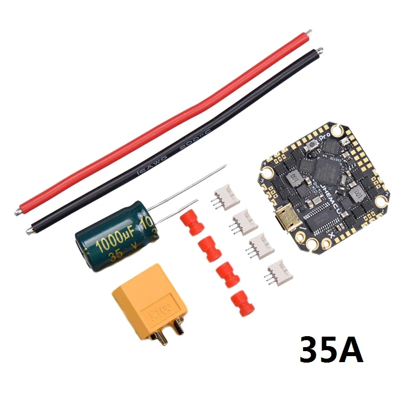
Dimensions: 33x46x5mm. Mounting holes: 20x20 M3. Signal wire: 7cm. Weight: 12.5g. 8pin connector pinout: VBAT, Ground, Current ADC, TLM, Motor 1, Motor 2, Motor 3, Motor 4. Includes. 1x Lumenier Mini Razor 4in1 20x20 F3 BLHeli_32 45A 2-6s ESC. 1x 8pin micro JST-SH 7cm connector for 4in1 ESC to FC connection.

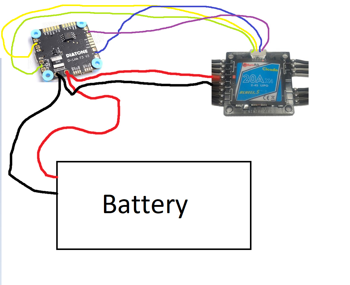
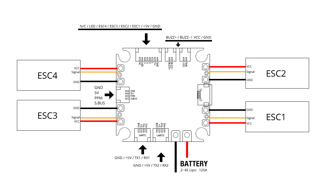
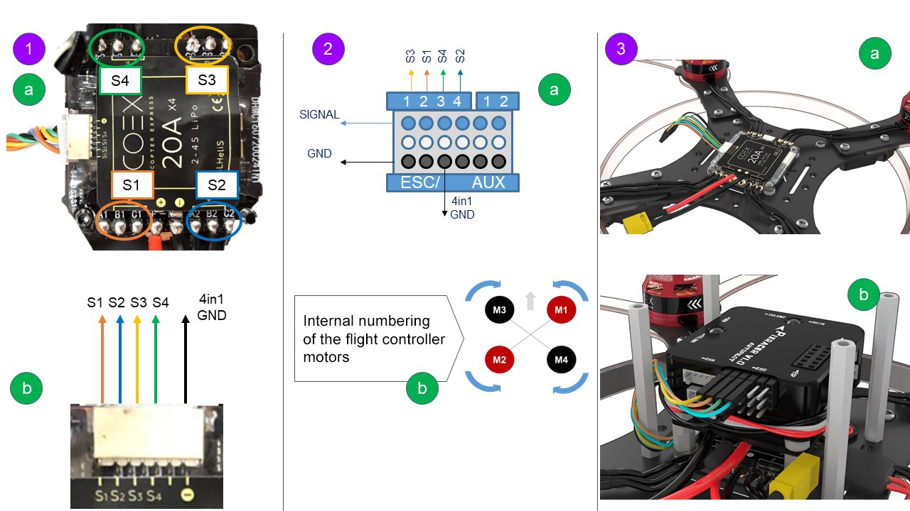
Connect three-wire cables from the ESCs to the PDB signal pins according to motor number. Connect the ESC for motor 1 to the PDB pins marked M1, motor 6's ESC to the pins marked M6, etc. This is an example about Esc and motor connect diagram, which is very detailed to show you that how to connect them. All the quadcopter wiring diagrams were ...

Hi all, beginner here posting with mod's approval. So I've built up a nice 3inch quad based on design specs from a much more experienced racer (cred to [David C.](https://www.thingiverse.com/dave_c_fpv/designs)) Motors: GePrc GR1408 3750kv FC/escs: Mamba F405 mini mk2 stack receiver: FrSky R-XSR vtx: eachine nano v2 Transmitter: FrSky X9 lite (The attached pic shows how I wired the R-XSR to the FC) So my issue, as the title describes, is that I can't seem to get betaflight to reco...
Hey guys, Really need some help. Built my dream quad with premium parts and it flips out (fly away) in a crazy clockwise spin. Tried everything (see below). Can’t figure it out. Its hard to believe that a brand new GepRC FC would fail on both gyros. Has to be something I missed. Not my first quad (I have about 6 flying great for over a year now). Was real careful in soldering temperature wise. See my build details below with links to build pics, Betaflight data, & troubleshooting. Haven’t ...

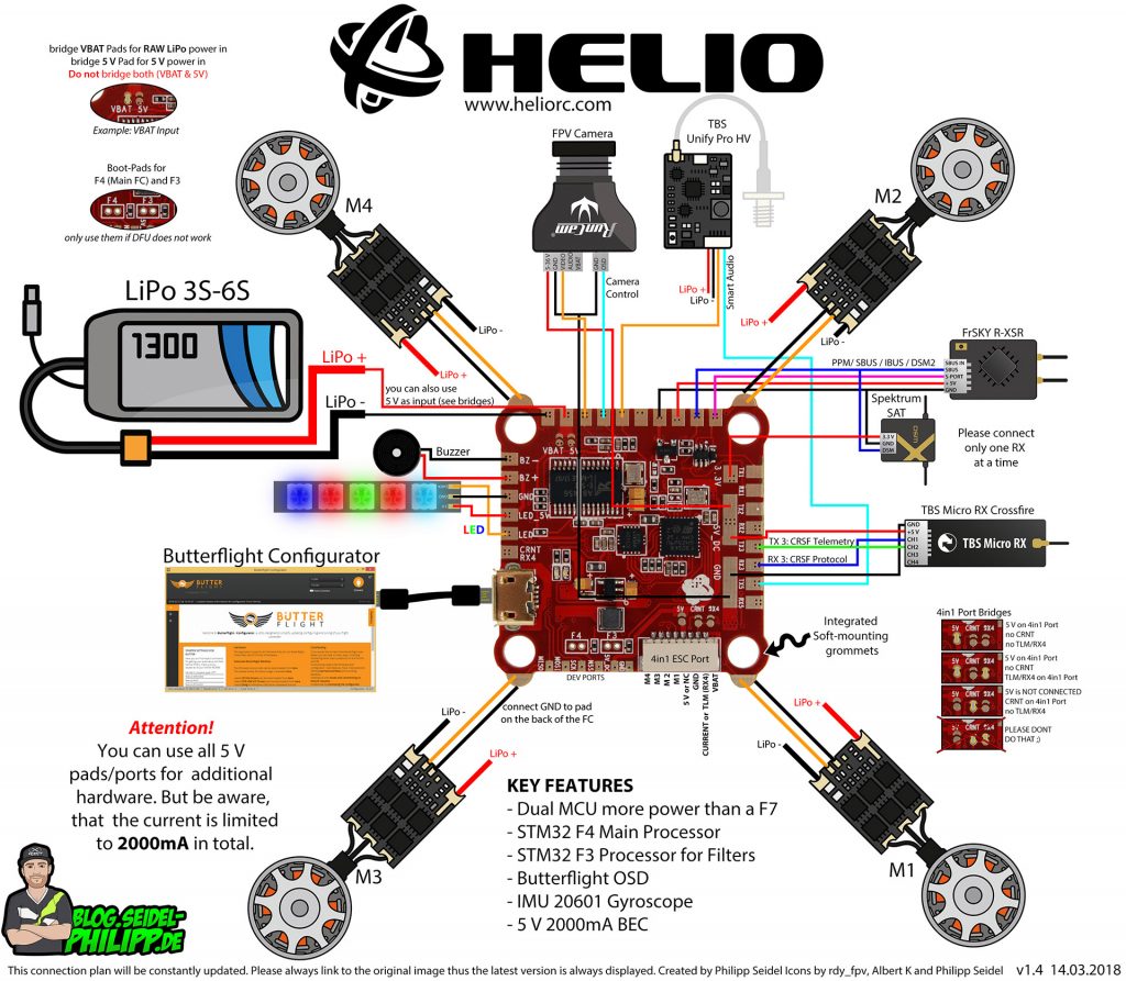
1) You can use it to power your FC, or RX, VTX, Camera, LED etc if your FC doesn't have a big enough 5V regulator. 2) ESC telemetry is passed to the FC using a i2c protocol, the ESC telemetry data is sent to the FC with an unique ID header, and the FC can tell which ESC the data is coming from by checking this id.
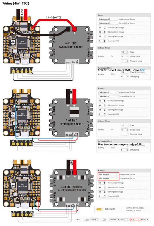
S1 - S4 - Motor Signal 1-4 TLM - Telemetry (Serial) GND - Reference Signal Ground ... On KISS FC v2 hardware and a firmware of at least 1.3RC38a the ESC can also be connected using Onewire protocol. ... The TLM wire has to be connected to an available serial TX pin. Page 7. Configuration In order to utilize ESC provided current and ...
I am going to build a 3 inch as my first drone build, but how do I know if all the parts will work together. I was planning on using the [Jhemcu GHF420AIO](https://www.banggood.com/20x20mm-Jhemcu-GHF420AIO-F4-OSD-Flight-Controller-w-or-5V-9V-BEC-Output-and-Built-in-35A-BL_S-4In1-Brushless-ESC-Support-DJI-Air-Unit-for-RC-Drone-FPV-Racing-p-1742882.html?cur_warehouse=CN&rmmds=search) flight controller/ESC with the [Spectrum DSMX Receiver](https://www.amazon.com/Spektrum-SRXL2-Serial-Receiver-...
After wading through the hot mess that is the different serial control/telemetry protocols (SBUS, S.Port, SmartPort, F.Port), I've ended up getting my R-XSR and F722 working with F.Port, however I'm not getting any telemetry. The receiver is running the [2.1.1 F.Port firmware](https://www.frsky-rc.com/r-xsr/) and BF is configured for FPORT and not SBUS. I've found many guides including [Oscar's](https://oscarliang.com/setup-frsky-fport/) and have followed them and still can't seem to get it wo...
Hello. I'm relatively new to FPV / multicopter building and wanted to ask a question about the way to connect my ESCs to my Flight Controller Board. On all the diagrams I've seen of wiring for the Mamba F405 Mk2 flight controller board, I am yet to understand how the ESCs connect (probably because I'm not very smart). My guess is that the four rings that are on the corners of the Flight Controller Board are used for connecting the ESC to the Flight Controller board, whilst the Positive and Neg...
XILO Stax F4 Flight Controller. 4.1 star rating. 17 Reviews. 10149. The XILO Stax F4 Flight Controller combines powerful F4 processing power with a host of features such as receiver mounting and VTX remote power switching. Plug n' play allows stacking with your favorite 4-in-1 ESC.

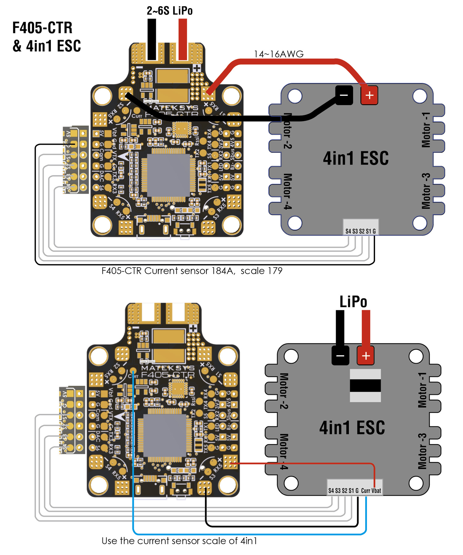
Matek F405 Ctr Wiring Diagram. However, if you have a 4 in 1 ESC, the connection might get a bit confusing. Just follow the diagram below: The battery is connected to the ESC. The FCTR flight controller is the latest iteration of the popular F family from Matek matek fctr flight controller wiring and configuration diagram.

Wiring anniversary special edition racestar rev35a Anniversary Special Edition Racerstar REV35 35A BLheli_S S 4 In 1 ESC. FC goes to in 1 on your ESC, and the same for according to the diagram @stevieteeLumenier BLHeli_32 32bit 35A 4-in-1 ESC s w/ BEC 3A/12v, 1A/5v, DSHOT A 4 in 1 version of Lumenier's 35A Blheli_32 ESC.

Brushless Esc Wiring Diagram . Brushless Esc Wiring Diagram . Circuit Diagram for Controlling Brushless Dc Motor Using. 48v 64v 1500w 45amax Dual Mode Sensor Sensorless Bldc Speed. Rc Timer 10 18 30 40a Esc Instruction
[https://i.imgur.com/2Oju3Ov.jpeg](https://i.imgur.com/2Oju3Ov.jpeg) # The research Open source software is my old love: not only linux but also used OpenTX (transmitter/receiver system) betaflight (drones), blheli (escs) and a bunch of another physical stuff. I actually love to build things from scratch: rc helicopters, rc drones, rc cars and even my own 3d o printer. So my journey to build a open source crypto hardware wallet begun with the question: >Is there any open source hardware w...
INAV2.5.x and Betaflight 4.2.x downloaded from configurator don't support new barometer DPS310. DPS310 has been supported officially by INAV2.6/ BetaFlight 4.3 and new configurator. For now, pls download customized BetaFlight 4.2.x from top-right "Firmwares" link
EDIT: I set up a soft serial using the LED_STRIP pin A15. Must have been a case of a broken RX pad on the VTX *and* a broken TX1 pad on the FC because I already tried using LED_STRIP pin A15 for IRC Tramp with the old VTX and it did not work, which led me to make this post after installing the new VTX on the TX1 pad did not work. AFAIK, the pin needs a timer to be used for VTX control; whether that be IRC Tramp or SA. I'm having issues with my [Jhemcu GHF411 Pro](https://www.racedayquads.com/pr...
TBS & Whitenoise X RACE WIRE PCB For 4in1 ESC & AIO FCs SPEDIX GS40 32BIT 4IN1 40A 6S BLHELI32 ESC .. Use the correct wiring diagram from schematron.org Note: When using a Millivolt V2 , . Airbot Ori32 BLHeli32 25A 4-in-1 20x20 ESC (Includes breakout cables). 1. For bit 4in1 ESC that supports ESC Telemetry, there should be only 1 TX pin.
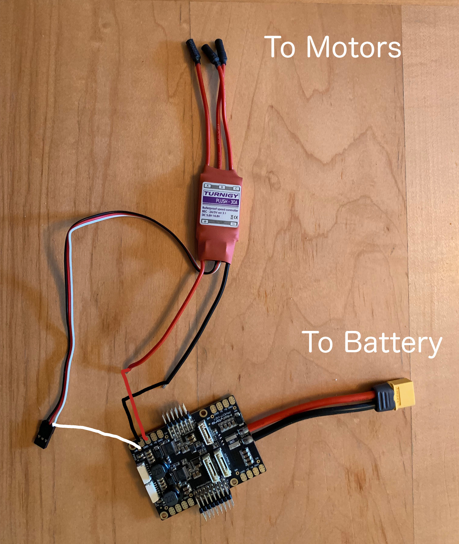
I fried my 4-in-1 ESC and am going to switch to individual ones so it's easier to fix when I break them in the future. I've chosen a PDB (MATEKSYS FCHUB-6s) because it specifically says it works with my FC (MATEKSYS f405-STD). On the wiring diagram it shows two big soldering pads for the power wires, then one for a control wire, but all of the ESCs I can find online have 4 wires coming out of them (or more). What are these wires?

I'm having trouble getting power to the FC For the ribbon cable it should go: GND to GND VBAT to VCC M1 to S1 M2 to S2 M3 to S3 M4 to S4 CUR to CUR and TX to RX6 (? its the last option) Is that right? ​ Here are the wiring diagrams. ​ Thank you! ​ [https://shop.iflight-rc.com/succex-60a-plus-v2.1-2-6s-blheli-32-dshot1200-4-in-1-esc-pro694](https://shop.iflight-rc.com/succex-60a-plus-v2.1-2-6s-blheli-32-dshot1200-4-in-1-esc-pro694) [https://cdn....

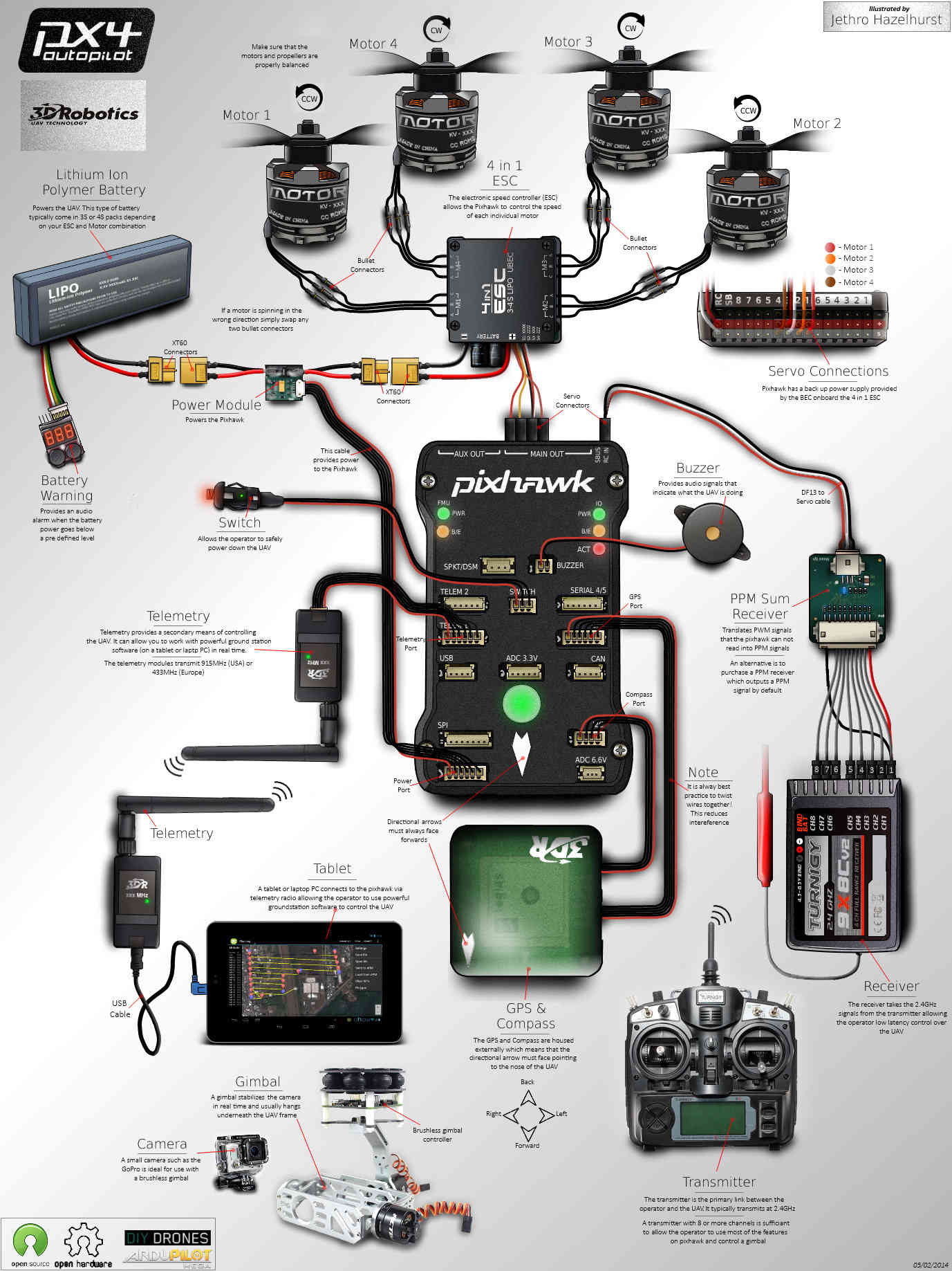
Flight Controller - 4-in-1 ESC Connections. Every 4-in-1 ESC currently available has the following connections: Motor Signals (S1 .. S4 or M1 .. M4): These connections are used to send RPM commands (how fast the motor should turn) from the flight controller to each ESC. With bi-directional DSHOT, the same wire is also used by the ESC to send RPM information back to the flight controller.
A 4in1 ESC is more convenient to use as there is less messy wiring as the powering of each ESC is done internally on the board. Typical connections on a 4in1 ESC As you can see in the diagram above for a typhoon ESC, there are 4 groups of 3 motor soldering tabs, so you would solder each motor to each group.
KISS ESC 25A 4-in-1 wiring. Wiring Diagram. 1. BLDC Motor phases (3) 2. Lipo Power Supply + 3. Lipo Power Supply - (GND) 4. 6-Pin JST connector - for direct connect to KISS FC. 5. ESC signal solder pads *1,2,3,4 - in light blue color is the numbering of ESC's. Top view. Previous.
beeps. Move the throttle stick to center (between 1.4 and 1.6ms). The controller will beep 2 times, indicating you have set the program selection or leave in full throttle for 5 seconds to advance to the next selection. b. To select 4-cell low voltage cutoff - You will hear 4 short beeps. Move the throttle stick to center (between 1.4 and 1.6ms).
ESC - (Amazon) - http://amzn.to/2s1aq5LESC - (Ebay) - https://rover.ebay.com/rover/1/711-53200-19255-/1?ff3=4&toolid=11800&pub=5575257854&campid=5338014988&...

See note below for connection to Pixhawk 4: M1: I/O PWM OUT 1: connect signal wire to ESC of motor 1 here : M2: I/O PWM OUT 2: connect signal wire to ESC of motor 2 here: M3: I/O PWM OUT 3: connect signal wire to ESC of motor 3 here: M4: I/O PWM OUT 4: connect signal wire to ESC of motor 4 here: M5: I/O PWM OUT 5: connect signal wire to ESC of ...

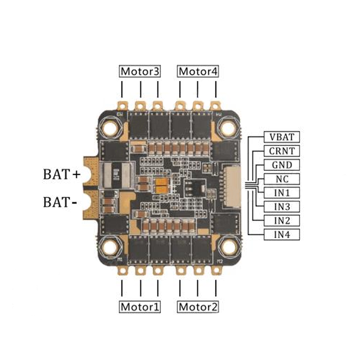
If your ESC has a current sensor, you must connect the corresponding wire to the CURR soldering pad. The motors 1, 2, 3 and 4 are connected respectively on pads S1, S2, S3 and S4. This diagram works for any FC that has an integrated PDB, such as DYS F4, BetaFlight F3, BetaFlight F4 or BetaFlight F7, and other AIO FCs available on the market.
The 4-in-1 ESC uses F3 processing power to allow complex power management without a hitch. The ESC supports up to 6S input voltage while 45 amps continuous support gives you plenty of headroom to push your mini quads to the limit. The XILO Stax FC has the unique ability to mount XM+ and Crossfire Nano style receivers directly to the FC.

Of the 2 diagrams you posted, would I be wiring the ESC to the FC using the bottom diagram (4in1 ESC w/individual current sensor)?
I recently bought the brake reduction module from MlToys [Brake Reduction Module (mltoys.com)](https://www.mltoys.com/product-p/brake-reduction.htm) However I found out that the pedal in my power wheel only has 2 cables, according to this tutorial video the pedal needs 3 cables in order to work (it doesnt say why) [MLToys Brake Reduction Module Installation - YouTube](https://www.youtube.com/watch?v=7liQNnmiAnY) Does anyone have the circuit of a pedal with the 3 cables? Currently My pe...


0 Response to "42 4 in 1 esc wiring diagram"
Post a Comment