42 arduino mega pinout diagram
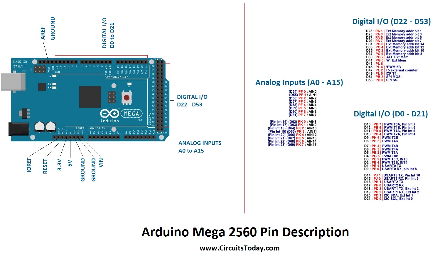
ARDUINO UNO Revision 3 Pinout (Uno PCB) - Commonly Used Features are printed on Silkscreen The Arduino Uno pinout is printed in the silkscreen on the top of the part. While this pinout is a good start, it does not explain the complete story - but it does give a good beginning. At first you use mainly the pins in the female headers at Arduino Mega Pinout — Of the 86 pins available on the Mega board, 72 pins are associated with input and output. In that 54 pins (D0 to D53) are true digital ...Digital IO Pins: 54 (of which 15 can produce P...Input Voltage: 6V – 20V (limit) 7V – 12V (reco...Analog Input Pins: 16Operating Voltage: 5V
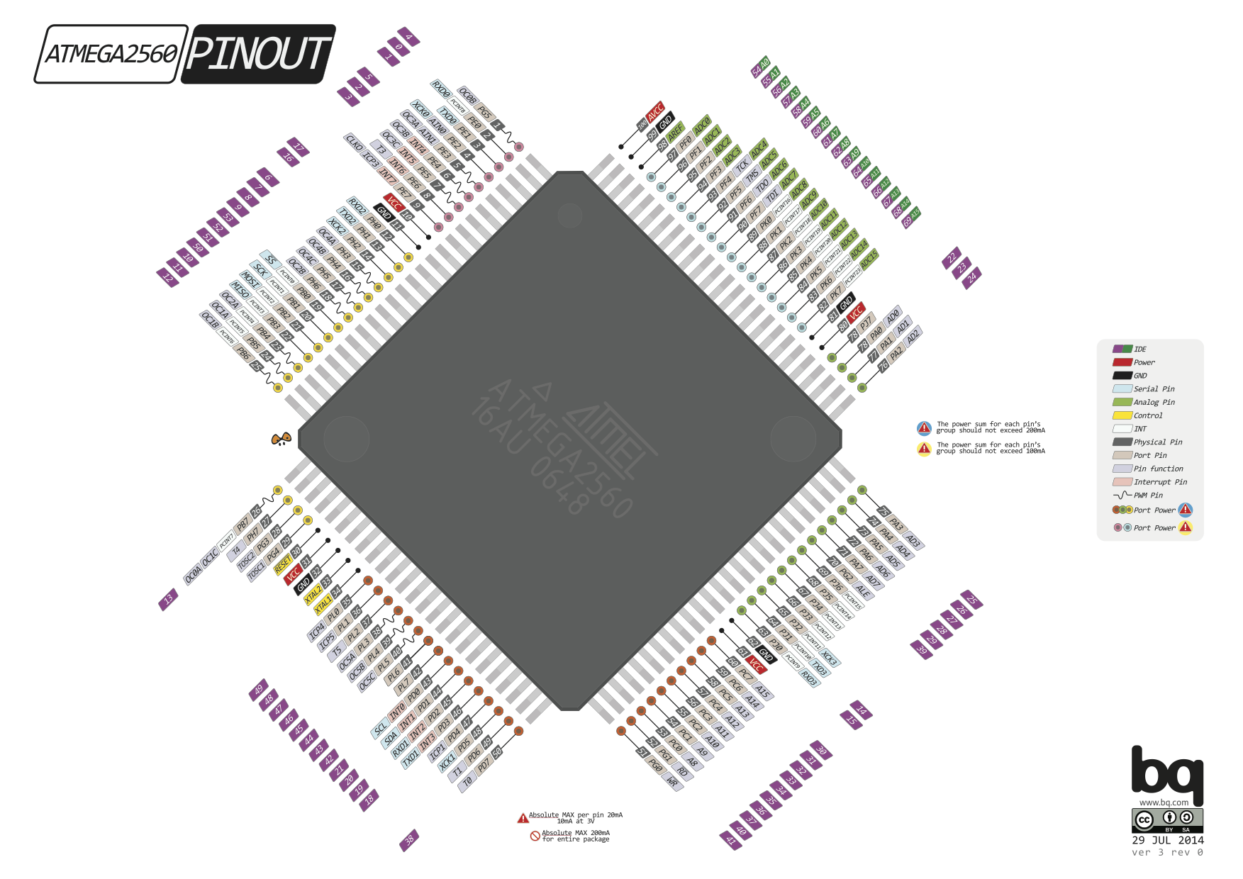
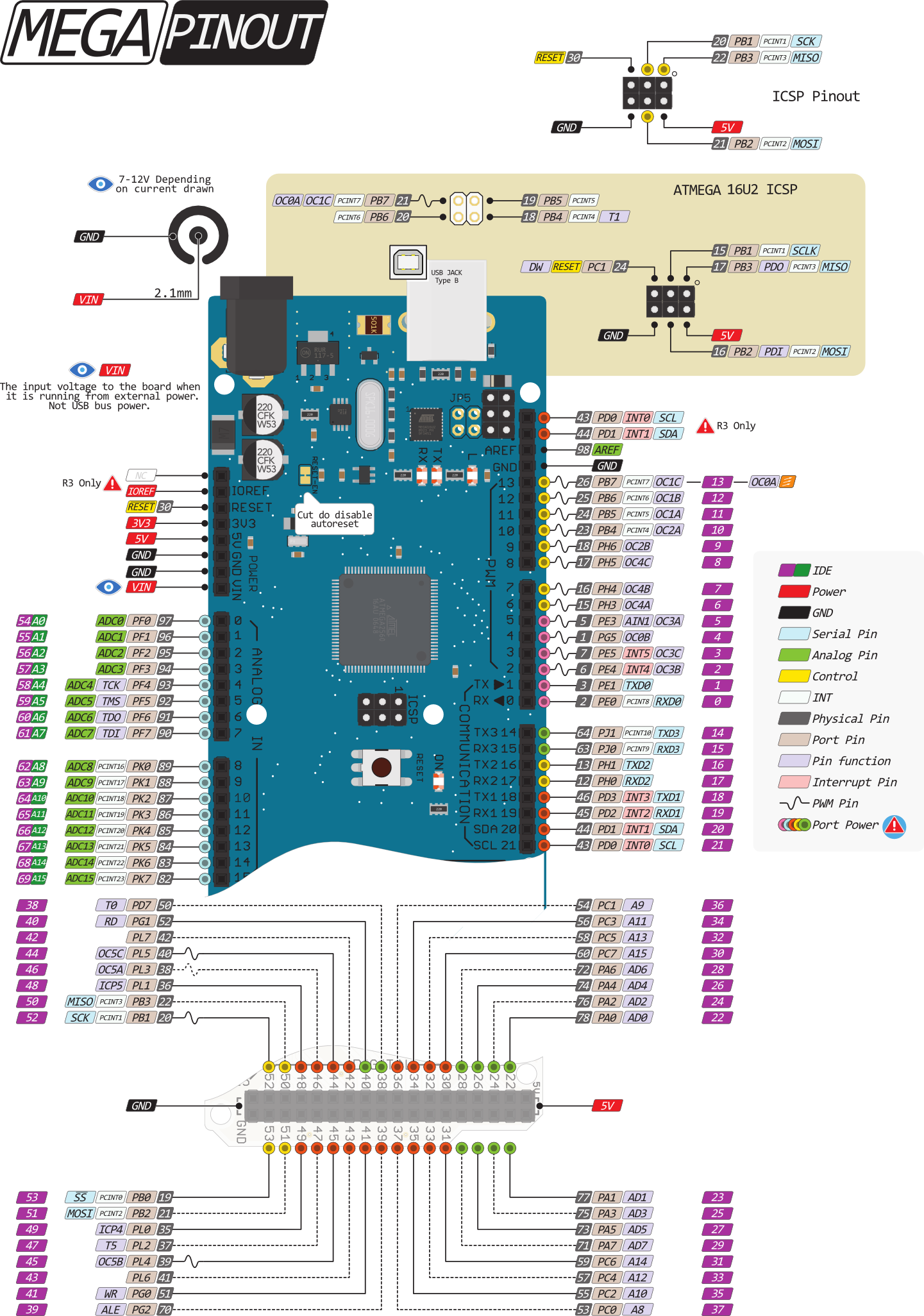
as promised, after the version of arduino uno, here is the diagram of Mega: NEW Version 2.0. Download Arduino MEGA v2. (old versions) Drawing is 1:1. for those who asked me, the version with the pin number (not 1:1) and the Pinout of ATMega2560. Download as PDF, PDF with pin number. and the ATMega 2560 Pinout PDF.

Arduino mega pinout diagram
Firstly, We will discuss the introduction, pinout, working, and connection diagram of the pulse sensor (SEN-11574) with Arduino. After that, we will three examples such as controlling LED with pulse rate, plotting data on serial monitor, and visualizing pulse sensor data with processing library. W can use this sensor to measure the heart beat rate (BPM). Additionally, by using a … Here are a number of highest rated Arduino Mega 2560 Diagram pictures upon internet. We identified it from reliable source. Its submitted by dealing out in the best field. We say you will this nice of Arduino Mega 2560 Diagram graphic could possibly be the most trending subject in the manner of we allowance it in google help or facebook. See also the mapping Arduino Mega 2560 PIN diagram. The Mega 2560 has 16 analog inputs, each of which provide 10 bits of resolution (i.e. 1024 different values). By default they measure from ground to 5 volts, though is it possible to change the upper end of their range using the AREF pin and analogReference () function.
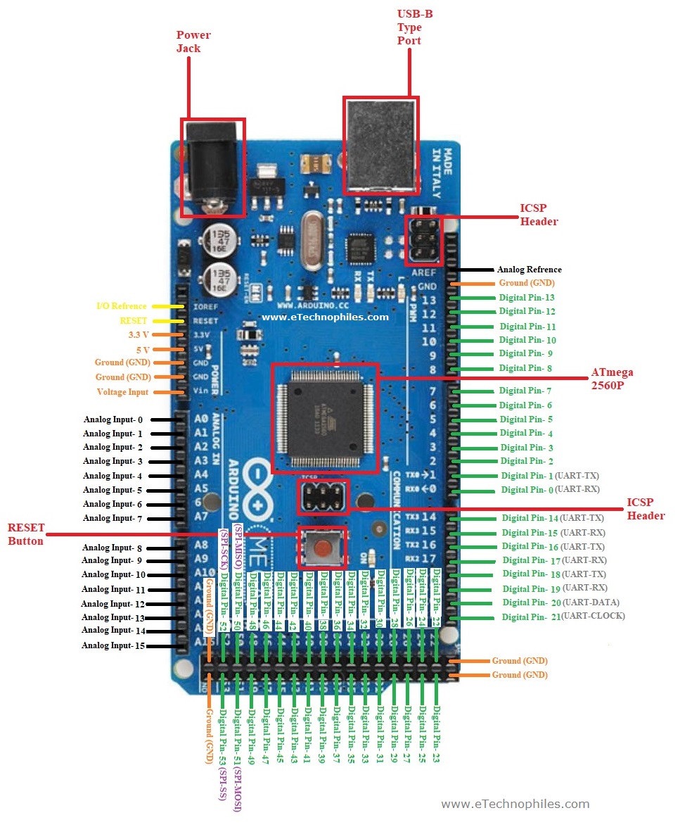
Arduino mega pinout diagram. Arduino Mega Pinout It consists of 54 digital input/output pins, where 16 pins are analog inputs, 14 are PWM pins, and 6 hardware serial ports (UARTs). It has a crystal oscillator-16 MHz, a power jack, an ICSP header, a USB-B port, and a RESET button. Voltage Regulator -The voltage regulator help to convert the input voltage to 5V. Diagram and Pinout. Before connecting, it is important to present the Arduino Leonardo's pinout and understand the intricacies of connection. Powering PINs: VIN - supplying voltage from an external power supply. This input has no connection to the five volt USB connector or other stabilization voltage. P. Marian. Input and Output. Each of the 54 digital pins on the Arduino 2560 Mega can be used as an input or output, using pinMode (), digitalWrite (), and digitalRead () functions. They operate at 5 volts. Each pin can provide or receive a maximum of 40 mA and has an internal pull-up resistor (disconnected by default) of 20-50 kOhms. Arduino® MEGA 2560 Rev3 5 / 1 8 Arduino® MEGA 2560 Rev3 Modified: 15/12/2021 1 The Board Arduino® Mega 2560 is a succesor board of Arduino Mega, it is dedicated to applications and projects that require large number of input output pins and the use cases which need high processing power. The Arduino® Mega 2560
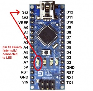
The Arduino Mega 2560 is a microcontroller board based on the ATmega2560. It has 54 digital input/output pins (of which 15 can be used as PWM outputs), 16 analog inputs, 4 UARTs (hardware serial ports), a 16 MHz crystal oscillator, a USB connection, a power jack, an ICSP header, and a reset button. Internal Pin. SWD Pin. Digital Pin. Analog Pin. Other Pin. Microcontroller's Port. Default. Last update: 16/12/2020. STORE.ARDUINO.CC/MEGA-2560-REV3. Arduino Mega 2560 Rev3 Pinout. In the following picture, you'll see the pinout diagram of Arduino Mega 2560 Rev3. The board incorporates 4 LEDs where one is a built-in LED connected to pin 13 of the board. One is a power LED that turns on when the board is turned on. While two LEDs are reserved for Rx and Tx which respond when the serial ... Contents. 1 Arduino / YourDuino MEGA 1280 and 2560 Diagram and Pinouts: 1.1 You can get the YourDuino Mega2560 HERE. 1.2 Arduino Mega 2560 Schematic Diagram (scrollable) 1.3 POWER PINS: 1.3.1 INPUT AND OUTPUT: 1.3.2 CONNECTIONS: 1.3.2.1 SPECIALIZED FUNCTIONS: 1.3.3 ANALOG PINS:
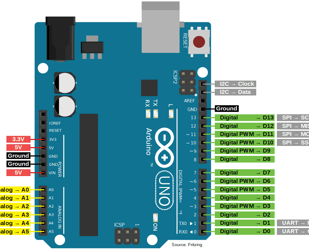
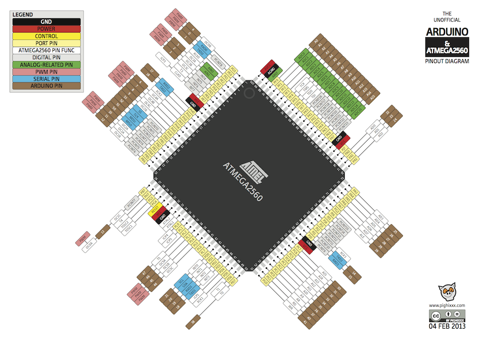
MEGA ARDUINO THE UNOFFICIAL PINOUT DIAGRAM 30 JAN 2013 www.pighixxx.com BY PIGHIXXX GND POWER PORT PIN ATMEGA PIN FUNC DIGITAL PIN ANALOG-RELATED PIN PWM PIN SERIAL PIN CONTROL PHYSICAL PIN LEGEND Pay Attention No Really PAY ATTENTION General Information LED version 1.0 05/02/2012 POWER JACK USB JACK GND VIN 7 - 12V depending Thank you. May I would suggest to add the PIN numbers as they are printed on the PCB (you did this on the UNO Reference), this would be easier to use if you don´t screw your Arduino to the printout ;) Thanks in advance. Matthias. Thanks! As soon as I have some time. mmcp42 February 4, 2013, 1:18pm #23. excellent stuff well done, sir! Arduino Mega Pinout for Beginners. Robert Brown · December 4, 2020. Arduino Mega 2560 is the flagman platform for development based on the ATmega2560 microcontroller. The board has everything you need for convenient microcontroller operation: 54 digital inputs/outputs, 16 analog inputs, USB programming slot, external power slot, and reset button. The Arduino Uno pinout guide includes information you need about the different pins of the Arduino Uno microcontroller and their uses: power supply, analog and digital pins and ICSP. The guide also discusses different communication protocols used by the Arduino and a detailed diagram of the Arduino Uno board.
Can't Get I2C to Work on an Arduino Nano? (Pinout Diagrams ...
Arduino Mega Diagram The Best Place To Get Wiring Diagram Arduino mega 2560 pinout diagram. Arduino mega 2560 r3 pinout diagram. This is the main controller used to program and run task for the system. Arduino mega schematic components. There are pin mappings to atmega8 and atmega 168328 as well. Dc jack power supply.

Arduino Mega 2560 Pin Diagram - General Wiring Diagram
Arduino Mega 2560 Pin Diagram 10.01.2019 3 Comments With 54 digital I/O pins, 16 analog inputs and a larger space for your sketch it is as PWM outputs), 16 analog inputs, 4 UARTs (hardware serial ports), a 16 MHz The Mega board is compatible with most shields designed for the Uno.

Okay, lets go!!!
Revision 3 of the Arduino board and the current Genuino Mega 2560 have the following improved features: 1.0 pinout: SDA and SCL pins - near to the AREF pin - and two other new pins placed near to the RESET pin, the IOREF that allow the shields to adapt to the voltage provided from the board.

(PDF) MEGA ARDUINO THE UNOFFICIAL PINOUT DIAGRAM GND POWER ...
arduino mega 2560 reference design reterence designs are pro vided "as is" and "wi th all faults disclaims all other warranties, express or implied, regarding products, including but not limited to , any implied warranties of merchantability or fitness fora particular purpose
![[KL_4339] Arduino Mega 2560 Pinout Schematic Wiring](https://static-cdn.imageservice.cloud/2762945/arduino-mega-2560-pinout-arduino-projects-in-2019-arduino.png)
[KL_4339] Arduino Mega 2560 Pinout Schematic Wiring
Arduino Mega Pinout Arduino Mega Pin Diagram Controller Pins: RESET: (Reset input) A low level on this pin for longer than the 4 clock cycle will generate a reset. Arduino Mega has inbuilt reset circuit with push button to reset system and this pin can be used by other devices to reset controller.

An Arduino MEGA and Leonardo Pinout Diagrams from the ...
Ramps 1.4 Pin Diagram. end stoppers. RAMPS Schematic, taken from schematron.org Install the Five Pololu steppers in the boxed pins shown on the left picture. Make sure. RepRap Arduino Mega Pololu Shield, or RAMPS for short. It is designed to fit the entire RAMPS uses the same pin definitions as You will need the.
I2C Tutorial for Arduino, ESP8266 and ESP32 - DIYI0T
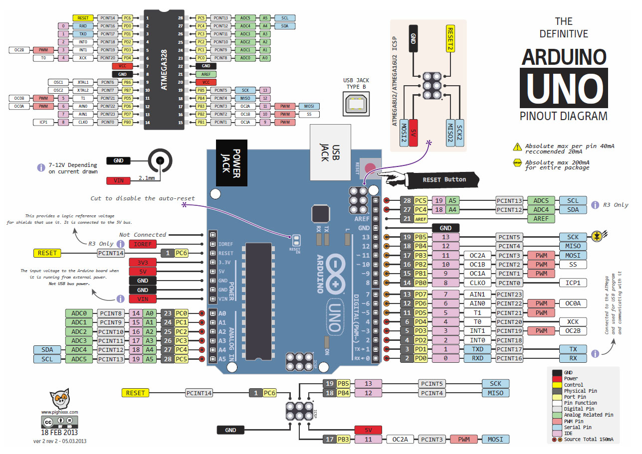
store.arduino.cc/uno-rev3 d12 ~d11 ~d10 ~d9 d8 d7 ~d6 ~d5 d4 ~d3 d2 d1/tx d0/rx pc6 reset adc[0] adc[1] adc[2] adc[3] adc[4] adc[5] pc0 pc1 pc2 pc3 pc4 pc5 d19/scl d18/sda aref gnd d13 pc5 pc4 pb5 pb4 pb3 pb2 pb1 pb0 pd7 pd6 pd5 pd4 pd3 pd2 pd1 pd0 scl sda sck cipo copi ss a5 a2 a1 a0d14 d15 a2 d16 d17 d18 d19 a0 a1 a3 a4 a5 ioref nc +3v3 +5v ...

AT MEGA 328 Arduino pinout Circuit Diagram | Electronic ...
Pinout ATmega1281/2561 Note: The large center pad underneath the QFN/MLF package is made of metal and internally connected to GND. It should be soldered or glued to the board to ensure good mechanical stability. If the center pad is left unconnected, the pack-age might loosen from the board. (RXD0/PCINT8/PDI) PE0 (TXD0/PDO) PE1 (XCK0/AIN0) PE2 (OC3A/AIN1) PE3 …

Arduino Uno Pinout Diagram | Make:
Arduino Pinout Diagrams. Last year I found some awesome Arduino pinout diagrams with full colour on the Arduino forums. They are all titled something like The Unofficial Arduino Pinout Diagram / The Definitive Arduino Pinout Diagram, etc. They disappeared from the Internet (pighixxx.com) in December 2013. With the help of the Internet Archive ...

Pinout Diagrams for the Arduino Uno and More « Adafruit ...
Arduino Mega Pin Diagram Arduino Mega Pin Configuration Controller Pins: RESET: (Reset input) A low level on this pin for longer than the 4 clock cycle will generate a reset. Arduino Mega has inbuilt reset circuit with push button to reset system and this pin can be used by other devices to reset controller.
![[BD_1712] Arduino Mega 2560 Pinout Schematic Wiring](https://static-cdn.imageservice.cloud/2762968/86duino-one-hardware-introduction-86duino.jpg)
[BD_1712] Arduino Mega 2560 Pinout Schematic Wiring
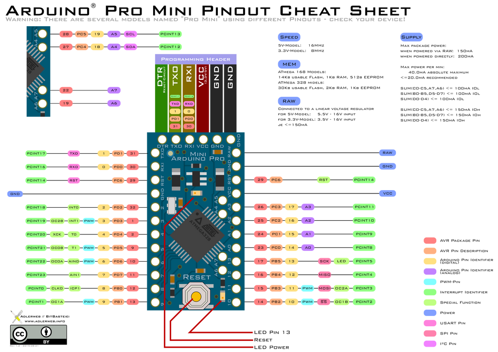
Pinout of Arduino MiniThe Arduino Mini is a small microcontroller board originally based on the ATmega168, but now supplied with the 328, intended for use on breadboards and when space is at a premium. It has 14 digital input/output pins (of which 6 can be used as PWM outputs), 8 analog inputs, and a 16 MHz crystal oscillator. It can be programmed with the USB Serial adapter or other USB or ...
![[KL_4339] Arduino Mega 2560 Pinout Schematic Wiring](https://static-cdn.imageservice.cloud/2762951/arduino-mega-for-beginners-projectiot123-technology-information.jpg)
[KL_4339] Arduino Mega 2560 Pinout Schematic Wiring
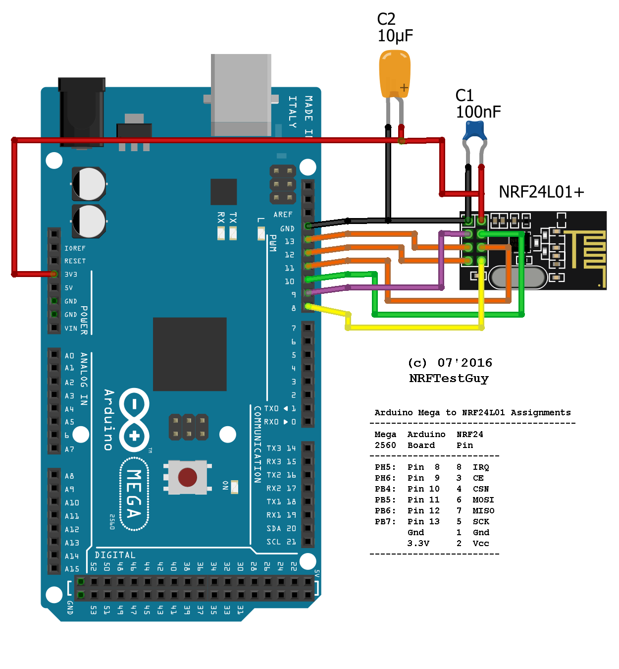
Arduino Mega Pinout Diagram IY Remote Control - Part 5 : Wiring 101 - Nova SpotMicro3 v5.2 Oh boy, i mean theres a lot going on here guys. This probably has to be the most intricate wiring project ive embarked on.

Arduino Uno Pinout Diagram | Arduino, The o'jays and Design
13 Mar 2013 — Analog Related Pin. PWM Pin. Serial Pin. IDE. Source Total 150mA. MEGA. ARDUINO. THE. DEFINITIVE. PINOUT DIAGRAM. Absolute max 200mA.1 page
Beautiful light bulb shot at Carrefour library section in Nakumatt Mega Mall.
Arduino Mega Pinout. Because the Mega is the biggest Arduino microcontroller, this beast has the highest number of pins and is therefore suitable for large projects where a lot of devices have to be connected to the microcontroller. The Arduino Mega has in total one 3.3V pin and four 5V pins, which are able to provide a current up to 50 mA.

PighiXXX — Arduino Pinout Diagrams
It is the most popular of all AVR controllers as it is used in ARDUINO boards. ATMega328 Pinout Configuration. ATMEGA328P is a 28 pin chip as shown in pin diagram above. Many pins of the chip here have more than one function. We will describe functions of each pin in below table. Pin No.

Arduino UNO Pinout Diagram | Arduino, Arduino projects ...
See also the mapping Arduino Mega 2560 PIN diagram. The Mega 2560 has 16 analog inputs, each of which provide 10 bits of resolution (i.e. 1024 different values). By default they measure from ground to 5 volts, though is it possible to change the upper end of their range using the AREF pin and analogReference () function.
Arduino Mega Wiring Diagram | New Wiring Resources 2019
Here are a number of highest rated Arduino Mega 2560 Diagram pictures upon internet. We identified it from reliable source. Its submitted by dealing out in the best field. We say you will this nice of Arduino Mega 2560 Diagram graphic could possibly be the most trending subject in the manner of we allowance it in google help or facebook.

Arduino – Mega pinout diagram | Arduino, Arduino board ...
Firstly, We will discuss the introduction, pinout, working, and connection diagram of the pulse sensor (SEN-11574) with Arduino. After that, we will three examples such as controlling LED with pulse rate, plotting data on serial monitor, and visualizing pulse sensor data with processing library. W can use this sensor to measure the heart beat rate (BPM). Additionally, by using a …

Manuals, Data Sheets, Diagram and Pinouts | 14core.com

Arduino Mega Pinout Diagram - Pcb Circuits
Manuals, Data Sheets, Diagram and Pinouts | 14core.com
![[BD_1712] Arduino Mega 2560 Pinout Schematic Wiring](https://static-assets.imageservice.cloud/2762967/kontroller-arduino-mega-2560-r3-original.jpg)
[BD_1712] Arduino Mega 2560 Pinout Schematic Wiring
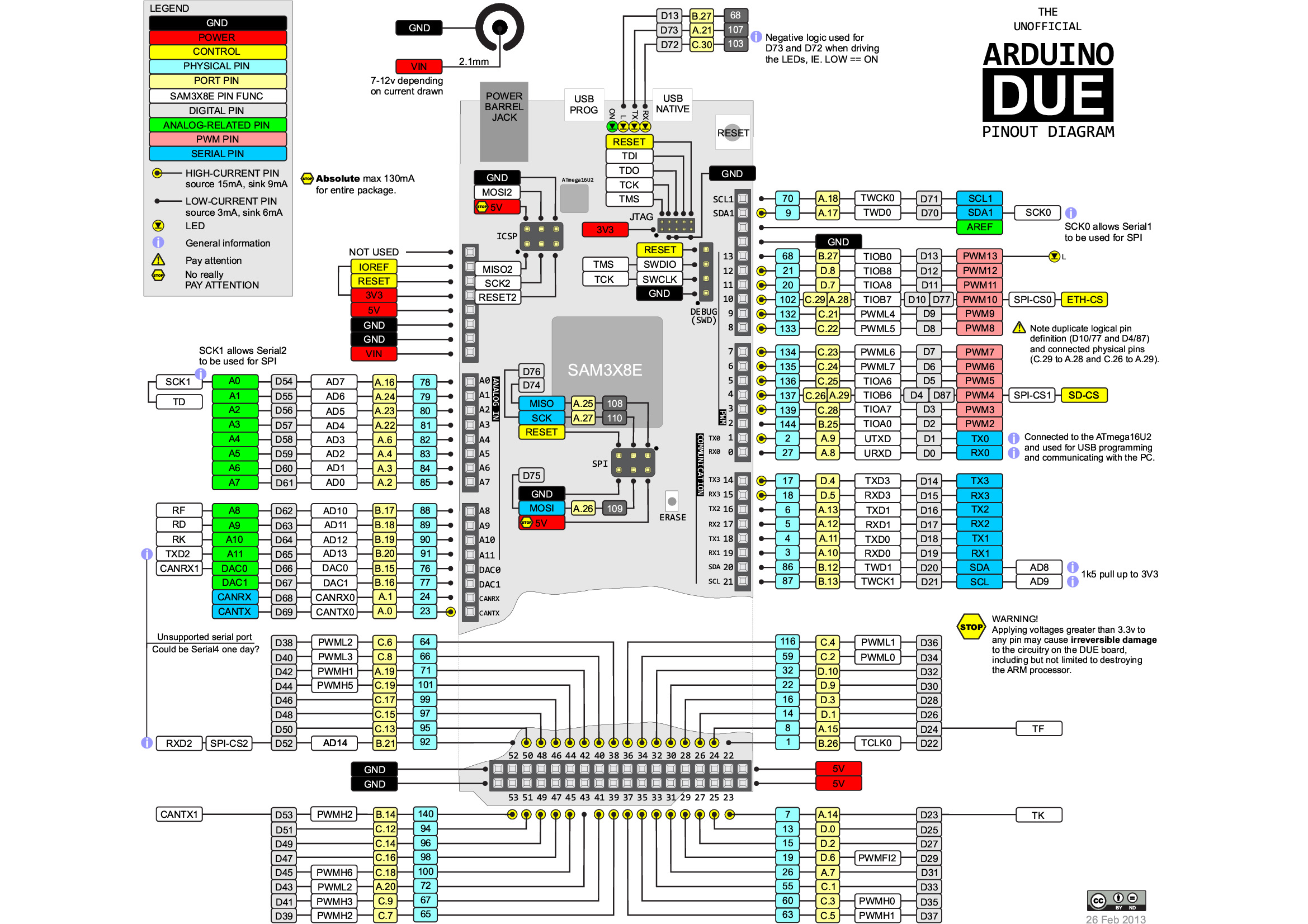
Arduino-Due-Pinout-Diagram-Illustration-Complete-Pin ...
Arduino Mega 2560 R3 Pinout Diagram - Hanenhuusholli

Arduino Uno Pinout Diagram : Arduino Mega Pinout Pin ...
Arduino Mega 2560 Wiring Diagram - Search Best 4K Wallpapers

The Official Arduino MEGA 2560 Schematics Diagram | 14core.com
Arduino Mega 2560 R3 Pinout Diagram - Free Diagram For Student

2 Channels Relay Test Using Arduino Mega and Ethernet ...
Arduino Mega Tutorial - Pinout and Schematics. Mega 2560 ...

Arduino Mega 2560 R3 Pinout Diagram - Hanenhuusholli

CNC Controller with Arduino, TB6600 and GRBL - Kalaakaar ...
Arduino first steps – www.wiki.ardumower.de
place to be
Arduino Mega 2560 Zeichnung - Circuit Boards

Circuit Notes: Arduino Uno

Arduino Mega Pins Layout - Pcb Circuits
Talking to LCD with only ATMEGA chip
33 Arduino Mega 2560 R3 Pinout Diagram - Wiring Diagram ...

Arduino Mega Tutorial - Pinout and Schematics. Mega 2560 ...
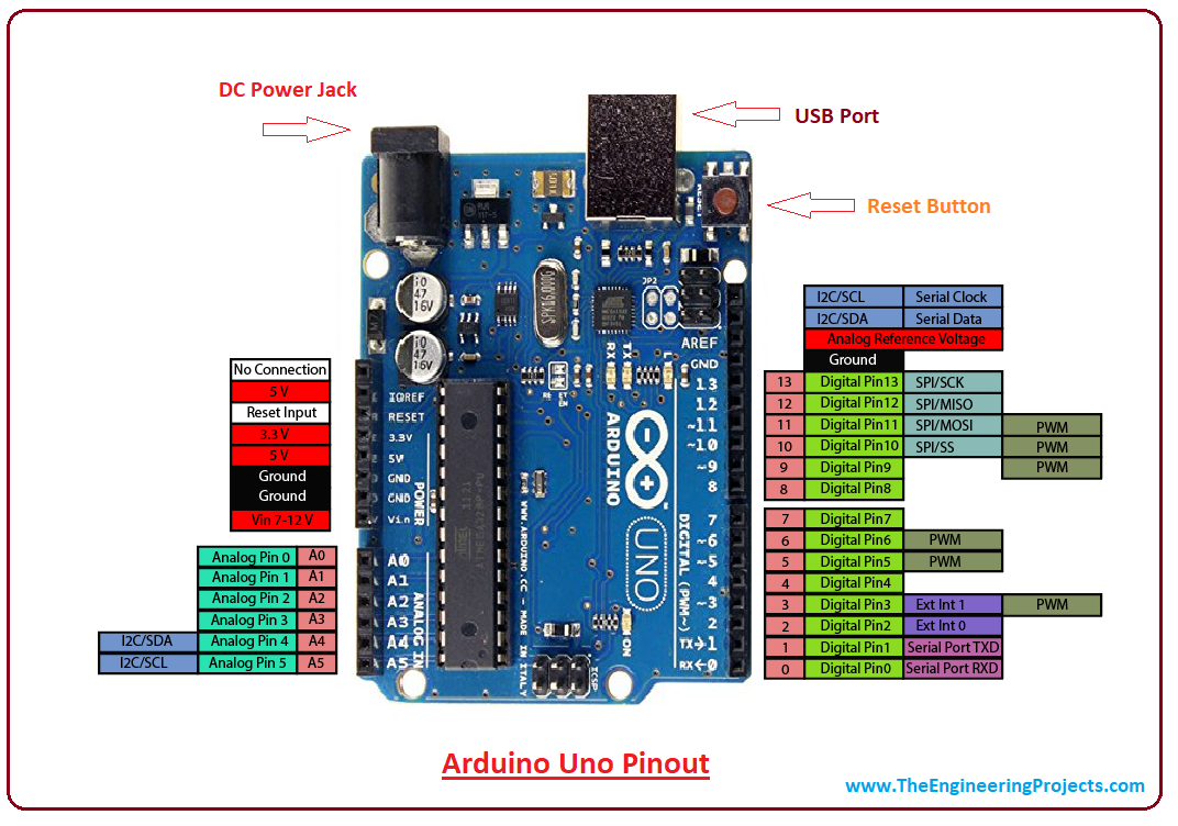
Introduction to Arduino Uno - The Engineering Projects
'Arduino(R)'-like Pro Mini Pinout Diagram by adlerweb on ...
0 Response to "42 arduino mega pinout diagram"
Post a Comment