38 ge rr7 relay wiring diagram
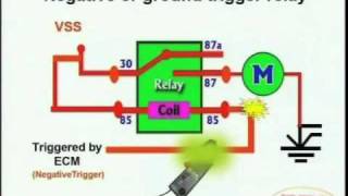
Problem with GE RR7 low voltage relay. | Terry Love Plumbing Advice ... The RR7 is a low-voltage controlled, latching relay that can control line voltage devices up to 277vac. The small red/blue/black attached leads are: Red - pulse on Black - pulse off Blue - common The above leads are all low-voltage signals from the transformer and switch. Favorite Dead End Three Way Switch Diagram Diy Rocker Panel Electrical Backfeed The pair of traveler wires. 3 way switch wiring diagram. In this diagram the incoming hot wire attaches to the first switch s common dark colored terminal. Tip look at how power is connected at lights. This 3 way switch wiring diagram shows how to wire the switches and the light when the power is coming to the light switch.
Amazon.com: GENERAL ELECTRIC GE RR7 REMOTE CONTROL 21-30V-AC RELAY : Appliances GENERAL ELECTRIC GE RR7 REMOTE CONTROL 21-30V-AC RELAY Visit the GE Store 54 ratings 20 Amp 24 VAC Class 2 › See more product details New (2) from $106.59 + $4.99 shipping Product Description GE General Electric RR-7 Remote Control Switching Relay, 21-30VAC, Momentary Product information Technical Details Additional Information Feedback

Ge rr7 relay wiring diagram
rr7 ge relay wiring diagram - Wiring Diagram free pdf search results latching relay i have a ge low voltage remote rr7 with blue black red wire am replacing the ceiling fan another light relays in lighting systems to control lights or motors system 24 emergency ul924 rated 277v contactor coil and an 8 group input module 48 capacity interior kele com controls rr7pbp contactors rr9p … Low Voltage Wiring Relay - Wiring Diagram Considerations when wiring low voltage control relays question. The relay contacts trip the circuit breaker when the voltage decreases to a certain level. Z to a avg. Touch plate goes back to the mid to late 1940s. Lighting control relay panels. High to low ge rr7 20a spst low voltage relay total lighting control. Looking Good Ats Wiring Diagram For Standby Generator Ge Rr7 Relay Marine ... This transfer switch is suitable for use on a circuit capable of 10 000 rms symmetrical amperes 240 vac maximum. It reveals the components of the circuit as streamlined forms and the power as well as signal connections in between the tools. A wiring diagram is a simplified conventional photographic depiction of an electric circuit.
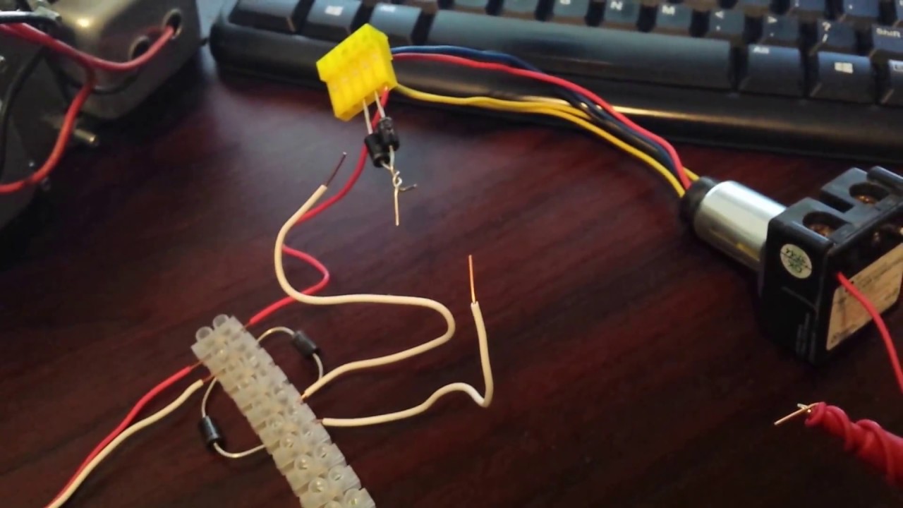
Ge rr7 relay wiring diagram. Matchless Single Phase Mcb Connection Fasco 9721 Wiring Diagram Lutron ... Pin On Jemal Ge Rr7 Relay Wiring Diagram. This is too important to install a double pole mcb breaker in our one phase distribution or mainboard. Two for entering the supply and two for output supply. And in this post i am gonna to share a mcb wiring connection diagram in which is shown the single pole double pole three pole and 4 mcb wiring ... Ge Rr4 Relay Wiring Diagram RR7. RR6. SGC 21A/B/C Negative-Sequence Time Overcurrent Relays. 2 other current is obtained from voltage divider R4, R5, R6, and passes through C2. By referring to the internal connection diagram for the card, it is possible to trace through. is provided. Rr7 Relay Wiring Diagram Rr7 Relay Wiring Diagram RR7 Sensors: How Can I Troubleshoot GE RR7 Relays And Sensor Switch You should measure about VDC at the red and black wires of the sensor. This makes remote switching of lighting circuits . RR7. Standard 3-wire relay with stripped leads. RR8. Pilot contact 4-wire relay with stripped leads. RR9. GE RR7 low voltage relay. I have low voltage wiring using GE rr7 relays. there are two relays which ... I have low voltage wiring using GE rr7 relays. there are two relays which will not work because a mouse ate the insulation around some of the spots where wires were tied together in the ceiling. I have exposed the wiring but can't get the wires connected correctly. Can you help? There are 4 flat 3-wire wires, the center wire on all are tied together.
Ge Rr7 Relay Diagram - Wiring Diagram Pictures See Three-wire to Touch-Plate® Wiring Diagram. 28VDC latching relay, whereas the the GE® relay (RR-7) is a dual coil, 24VAC latching relay, and the Remcon®.The relay should "click" and the Relay Indicator should change state. Confirm the operation by measuring the continuity at the line-voltage terminations of each relay. 2. RR-7, RR-9 | GE Mechanical Latching 24 VAC Lighting Relays - Kele The GE Model RR-7 and RR-9 lighting relays are mechanical latching-type units designed for building automation systems. Each relay requires only momentary 24 volt AC switch circuit pulses to open or close line voltage circuits. All GE low voltage relays may be used to full-rated capacity for tungsten filament, ballast, or resistive loads. 1- GE RR8 Remote Control Relay With Pilot Light Control - - Amazon.com GENERAL ELECTRIC GE RR7 REMOTE CONTROL 21-30V-AC RELAY. ... GE WIRING RR8 Remote Control Relay With Pilot Light 1/2 HP, 20A TUNG 125VAC 1-1/2 HP, 250VAC 20A-277VAC. Product information . Technical Details. Brand GE : Manufacturer GE Wiring : Part Number RR8 : Ge Rr8 Relay Wiring Diagram Collection - Wiring Diagram Sample Name: ge rr8 relay wiring diagram - Ge Rr7 Wiring Diagram Relay 5 Pin Wiring Diagram Co Co Relay Remote; File Type: JPG; Source: suaiphone.org; Size: 153.74 KB; Dimension: 990 x 728; What's Wiring Diagram. A wiring diagram is a schematic which uses abstract pictorial symbols to show all of the interconnections of components in a very system.
Ge Timer Switch Wiring Diagram - easywiring Like the original models the rr7 is a standard solenoid relay designed for use with ge rs series unlighted switches. Hotpoint Dryer Timer Wiring Diagram Reference Of Ge Cooktop Wiring. The Intermatic was using 2 hots 1 neutral and ground. Ge Rr9 Wiring Diagram Thats why were showing this topic at the moment. GE Model RR-7 and RR-9 lighting relays are mechanical latching-type units requiring only momentary 24 VAC switch circuit pulses to open or close line voltage circuits. All GE low voltage relays may be used to full-rated capacity for tungsten filament, ballast, or resistive loads. GE Current - RR9, Enclosed Relays - PLATT Pilot Control Relays. For help with Relay Module 20A277V from GE Current. Also known as: GELRR9., GE Current, RR9, Enclosed Relays - Pilot Control, Enclosed Relays, Relays, Control, Automation. Average Rating: (0/5) Write Review. Platt does not endorse, recommend or sponsor any reviews. Looking for GE Wiring Device. RR7 Remote Control Relay Superintendent. Vocational, Technical or Tra... 1,050 satisfied customers. I have a GE Low Voltage Remote Relay RR7 with a blue/black/red. I have a GE Low Voltage Remote Relay RR7 with a blue/black/red wire. I am replacing the ceiling fan with another light fixture. Hooked everything … read more.
28 Ge Rr9 Relay Wiring Diagram - Wiring Database 2020
GE RR7 Low Voltage Remote Control Relay Switch RR7P3 SPST (single pole single throw) maintained mechanical relay module, 6" wire leads with attached yellow plug 1.5" W x 1.75" D x 2.5" H; 7/8" diameter cylinder 3 low voltage leads - one red, one black, one blue coil: 21 - 30 VAC Class 2 momentary for copper wire only special coil design to resist burnout coil resistance is 75-85 ohms

42 Ge Rr9 Relay - Wiring Diagram Source Online
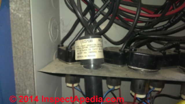
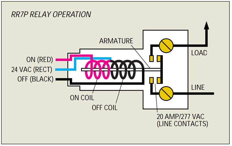
PDF Lighting Controls LIGHTING CONTROLS LIGHTING CONTROLS GE LIGHTING RELAYS MODELS RR-7, RR-9 382 2004 KELE CATALOG • • USA 888-397-5353 • International 901-382-6084 The relay employs a split low-voltage coil to move the line voltage contact armature to the on or off latched position.
Ge Relay 3Arr3 - BuyerPricer.com
Rr7 Relay Wiring Diagram - schematron.org there are two relays which will not work because a mouse ate the Look at the diagram: graphic. Wall Switch Sensors designed to directly control the G.E. RR-7 Relay. The patented power sensor to function properly (see wiring diagram). The other leg of. This makes remote switching of lighting circuits . RR7. Standard 3-wire relay with stripped leads.

32 Ge Rr7 Relay Wiring Diagram - Worksheet Cloud
GE RR7PBP - 20A SPST Low Voltage Relay - Galesburg Electric/Industrial ... GE RR7PBP - 20A SPST Low Voltage Relay Features: GE RR7PBP (replacement for RR7P) Rated 20 amp, 277 volt, 5-pin plug end can be snipped off for use in non-digital panels Suitable for use on circuit capable of delivering not more than 10 kA Sym. Amps, 277 Maximum. SPST (single pole single throw) maintained mechanical relay module, 6" wire leads

Kyle Switch Plates
GE RR9 Lighting Relays with 2-Wire Control Scheme - YouTube About Press Copyright Contact us Creators Advertise Developers Terms Privacy Policy & Safety How YouTube works Test new features Press Copyright Contact us Creators ...
![[FAQ] GE 3-Way Wiring - FAQ - SmartThings Community](https://aws1.discourse-cdn.com/smartthings/original/3X/c/9/c98f8522371b13ab0c0345bbac79c9a20a00e3ce.gif)
[FAQ] GE 3-Way Wiring - FAQ - SmartThings Community
PDF 2R7 & 2R9 Relay Operational Summary - Intelligent Lighting Contorls 2R7 and 2R9 split coil relay's unique con-struction has only one movable part (the contacts). This reliable relay design has a proven failure rate of less than .001 per-cent. It offers both the popular GE RR7 relay footprint and functionality (3 wire control) along with extreme reliability. The following describes the actual inter-
GE RR9 Lighting Relays with 2-Wire Control Scheme - YouTube
GE RR3 Relays | Electrician Talk I am working in a house with GE RR3 relays used in lighting circuits. I expected these circuits to be similar to 3-Wire motor start / stop stations. However, I found that the rocker switch, used with the relay, uses normally open, momentary contacts for both on and off.
42 Ge Rr7 Relay Wiring Diagram - Wiring Diagram Source Online
Fabulous Ge Rr7 Relay Modern House Wiring Diagram 35 Unique Ge Rr7 Relay Wiring Diagram In 2020 Electromagnet Import 5 Way Switch Strat 3 Phase Magnetic Contactor Ge Rr7 Low Voltage Remote Control Relay Switch Rr7pbp Three Way Wire Triton Boat Battery Wiring Double Pole 39 94 Ge Rr7 20a Spst Low Voltage Relay Description 3 Prong Light Switch Motor Wiring Diagram Pdf

Kyle Switch Plates: August 2018
Ge Rr7 Relay / G E Rr7 Relay Ge Rr 7 Low Voltage Remote Control Relay Switch ... Rr7 relay wiring diagram rr7 ge relay wiring diagram of a picture i get ge rr7 wiring diagram schematics data wiring diagrams. Ge rr7 low voltage lighting relay system. The ge rr7 low voltage relay is a direct replacement for older ge brand rr2 rr3 and rr5 mechanical latching relays.
GE RR7P - 20A SPST Low Voltage Relay
GE Low Voltage Switch & Relay Wiring Instruction Guide Description Read this Kyle Switch Plates exclusive instructions for installing newer GE RS2 series low voltage switches in remote control wiring systems using RR7, RR8 or RR9 mechanical relays and RT series transformers. Included for free with the purchase of any GE low voltage lighting component. One copy per purchase

I have a GE Low Voltage Remote Relay RR7 with a blue/black/red wire. I am replacing the ceiling ...
Rr9 Relay Wiring Diagram | Wiring Diagrams Nea rr7 relay wiring diagram. the on coil moves the armature to the on position when a 24 vac control signal is impressed across its leads 2 5 1 rr9 relay wiring diagram 24 wiring diagram images wiring diagrams wiringall comindex of wiringall com. rr9 relay low voltage 20 amp 277 volt wiring forums. 30 11 2017 this is the rr9 relay low voltage 20 ...
0 Response to "38 ge rr7 relay wiring diagram"
Post a Comment