41 fan center wiring diagram
PDF Honeywell Fan Center Wiring Diagram Honeywell Fan Center Wiring Diagram inside Honeywell Fan Limit Switch Wiring Diagram by admin Through the thousand pictures on the net regarding honeywell fan limit switch wiring diagram, we all choices the best collections together with ideal resolution just for you, and this images is usually PDF WHITE-RODGERS Fan & Limit Control - Emerson Electric Replace control cover after wiring and making any adjustments to the settings. WHITE-RODGERS DIVISION EMERSON ELECTRIC CO. 9797 REAVIS RD., ST. LOUIS, MO. 63123-5398 (314) 577-1300, FAX (314) 577-1517 9999 HWY. 48, MARKHAM, ONT. L3P 3J3 (905) 475-4653, FAX (905) 475-4625 OPERATION Wiring
PDF Furnace Fan Center Wiring Diagram - testdub.smartleaf.com Fan Center Wiring Diagram can be taken as capably as picked to act. 2016 CALIFORNIA CODES KITCHEN, BATH & LAUNDRY … that can be used for alarm wiring. Battery-only alarms are allowed for alterations solely on the exterior (re- roofing, decks, new windows) and for work limited to alteration or repair of plumbing, mechanical, or electrical
Fan center wiring diagram
White Rodgers Fan Control Center Wiring Diagram Aug 13, 2021 · Wiring Diagrams August 13, 2021 04:07. White Rodgers Fan Control Center Wiring Diagram – One of the most difficult automotive repair tasks that a mechanic or repair shop can bow to is the wiring, or rewiring of a car’s electrical system. The problem in fact is that every car is different. bearing in mind irritating to remove, replace or ... White Rodgers 90 113 Wiring Diagram - schematron.org WHITE-RODGERS The 25M series gas control is a compact, multifunctional valve, with a direct-acting TYPICAL WIRING DIAGRAM FOR MODEL 25M APPLIANCE VALVE TYPICAL WIRING DIAGRAM FOR MODEL 25M MANIFOLD VALVE Typical Wiring Diagrams. 6 25M GAS CONTROL PRODUCT INFORMATION 30 40 50 60 70 80 90 Pressure Drop ("W.C.) X 2. Ceiling Fan Wiring Diagram: A Complete Tutorial | EdrawMax The best and easy-to-use software for making ceiling fan wiring diagrams is the EdrawMax. EdrawMax is entirely free to use diagram-making software that helps you to make diagrams of any region. The software comes with all the essential tools and features that make your work efficient.
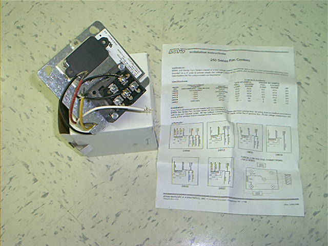
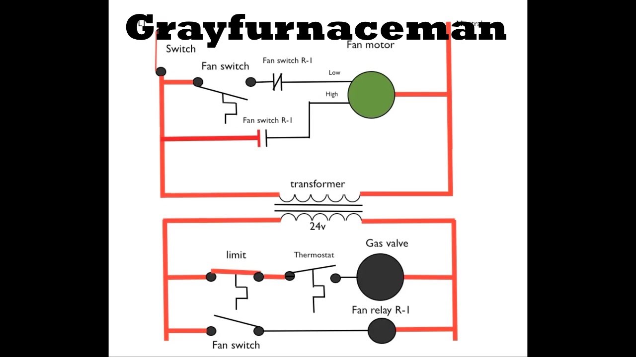
Fan center wiring diagram. 41 honeywell fan center wiring diagram - Wiring Diagram Source Apr 05, 2022 · HONEYWELL L4064T INSTRUCTIONS [PDF] (ca 1970) wiring diagram shown below thanks to reader Haydn Chambers, used an extra set of spade terminals in the center of the control - these were connected to low-voltage terminals that provided a fan-timer heater function such as shown in the illustration that includes a low-voltage (24VAC) gas valve and ... Fan Control Center Wiring Diagram - easywiring Sep 10, 2021 · A wiring diagram is a type of schematic which makes use of abstract photographic signs to show all the interconnections of components in a system. Fan control center wiring diagram. Symbols that stand for the parts in the circuit and lines that. How the fan center works - YouTube This video is about The fan center is used on furnaces to turn on the fan without the heat or if air conditioning. This video is part of the heating and co... PDF Fan Control Centers - Emerson Electric When making line-voltage connections, be sure no connections are made to low- voltage control circuit. Make all line voltage connections following the information recorded previously. Mount the fan control center on the junction box. Connect low voltage wiring to terminal board on fan control center following hookups recorded previously. NOTE
Fan Control Center Wiring - Ask Me Help Desk Run L1, the black wire from the house wiring, to the common of the relay. Connect the high speed lead to the NOC contact of the relay. Connect the NCC contact of the relay to the common of a 3 pole switch. Connect the low and high speed leads to the second and third poles of the 3 pole switch leaving the first as off. Honeywell Fan Center Wiring Diagram inside Honeywell Fan ... Honeywell Fan Center Wiring Diagram inside Honeywell Fan Limit Switch Wiring Diagram by admin Through the thousand pictures on the net regarding honeywell fan limit switch wiring diagram, we all choices the best collections together with ideal resolution just for you, and this images is usually one of graphics collections inside our very best photographs gallery in relation to Honeywell Fan ... Fan Control Center Wiring Diagram - Wiring World Aug 09, 2021 · A wiring diagram is a type of schematic which makes use of abstract photographic signs to show all the interconnections of components in a system. 90 113 Fan Control Center Wiring Diagram wiring diagram is a simplified satisfactory pictorial representation of an electrical circuit. Fan Relay Wiring Diagram - easywiring Spdt relay wiring diagram wiring diagrams click 12 volt relay wiring diagram. How to wire a fan center relay. The first part of the installation is to install the electric fan to your radiator and remove the mechanical fan. 86 gray white wire goes to the ignition switch. 87 red wire connects to the positive wire on the electric fan.
PDF Honeywell Fan Center Wiring Diagram Honeywell Fan Center Wiring Diagram read online for free, however, you need to create an account with Bibliotastic in order to download a book. The site they say will be closed by the end of June 2016, so grab your favorite books as soon as possible. Honeywell Fan Center Wiring Diagram Honeywell Fan Center Wiring Diagram inside Honeywell Fan ... 90-112 THRU 90-130 FAN CONTROL CENTER - Emerson ... Additional terminal Y and W are isolated tie point terminals to connect thermostat wiring to compressor and furnace (if required). NOTE: Record the lead wire ... Adding Fan Control Center - DoItYourself.com Wire relay Com and Relay N.O. (of the fan center) parallel to your fan limit. So your diagram Black goes to relay Com wire and Blue goes to the relay N.O. (Normally open) wire. Wire Transformer black to the hot black wire in your drawn diagram. Wire tranformer white to furnace Neutral. On the low voltage side... Fan center R connects to Nest Rc. Fan Control Center Wiring Diagram Gallery - Wiring Diagram ... Jun 19, 2018 · fan control center wiring diagram – What is a Wiring Diagram? A wiring diagram is a straightforward visual representation from the physical connections and physical layout of your electrical system or circuit. It shows how the electrical wires are interconnected and can also show where fixtures and components might be coupled to the system.
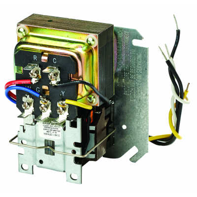
R8285B1038/U
PDF Furnace Fan Center Wiring Diagram Furnace Fan Center Wiring Diagram is available in our book collection an online access to it is set as public so you can download it instantly. Our digital library spans in multiple locations, allowing you to get the most less latency time to download any of our books like this one.

Honeywell FAN Centers R8239A-H AT72H,J Q633A User Guide ...
Zettler 90113 Fan Center Wiring Diagram Abstract: F transistor zc F AB E F ZCSP ZC ZC90 wiring diagram klixon THERMOSTAT freezer SCHEMATIC gb RELAY/TRANSFORMER FAN CENTER ASSEMBLY Zettler Controls. RELAY/TRANSFORMER FAN. CENTER Zettler Controls, Inc. Fan Center controls provide convenient low Each ZC fan 4" square electrical junction box cover. ZC DPDT Relay. DPDT Relay.

Pin by jason norris on Solo Electrico | 4 way light switch, 3 ...
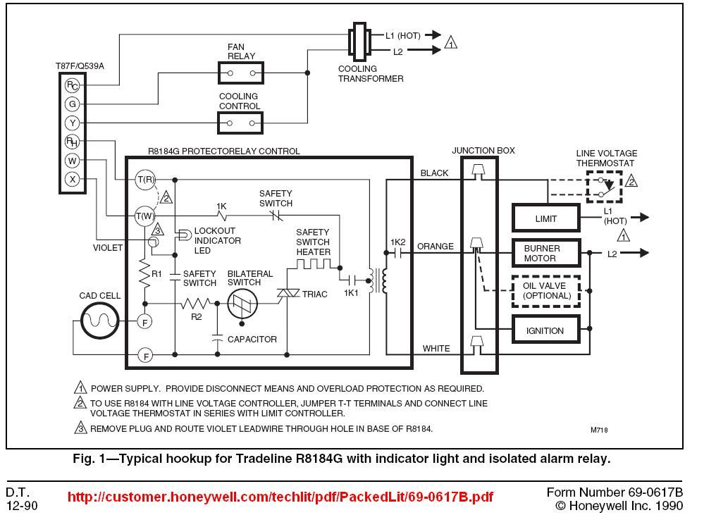
How to Install & Wire the Fan & Limit Controls on Furnaces ... HONEYWELL L4064T INSTRUCTIONS [PDF] (ca 1970) wiring diagram shown below thanks to reader Haydn Chambers, used an extra set of spade terminals in the center of the control - these were connected to low-voltage terminals that provided a fan-timer heater function such as shown in the illustration that includes a low-voltage (24VAC) gas valve and ...

All Wiring Diagrams for Chrysler Pacifica 2006 – Schematy ...
PDF Honeywell Fan Center Wiring Diagram - cms.nationnews.com Honeywell Fan Center Wiring Diagram - thank you for visiting our site. At this time were pleased to announce we have found a very interesting niche to be reviewed, namely honeywell fan center wiring diagram.Lots of people attempting to find details about honeywell fan center wiring diagram Honeywell Fan Control Center Wiring - mitrabagus.com
Electrical Component List 1. White Rodgers #90-113 Fan ...
Honeywell Fan Center Wiring Diagram - bb.bravewords.com Download Ebook Honeywell Fan Center Wiring Diagram First of all, check the wiring of the ceiling fan to make sure that it is wired properly and is receiving the full power Check the remote to make sure that it is working perfectly Now, remove the ceiling fan receiver (after turning off the main power) and check to make sure that the dip ...

23 Complex Wiring Diagram Online For You - bacamajalah ...
White Rodgers Fan Center Relay Wiring Diagram Nov 30, 2017 · 8a05a 201 Emerson White Rodgers Relay Transformer 120vac Enclosed Spdt Amre Supply. Honeywell L4064b Combination Fan And Limit Control How To Set The Temperatures Limits On Furnace Switch. White Rodgers 90 113 Rbm Fan Control Center Hvac Controls. White Rodgers 8a04 1 Catalog Page Manualzz. 90 370 White Rodgers Fan Relay Arnold S Service Co Inc.
Fan center for older furnaces
Air handler wiring diagram. - mottorides.de ECU Wiring Diagrams. + other fans as shown Brown Black Blue M 1~ Green/Y ellow Brown Cap Black CE31 only Single phase AC motor with capacitor Blue or Grey A N SILDES These diagrams mainly apply to EXTERNAL ROTOR MOTORSbut some standard Apr 28, 2019 · Nordyne Wiring Diagram Air Handler- wiring diagram is a simplified normal pictorial ...
Fan Control Center: Wrong wiring or bad part? | DIY Home ...
Fan Control Center Wiring - Ask Me Help Desk The fan control has 2 black wires coming out of the switch in the back that is normally open. And 2 red wires from a switch that is normally closed. Also, a black and a white wire that go to the transformer. The fan limit switch has 3 wires going to it (red,blue and black). Any help repairing this mess would be appreciated. Thanks,
proper fan control center wiring | DIY Home Improvement Forum
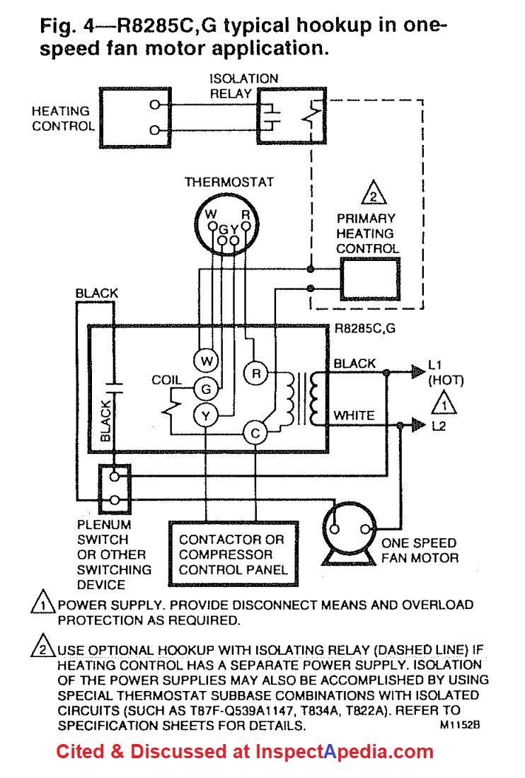
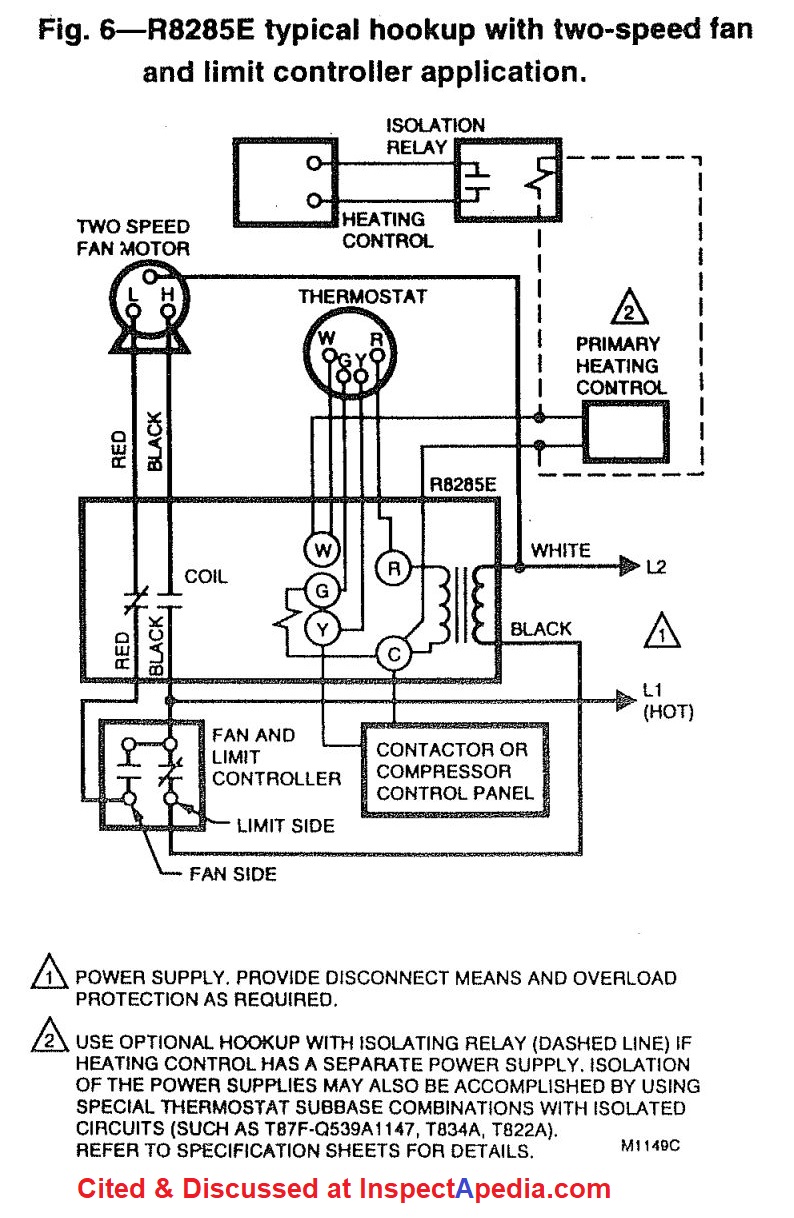
PDF 69-0482 R8285A,B CONTROL CENTERS - Honeywell Refer to Figs. 2 or 3 for typical wiring diagrams. Fig. 1—Schematic for single and multitap transformers. Fig. 2—R8285A typical hookup in two-speed fan motor application. POWER SUPPLY. PROVIDE DISCONNECT MEANS AND OVERLOAD PROTECTION AS REQUIRED. USE OPTIONAL HOOKUP WITH ISOLATING RELAY (DASHED LINE) IF HEATING CONTROL HAS A SEPARATE POWER SUPPLY.
Hooking up Smart Thermostat to a Fan Center Relay
PDF Suggested Electric Fan Wiring Diagrams - DaveBarton.com Suggested Electric Fan Wiring Diagrams PAGE 1 These diagrams show the use of relays, ON/OFF sensors, ON/OFF switches and ON/OFF fan controllers. ... RECOMMENDED WIRE SIZES: 8-10 GA: FAN POWER AND GROUND. 16-18 GA: ALL OTHERS. PAGE 4 OPTIONAL RELAY OVERRIDES TEMP SENSOR AND TURNS ON FANS WHEN A/C IS TURNED ON BATTERY 86 30 87 85 86
Honeywell L4064B Combination Fan and Limit Control: How to ...
White Rodgers 90 113 Wiring Diagram White Rodgers 90 113 Wiring Diagram White Rodgers 90 113 Wiring Diagram Transformer. Contact Ratings. Model. Mars. Primary. Secondary Color coded. 24V. 40 Terminal board SPDT. . isolated tie point terminals to connect thermostat wiring to compressor and furnace (if. Thru Fan Control Center. White-Rodgers. Share.

Ceiling Fan Wiring Diagram #1 | Electrical wiring, Ceiling ...
Honeywell Fan Center Wiring Diagram Bookmark File PDF Honeywell Fan Center Wiring Diagram Air Conditioning and Refrigeration The essential introduction to the principles and applications of feedback systems—now fully revised and expanded This textbook covers the mathematics needed to model, analyze, and design feedback systems.

50 Luxury Air Handler Fan Relay Wiring Diagram | Ac wiring ...
Ceiling Fan Wiring Diagram: A Complete Tutorial | EdrawMax The best and easy-to-use software for making ceiling fan wiring diagrams is the EdrawMax. EdrawMax is entirely free to use diagram-making software that helps you to make diagrams of any region. The software comes with all the essential tools and features that make your work efficient.
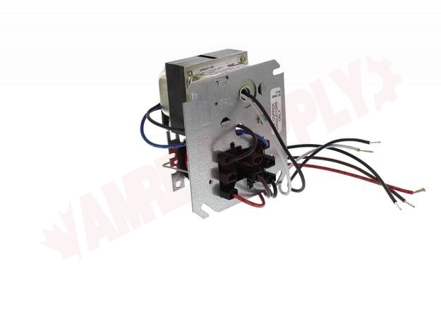
R8285A1048 : Resideo Honeywell Fan Center/Relay Transformer ...
White Rodgers 90 113 Wiring Diagram - schematron.org WHITE-RODGERS The 25M series gas control is a compact, multifunctional valve, with a direct-acting TYPICAL WIRING DIAGRAM FOR MODEL 25M APPLIANCE VALVE TYPICAL WIRING DIAGRAM FOR MODEL 25M MANIFOLD VALVE Typical Wiring Diagrams. 6 25M GAS CONTROL PRODUCT INFORMATION 30 40 50 60 70 80 90 Pressure Drop ("W.C.) X 2.

Electric fan on a 1974 Triumph TR6
White Rodgers Fan Control Center Wiring Diagram Aug 13, 2021 · Wiring Diagrams August 13, 2021 04:07. White Rodgers Fan Control Center Wiring Diagram – One of the most difficult automotive repair tasks that a mechanic or repair shop can bow to is the wiring, or rewiring of a car’s electrical system. The problem in fact is that every car is different. bearing in mind irritating to remove, replace or ...
How to Install & Wire the Fan & Limit Controls on Furnaces ...
How to Install & Wire the Fan & Limit Controls on Furnaces ...
Wiring fan control relay | DIY Home Improvement Forum
Hooking up Smart Thermostat to a Fan Center Relay

Adding Fan Control Center - DoItYourself.com Community Forums
hvac - Force Furnace Blower to Run on Separate Schedule to ...
FIXED - Janitrol Furnace Fan will run on "RUN" but not on ...

Basic Electricity. - ppt video online download
حاصل على ميدالية مدير المدرسة تعيين cooling fan relay wiring ...

Blower not running in A/C mode - DoItYourself.com Community ...

Rear A/C condenser fan relay wiring diagram - Pelican Parts ...

R8239D1007 : Resideo Honeywell Fan Center/Relay Transformer ...

A/C stopped working after a burning smell - DoItYourself.com ...

Fan Limit Control Installation FAQs

All Wiring Diagrams for Hyundai Accent GLS 2006 – Schémata ...

R8285A1048 : Resideo Honeywell Fan Center/Relay Transformer ...
Honeywell L4064B Combination Fan and Limit Control: How to ...
Schematic diagram #7. 2 speed fan switch.

R8285A-G, J, K Control Centers | Manualzz

I'm trying to replace my fan control center (White-Rodgers ...
ElectricalForGas- Fan Centers
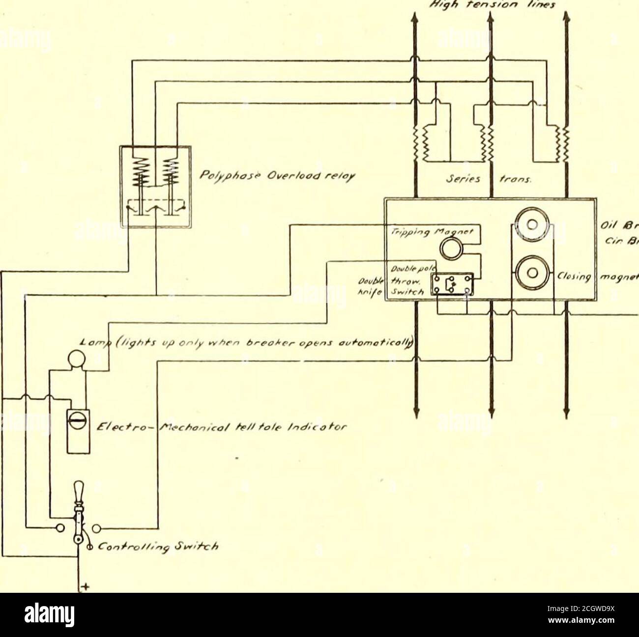
The Street railway journal . FIG. 1. — ELECTRO-PNEUMATIC ...

A/C stopped working after a burning smell - DoItYourself.com ...

WHITE RODGERS 90-113 RBM FAN CONTROL CENTER HVAC Controls HVAC
Ecobee Help...dual thermostat Wiring diagram for powering ...

Honeywell R8285A1048 Fan Center
0 Response to "41 fan center wiring diagram"
Post a Comment